EP0573396A1 - Steckverbindersystem - Google Patents
Steckverbindersystem Download PDFInfo
- Publication number
- EP0573396A1 EP0573396A1 EP93810395A EP93810395A EP0573396A1 EP 0573396 A1 EP0573396 A1 EP 0573396A1 EP 93810395 A EP93810395 A EP 93810395A EP 93810395 A EP93810395 A EP 93810395A EP 0573396 A1 EP0573396 A1 EP 0573396A1
- Authority
- EP
- European Patent Office
- Prior art keywords
- plug
- coding
- socket
- connector system
- grooves
- Prior art date
- Legal status (The legal status is an assumption and is not a legal conclusion. Google has not performed a legal analysis and makes no representation as to the accuracy of the status listed.)
- Granted
Links
- 238000003780 insertion Methods 0.000 claims abstract description 5
- 230000037431 insertion Effects 0.000 claims abstract description 5
- 230000002093 peripheral effect Effects 0.000 claims abstract description 4
- 230000005405 multipole Effects 0.000 claims abstract description 3
- 210000001520 comb Anatomy 0.000 claims description 20
- 230000001419 dependent effect Effects 0.000 description 2
- 238000010586 diagram Methods 0.000 description 2
- 239000000463 material Substances 0.000 description 2
- 229910052751 metal Inorganic materials 0.000 description 2
- 239000002184 metal Substances 0.000 description 2
- 150000002739 metals Chemical class 0.000 description 2
- 239000004033 plastic Substances 0.000 description 2
- 229920003023 plastic Polymers 0.000 description 2
- 238000000926 separation method Methods 0.000 description 2
- 229910000838 Al alloy Inorganic materials 0.000 description 1
- 239000004952 Polyamide Substances 0.000 description 1
- 230000015572 biosynthetic process Effects 0.000 description 1
- 230000000694 effects Effects 0.000 description 1
- 238000010292 electrical insulation Methods 0.000 description 1
- 238000002347 injection Methods 0.000 description 1
- 239000007924 injection Substances 0.000 description 1
- 238000009413 insulation Methods 0.000 description 1
- 239000012212 insulator Substances 0.000 description 1
- 238000004519 manufacturing process Methods 0.000 description 1
- 229920002647 polyamide Polymers 0.000 description 1
- 229920000728 polyester Polymers 0.000 description 1
- 229920001169 thermoplastic Polymers 0.000 description 1
- 239000004416 thermosoftening plastic Substances 0.000 description 1
Images



Classifications
-
- H—ELECTRICITY
- H01—ELECTRIC ELEMENTS
- H01R—ELECTRICALLY-CONDUCTIVE CONNECTIONS; STRUCTURAL ASSOCIATIONS OF A PLURALITY OF MUTUALLY-INSULATED ELECTRICAL CONNECTING ELEMENTS; COUPLING DEVICES; CURRENT COLLECTORS
- H01R13/00—Details of coupling devices of the kinds covered by groups H01R12/70 or H01R24/00 - H01R33/00
- H01R13/64—Means for preventing incorrect coupling
- H01R13/645—Means for preventing incorrect coupling by exchangeable elements on case or base
- H01R13/6456—Means for preventing incorrect coupling by exchangeable elements on case or base comprising keying elements at different positions along the periphery of the connector
Definitions
- Connector system for multipole electrical plugs with a coding to avoid undesired plugging into a suitable socket which plug connector system comprises standardized, intermeshable comb / groove pairs, whereby 0.1 ... or n combs of the plug are removed according to the rules of combinatorics , and a wedge is clamped in 0.1 ... or n grooves of the socket, and to use the connector system.
- U 8325310 shows a coding device for multiple plug connections with a unit that can be changed as required.
- the holding device with insertable coding elements is, viewed in the direction of insertion, arranged outside the contact area. Recesses of the coding element holding device that are not occupied by coding elements are receiving spaces for the protruding free ends of the inserted coding elements of the opposite coding element holding device.
- the coding element holding device is formed in one piece on the plug holder as a cantilever arm and directly adjacent to the plug strip.
- the end face of the connector holder is not protruding laterally and is formed in an extension thereof in the plug-in direction (S).
- the contact and coding area are on one level and are closely interwoven, only front-mount connectors are possible.
- the inventor has set himself the task of improving a connector system of the type mentioned at the outset with a coding device to avoid undesired connections of plugs to sockets without increasing the number of uniformly standardized coding elements.
- the invention further relates to a use of the connector system.
- the object is achieved according to the invention in that the coding system and the contact system of socket and plug are spatially separated in the plugging direction. Further and special embodiments of the invention are the subject of dependent claims.
- the coding and contact systems are independent of one another, the contact system can also be connected to the coding system in an exchangeable manner.
- Round connector systems with a nose / groove pair used for positioning the connector have nothing to do with the present invention because they are not interchangeable Have coding elements and - this is of particular importance - the unchangeable nose / groove pair is in the same area as the contact system.
- the coding system is expediently designed as a pair of comb / groove pairs which are known per se and can be plugged into one another.
- 2 to 5, in particular 3 or 4 pairs of ridges / grooves are preferably formed, this number being designated by n.
- n the number of ridges / grooves are preferably formed, this number being designated by n.
- 0, 1, 2, .... or n interchangeable wedges can be clamped in the n grooves depending on the position. Is e.g. A replaceable wedge is clamped in one of the n grooves of a socket insert, the plug can only be inserted and the electrical contact made if the plug has no comb in the same position. If there are several grooves with a key inserted, the connector must not have a comb at any corresponding position.
- the number of contacts in a connector system can vary from one to several hundred, the arrangements noted here range from four to 16 poles. In the lower number of contacts in the latter area, three pairs of ridges / grooves are advantageous for the coding system in the upper number of contacts, although there is of course no restriction in this regard.
- the connector housing and the coding frame for a socket which in the context of the invention is also a connector attachment, are preferably essentially rectangular or square, whereby crests and grooves can be distributed over the entire circumference or arranged on one long side.
- a coding frame can also be round or oval.
- a wedge is inserted into at least one groove, this means that at least one comb must be missing on each connector housing at the corresponding positions, otherwise the connector cannot be inserted. If all possible combs are designed for a plug housing, this can only be inserted into the socket insert without inserting a wedge. If all combs are missing in a connector housing, the connector can be inserted into all connector fastenings.
- Geometrically different in groups are, for example, four cross / groove pairs at positions 1 and 2 rectangular, at positions 3 and 4 semicircular cross-sections. In contrast, with individually geometrically different cross sections, positions 1 and 3 are rectangular, positions 2 and 4 are semicircular. The same applies to the size of the cross sections.
- the combs are made in one piece with the connector housing and the webs forming the grooves are made in one piece with the connector attachment in the socket, but they can also be welded, glued or latched to them.
- Combs and / or webs can also be inserted or screwed down, but this is usually more complex.
- the spatial separation according to the invention of the coding and contact system in the plug-in direction not only increases the variety, but the mechanical guidance of the plug outside the socket is also particularly advantageous due to the coding frame which forms a housing extension and which also offers protection against mechanical damage, be it from the side Pull on the cable or by blows.
- the connector system can be used for all electrical connections from plugs to sockets in which undesired electrical contacts must be avoided.
- the invention is the use for electrical connections on communication main and peripheral devices particularly advantageous, for example ISDN, telephone, terminal and modem, as well as PC, host or data network systems.
- the connector system according to the invention comprises a safe, flexible coding system which can be changed at any time with the coding and contact system being spatially separated in the plug direction, which not only enables uniformly standardized plugs and socket inserts, but also allows the same coding system for different plugs. This can improve economy and simplify application.
- the plug connector system S shown in FIG. 1 essentially comprises a coding frame 10 for a socket, which is part of the plug and socket fastening 11 (FIG. 2), a plug housing 12 and a socket insert 14.
- the upwardly projecting coding frame 10 is formed in one piece with a circumferential, square cover frame 16 which is chamfered in the peripheral area.
- the cover frame 16 can be a distribution plate, also called a panel, with several molded or attached coding frames 10.
- the coding frame 10 On one long side, the coding frame 10 has inwardly projecting webs 18, which form three undercut grooves 20. Two of these undercut grooves, in positions I and II, are filled with an inserted wedge 22. The grooves narrow slightly in the direction of view, whereby a clamping effect is achieved which effectively prevents the wedges 22 from falling out.
- the connector housing 12 has a comb 24 projecting into a groove 20 in position III. In positions I and II only a short stump of the combs can be seen, these are separated. If the connector housing 12 also had a comb 24 in positions I and / or II, the connector could not be inserted.
- the coding system 26 consisting of the grooves 20, the wedges 22 and the combs 24 with the positions I, II and III is designed as a unit that can be changed at any time outside the contact area of the standard connector according to the FCC, which is dealt with here. The change is made by inserting or removing wedges 22 and / or combs 24 in a position-specific manner. Details are shown in FIG. 8.
- the perspective view of the socket attachment 11 according to FIG. 2 shows the design of the coding system 26 (without the combs 24 of the connector housing 12 according to FIG. 1) more clearly.
- the wedge 22 is adapted to the shape of the undercut grooves 20. It can be inserted in the direction of arrow 28, which is also the direction of insertion R, and removed in the opposite direction. To facilitate the Two cutouts 30 are provided along the center.
- a collar 32 is formed with a guide tab 34 for the socket (not shown).
- This collar 32 also has two outer locking lugs 36 for the frame fastening and four inner locking lugs 38 for the socket insert 14 (FIG. 1).
- Fig. 3 shows a connector system S in a perspective view with a connector attachment 11 and a plug 40 inserted in the plug-in direction R.
- An electrical cable 44 is guided via a flexible cable connection 42 into the plug housing 12, from which a replaceable standard plug 46 protrudes, which the electrical Contacts 48, sockets or pins, in the case shown so-called sliding contacts, holds.
- the plug 40 according to FIG. 3 can only be inserted in a socket insert 14 (not shown) (FIG. 1) if all the grooves 20 of the coding frame 10 are free, that is to say all the wedges 22 are removed. If a wedge 22 is inserted into one or more grooves 20, the corresponding comb 24 must be removed from the connector housing 12, otherwise the connector 40 cannot be inserted.
- a locking bracket 50 is shown, which secures the plug 40 inserted.
- the combs 24 are formed in one piece with the plug housing 12, but they can also be glued on, welded on or inserted into a correspondingly designed groove. This also applies to the attachment with the webs 18 according to FIG. 2.
- the connector attachment 10 and the connector housing 12 can be made of any material that is injection molded or cast and that can be machined. However, dimensionally stable plastics are preferred because of their insulation properties.
- FIG. 5 shows a combination diagram with a groove N and a comb K.
- N 1.1 the groove is empty, at N 1.2 a wedge is inserted, which is shown with a diagonal line.
- the K 1.1 comb fits into the assigned empty groove.
- the ridge of the K 1.2 is removed, which is shown with an X.
- K 1.2 also corresponds to an uncoded connector.
- N 1.1 and K 1.1 as well as N 1.2 and K 1.2 always match in pairs.
- the removed comb K 1.2 can also be used for the groove N 1.1, but K 1.1 not for N 1.2.
- N 2.1 without inserted wedge is free for all comb variants K 2.1 to K 2.4, N 2.2 and N 2.3 can be used in addition to the assigned variant of K 2.4, which also corresponds to an uncoded plug.
- the combinations can also be assessed based on the combs.
- FIG. 7 shows the possible combinations of three pairs of ridges / grooves, positions I, II and III according to FIGS. 1 and 2 being shown.
- 1 corresponds to N 3.5.
- the arrangement K 3.8 can also be inserted into this groove arrangement, which arrangement corresponds to a plug without a coding system and works with every groove combination.
- the comb combinations K 3.2, K 3.5, K 3.6 and K 3.8 can be inserted into the slot combination N 3.2.
Landscapes
- Connector Housings Or Holding Contact Members (AREA)
- Details Of Connecting Devices For Male And Female Coupling (AREA)
- Paper (AREA)
- Quick-Acting Or Multi-Walled Pipe Joints (AREA)
Abstract
Description
- Steckverbindersystem für mehrpolige elektrische Stecker mit einer Codierung zum Vermeiden eines unerwünschten Steckens in eine dazu passende Steckdose, welches Steckverbindersystem einheitlich standardisierte, ineinandersteckbare Kamm-/ Nutenpaare umfasst, wobei nach den Regeln der Kombinatorik 0,1... oder n Kämme des Steckers entfernt sind, und in 0,1... oder n Nuten der Dose ein Keil festgeklemmt ist, und auf eine Verwendung des Steckverbindersystems.
- Es sind verschiedenste Fabrikate von Steckverbindern auf dem Markt, beispielsweise mit 4, 6, 8, 10, 12, 14 oder mehr Polen, wie die Kontakte auch genannt werden. Unerlaubte, unrichtige, falsche, nicht systemkonforme, artfremde oder systemschädliche Anschlüsse werden vermieden, indem die Steckverbinder bestimmte geometrische Formen und/oder äussere Abmessungen haben. Für jede Kontaktanzahl muss also eine bestimmte geometrische Form geschaffen werden, was in bezug auf Herstellung, Lagerhaltung und Verarbeitung kompliziert und aufwendig ist. Immerhin ist jedoch gewährleistet, dass sowohl Buchsen- als auch Stiftkontakte exakt aufeinander geführt werden.
- Bei runden Steckverbindern wird durch ineinandergeführte Nase und Nut gewährleistet, dass die Kontakte exakt aufeinander liegen. Unerwünschte Anschlüsse runder Steckverbinder können durch unterschiedliche Durchmesserausbildung oder Isolierkörperverdrehung verhindert werden. Für diesbezügliche bekannte Bauteile wird beispielsweise auf die Firmenschrift "Runde Industrie-Steckverbinder, CA-COM und CA-COM-B" der Firma ITT-Cannon (C1/680) verwiesen.
- Die DE,U 8325310 zeigt eine Codiervorrichtung für Mehrfach-Steckverbindungen mit einer nach Bedarf veränderbaren Einheit. Die Haltevorrichtung mit einsetzbaren Codierelementen ist, in Steckrichtung betrachtet, ausserhalb des Kontaktbereichs angeordnet. Nicht von Codierelementen besetzte Ausnehmungen der Codierelement-Haltevorrichtung sind Aufnahmeräume für die überstehenden freien Enden der eingesetzten Codierelemente der gegenüberliegenden Codierelement-Halte-vorrichtung. Die Codierelement-Haltevorrichtung ist einstückig an der Stecker-Halterung als Kragarm ausgebildet und unmittelbar benachbart zur Steckerleiste. Die Stirnfläche der Stecker-Halterung ist seitlich nicht überstehend und in Verlängerung derselben in Steckrichtung (S) ausgebildet. Kontakt- und Codierbereich liegen auf einer Ebene und sind eng miteinander verflochten, es sind nur von vorne montierbare Stecker möglich.
- Der Erfinder hat sich die Aufgabe gestellt, ein Steckverbindersystem der eingangs genannten Art mit einer Codiervorrichtung zur Vermeidung unerwünschter Anschlüsse von Steckern an Dosen ohne Vermehrung der Anzahl einheitlich standardisierter Codierelemente zu verbessern. Weiter betrifft die Erfindung eine Verwendung des Steckverbindersystems.
- In bezug auf die Vorrichtung wird die Aufgabe erfindungsgemäss dadurch gelöst, dass das Codiersystem und das Kontaktsystem von Dose und Stecker in Steckrichtung räumlich getrennt sind. Weiterbildende und spezielle Ausführungsformen der Erfindung sind Gegenstand von abhängigen Patentansprüchen.
- Durch die räumliche Trennung sind Codier- und Kontaktsystem unabhängig voneinander, das Kontaktsystem kann auch auswechselbar mit dem Codiersystem verbunden sein.
- Runde Steckverbindersysteme mit einem der Positionierung des Steckers dienenden, Nase-/Nutpaar haben mit der vorliegenden Erfindung nichts zu tun, weil sie keine auswechselbaren Codierelemente haben und - dies ist von besonderer Bedeutung - das unveränderbare Nase-/Nutpaar im gleichen Bereich wie das Kontaktsystem liegt.
- Zweckmässig ist das Codiersystem als an sich bekannte, ineinandersteckbare Kamm-/Nutenpaare ausgebildet. In der Praxis werden bevorzugt 2 bis 5, insbesondere 3 oder 4 Kamm-/Nutenpaare ausgebildet, wobei diese Anzahl mit n bezeichnet wird. Nach den Regeln der Kombinatorik können 0, 1, 2, .... oder n auswechselbare Keile positionsspezifisch in den n Nuten festgeklemmt werden. Ist z.B. in einer der n Nuten eines Steckdoseneinsatzes ein auswechselbarer Keil eingeklemmt, kann der Stecker nur eingeführt und der elektrische Kontakt hergestellt werden, wenn der Stecker an derselben Position keinen Kamm aufweist. Bei mehreren Nuten mit eingesetztem Keil, darf der Stecker an keiner entsprechenden Position einen Kamm aufweisen.
- Bei n Nuten kann ein Keil in n Positionen festgeklemmt werden, zwei Keile an n.(n-1)/2 Positionen, n Keile in einer Position. Damit lassen sich bei entsprechender Kombination n.(n-1)+1 Codiermöglichkeiten erreichen, z.B. bei drei Nuten 3.2+1=7.
- Es ist offensichtlich, dass mit der Erhöhung der Kamm-/Nutenpaare eine grössere Variationsmöglichkeit für das Codieren besteht, andrerseits wird jedoch das ganze Steckverbindersystem komplizierter und - insbesondere bei kleinen Steckern - kaum mehr problemlos handhabbar.
- Bei einem einheitlich standardisiert ausgebildeten Steckverbindersystem wird lediglich das Codiersystem verändert und ein unerwünschter Anschluss von Steckern an Dosen wird vermieden. Erfindungsgemäss kann dagegen bei verschiedenen Steckern, auch bei runden, derselbe Codierrahmen verwendet werden.
- Obwohl die Anzahl von Kontakten eines Steckverbindersystems von eins bis mehrere hundert variieren kann, liegen die hier beachteten Anordnungen bei vier bis 16 Polen. In den unteren Kontaktzahlen des letzteren Bereichs sind drei, in den oberen Kontaktzahlen vier Kamm-/Nutenpaare für das Codiersystem vorteilhaft, obwohl diesbezüglich selbstverständlich keine Einschränkung besteht.
- Das Steckergehäuse und der Codierrahmen für eine Dose, welcher im Rahmen der Erfindung auch Steckerbefestigung ist, sind vorzugsweise im wesentlichen rechteckig bzw. quadratisch ausgebildet, wobei Kämme und Nuten über den ganzen Umfang verteilt oder an einer Längsseite angeordnet sein können. Selbstverständlich kann ein Codierrahmen auch rund oder oval ausgebildet sein.
- Wird in wenigstens eine Nut ein Keil eingelegt, bedeutet dies, dass an jedem Steckergehäuse an den entsprechenden Positionen wenigstens ein Kamm fehlen muss, sonst kann der Stecker nicht eingesteckt werden. Sind bei einem Steckergehäuse alle möglichen Kämme ausgebildet, kann dieser nur ohne Einlegen eines Keils in den Steckdoseneinsatz eingeführt werden. Fehlen bei einem Steckergehäuse alle Kämme, so kann der Stecker in alle Steckerbefestigungen eingeführt werden.
- Obwohl in der Regel alle Querschnitte der Kamm-/Nutenpaare geometrisch gleich ausgebildet sind, bevorzugt im wesentlichen rechtwinklig, quadratisch, halbkreis-, trapez- oder dreieckförmig, liegt es im Rahmen der vorliegenden Erfindung, diese Querschnitte einzeln oder gruppenweise
- geometrisch unterschiedlich und/oder
- verschieden gross auszugestalten.
- Damit kann die Anzahl von Variationen auch bei einer niedrigen Anzahl von Kamm-/Nutenpaaren praktisch unbegrenzt erhöht werden, das System wird jedoch komplizierter und teurer. Gruppenweise geometrisch unterschiedlich sind beispielsweise bei vier Kamm-/Nutenpaaren an den Positionen 1 und 2 rechteckige, an den Positionen 3 und 4 halbkreisförmige Querschitte. Bei einzel geometrisch unterschiedlichen Querschnitten sind dagegen beispielsweise die Positionen 1 und 3 rechteckig, die Positionen 2 und 4 halbkreisförmig. Bezüglich der Grösse der Querschnitte gilt entsprechendes.
- Nach einer in der Praxis bevorzugten Ausführungsform sind die Kämme einstückig mit dem Steckergehäuse und die die Nuten bildenden Stege einstückig mit der Steckerbefestigung in der Dose ausgebildet, sie können jedoch auch mit diesen verschweisst, verklebt oder verrastet sein. Für eine allfällige Ausbildung der Kämme an der Steckerbefestigung in der Dose und der Stege am Steckergehäuse gilt entsprechendes. Kämme und/oder Stege können auch gesteckt oder verschraubt sein, was jedoch meist aufwendiger ist.
- Für das erfindungsgemässe Steckverbindersystem bieten sich alle üblichen Materialien an, insbesondere spritzbare, formfeste Kunststoffe, wie Polyamide oder thermoplastische Polyester, jedoch auch Metalle, wie Aluminiumlegierungen. Bei Metallen ist in bekannter Weise auf die elektrische Isolation zu achten.
- Die erfindungsgemässe räumliche Trennung von Codier- und Kontaktsystem in Steckrichtung erhöht nicht nur die Vielfalt, von besonderem Vorteil ist auch die mechanische Führung des Steckers ausserhalb der Dose durch den eine Gehäuseverlängerung bildenden Codierrahmen, welcher auch Schutz gegen eine mechanische Beschädigung bietet, sei es durch seitlichen Zug am Kabel oder durch Schläge.
- Das Steckverbindersystem kann für alle elektrischen Anschlüsse von Steckern an Dosen verwendet werden, bei welcher unerwünschte elektrische Kontakte vermieden werden müssen. Erfindungsgemäss ist die Verwendung für elektrische Anschlüsse an Kommunikationshaupt- und Peripheriegeräten besonders vorteilhaft, beispielsweise ISDN, Telefon, Terminal und Modem, sowie PC, Host oder Datennetzwerksysteme.
- Das erfindungsgemässe Steckverbindersystem umfasst ein sicheres, flexibles Codiersystem, welches bei in Steckrichtung räumlich getrenntem Codier- und Kontaktsystem jederzeit veränderbar ist, was nicht nur einheitlich standardisierte Stecker und Steckdoseneinsätze ermöglicht, sondern auch für verschiedene Stecker dasselbe Codiersystem erlaubt. Damit kann die Wirtschaftlichkeit verbessert und die Anwendung vereinfacht werden.
- Die Erfindung wird anhand von in der Zeichnung dargestellten Ausführungsbeispielen, welche auch Gegenstand von abhängigen Ansprüchen sind, näher erläutert. Es zeigen schematisch:
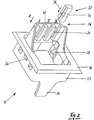
- Fig. 1 eine aufgeschnittene Ansicht eines Steckverbindersystems,
- Fig. 2 eine perspektivische Ansicht eines Codierrahmens für eine Dose, mit Codierung,
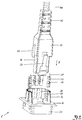
- Fig. 3 eine perspektivische Vorderansicht eines Steckverbindersystems,
- Fig. 4 eine perspektivische Rückansicht des Steckverbindersystems gemäss Fig. 3,
- Fig. 5 ein Kombinationsschema mit einer Nut und einem Kamm,
- Fig. 6 ein Kombinationsschema mit zwei Nuten und zwei Kämmen, und
- Fig. 7 ein Kombinationsschema mit drei Nuten und drei Kämmen.
- Das in Fig. 1 dargestellte Steckverbindersystem S umfasst im wesentlichen einen Codierrahmen 10 für eine Dose, der Bestandteil der Stecker- und Steckdosenbefestigung 11 (Fig. 2) ist, ein Steckergehäuse 12 und einen Steckdoseneinsatz 14.
- Der nach oben abkragende Codierrahmen 10 ist einstückig mit einem umlaufenden, quadratischen Abdeckrahmen 16 ausgebildet, welcher im peripheren Bereich angeschrägt ist. Der Abdeckrahmen 16 kann sinngemäss eine Verteilerplatte, auch Panel genannt, sein, mit mehreren angeformten oder befestigten Codierrahmen 10. An einer Längsseite weist der Codierrahmen 10 nach innen abkragende Stege 18 auf, welche drei hinterschnittene Nuten 20 bilden. Zwei dieser hinterschnittenen Nuten, in den Positionen I und II, sind mit einem eingestossenen Keil 22 ausgefüllt. In Blickrichtung verengen sich die Nuten leicht, wodurch ein Klemmeffekt erzielt wird, welcher das Herausfallen der Keile 22 wirksam verhindert.
- Das Steckergehäuse 12 weist einen in Position III in eine Nut 20 hineinragenden Kamm 24 auf. In den Positionen I und II ist nur noch ein kurzer Stumpf der Kämme zu erkennen, diese sind abgetrennt. Würde das Steckergehäuse 12 in den Positionen I und/oder II auch einen Kamm 24 aufweisen, könnte der Stecker nicht eingeschoben werden.
- Das aus den Nuten 20, den Keilen 22 und den Kämmen 24 bestehende Codiersystem 26 mit den Positionen I, II und III ist als eine auf einfache, jederzeit veränderbare Einheit ausserhalb des Kontaktbereichs des hier behandelten Standardsteckers nach FCC ausgebildet. Die Veränderung erfolgt durch positionsspezifisches Einschieben bzw. Entfernen von Keilen 22 und/oder Kämmen 24. Details sind in Fig. 8 dargestellt.
- In der perspektivischen Darstellung der Steckdosenbefestigung 11 gemäss Fig. 2 ist die Ausbildung des Codiersystems 26 (ohne die Kämme 24 des Steckergehäuses 12 gemäss Fig. 1) besser ersichtlich.
- Der Keil 22 ist der Form der hinterschnittenen Nuten 20 angepasst. Er kann in Richtung des Pfeils 28, welche auch die Steckrichtung R ist, eingeschoben und in der entgegengesetzten Richtung wieder entfernt werden. Zur Erleichterung der Entfernung sind längsmittig zwei Aussparungen 30 angebracht.
- Auf der mit Bezug auf den Abdeckrahmen 16 dem Codiersystem 26 entgegengesetzten Seite des Codierrahmens 10, im Kontaktbereich, ist ein Kragen 32 mit einer Führungslasche 34 für die nicht dargestellte Steckdose angeformt. Dieser Kragen 32 weist weiter zwei äussere Rastnasen 36 für die Rahmenbefestigung und vier innere Rastnasen 38 für den Steckdoseneinsatz 14 (Fig. 1) auf.
- Fig. 3 zeigt ein Steckverbindersystem S in perspektivischer Darstellung mit einer Steckerbefestigung 11 und einem in Steckrichtung R eingeführten Stecker 40. Ein elektrisches Kabel 44 wird über einen flexiblen Kabelanschluss 42 in das Steckergehäuse 12 geführt, aus welchem ein auswechselbarer Standardstecker 46 herausragt, welcher die elektrischen Kontakte 48, Buchsen oder Stifte, im dargestellten Fall sogenannte Gleitkontakte, haltert.
- Am Steckergehäuse 12 sind fünf längslaufende Kämme 24 angeordnet, welche mit den Nuten 20 und Keilen 22 das Codiersystem 26 (Fig. 1) bilden.
- Der Stecker 40 gemäss Fig. 3 kann in einem nicht gezeigten Steckdoseneinsatz 14 (Fig. 1) nur eingeführt werden, wenn alle Nuten 20 des Codierrahmens 10 frei, also alle Keile 22 entfernt sind. Wird in eine oder in mehrere Nuten 20 ein Keil 22 eingeführt, muss der entsprechende Kamm 24 vom Steckergehäuse 12 entfernt sein, sonst kann der Stecker 40 nicht eingeführt werden.
- In der Rückansicht gemäss Fig. 4 ist ein Verriegelungsbügel 50 dargestellt, welcher den eingesteckten Stecker 40 sichert.
- Aus Fig. 3 sind die in Steckrichtung R räumlich getrennten Codier- und Kontaktbereiche besonders gut ersichtlich:
- Am Stecker 40 wird der Codierbereich durch die Kämme 24 gebildet, der Kontaktbereich durch die elektrischen Kontakte 48.
- Nach dem vollständigen Einführen des Steckers liegen nicht entfernte Kämme 24 in nicht mit einem Keil 22 gefüllten Nuten 20 und bilden das Codiersystem 26, welches oberhalb des Abdeckrahmens 16 angeordnet ist. Die Kontakte 48 sind in den hinter dem Kragen 32 angeordneten, nicht sichtbaren Steckdoseneinsatz eingesteckt und bilden das unterhalb des Abdeckrahmens 16 liegende Kontaktsystem 16.
- Weiter ist aus Fig. 3 der erweiterte mechanische Schutz der Kontakte 48, des Standardsteckers 46, des Steckergehäuses 12 und insbesondere des Kabels 44 gut ersichtlich.
- Die Kämme 24 sind mit dem Steckergehäuse 12 einstückig ausgebildet, sie können jedoch auch aufgeklebt, aufgeschweisst oder in eine entsprechend ausgebildete Nut eingeschoben sein. Dies gilt auch für den Aufsatz mit den Stegen 18 gemäss Fig. 2.
- Die Steckerbefestigung 10 und das Steckergehäuse 12 können aus jedem in Formen gespritzten oder gegossenen sowie mechanisch bearbeitbaren Material bestehen. Wegen des Isolationsvermögens sind jedoch formfeste Kunststoffe bevorzugt.
- In Fig. 5 ist ein Kombinationsschema mit einer Nut N und einem Kamm K dargestellt. Bei N 1.1 ist die Nut leer, bei N 1.2 ist ein Keil eingeschoben, was mit einem diagonalen Strich dargestellt ist. Der Kamm K 1.1 passt in die zugeordnete leere Nut. Beim K 1.2 ist der Kamm entfernt, was mit einem X dargestellt ist. K 1.2 entspricht auch einem nicht codierten Stecker.
- N 1.1 und K 1.1 sowie N 1.2 und K 1.2 passen immer paarweise zusammen. Der entfernte Kamm K 1.2 kann auch für die Nut N 1.1 verwendet werden, K 1.1 jedoch nicht für N 1.2.
- Mit einem einzigen Kamm-/Nutenpaar sind die Codiermöglichkeiten sehr gering, dieses Steckverbindersystem ist in der Praxis nur beschränkt verwendbar.
- In den Fig. 6 und 7 werden die gleichen Symbole wie in Fig. 5 verwendet die auf der gleichen Zeile dargestellten Nuten und Kämme sind immer als Kamm-/Nutenpaar verwendbar.
- In Fig. 6 sind die Kombinationsmöglichkeiten von zwei Kamm-/Nutenpaaren dargestellt. N 2.1 ohne eingesetzten Keil ist für alle Kammvarianten K 2.1 bis K 2.4 frei, N 2.2 und N 2.3 können neben der zugeordneten Variante noch von K 2.4, welche auch einem nicht codierten Stecker entspricht, benutzt werden.
- Hier und im übrigen können die Kombinationen auch ausgehend von den Kämmen beurteilt werden.
- In Fig. 7 sind die Kombinationsmöglichkeiten von drei Kamm-/ Nutenpaaren aufgezeigt, wobei die Positionen I, II und III gemäss Fig. 1 und 2 eingezeichnet sind. Fig. 1 entspricht N 3.5. In diese Nutenanordnung kann neben der Kammanordnung K 3.5 noch die Anordnung K 3.8 gesteckt werden, welche einem Stecker ohne Codiersystem entspricht und bei jeder Nutenkombination geht.
- Für die Nutenkombination N 3.1 ohne Keil können alle Kammkombinationen K 3.1 bis K 3.8 gesteckt werden. Die Kammkombination K 3.1 ohne entfernten Kamm dagegen kann nur in die Nutenkombination N 3.1 gesteckt werden.
- In die Nutenkombination N 3.2 können die Kammkombinationen K 3.2, K 3.5, K 3.6 und K 3.8 gesteckt werden.
- Die übrigen Kombinationen der Kamm-/Nutenpaare können entsprechend aus Fig. 7 abgeleitet werden.
- Bei vier und mehr Kamm-/Nutenpaaren ergibt sich gegenüber Fig. 7 grundsätzlich nichts neues. Es können entsprechende Darstellungen aufgezeichnet und die Anzahl Codiermöglichkeiten nach der Formel n.(n-1)+1 rechnerisch abgeleitet werden.
Claims (10)
- Steckverbindersystem (S) für mehrpolige elektrische Stecker (40) mit einer Codierung zum Vermeiden eines unerwünschten Steckens in eine dazu passende Steckdose, welches Steckverbindersystem einheitlich standardisierte, ineinandersteckbare Kamm-/ Nutenpaare (24, 20) umfasst, wobei nach den Regeln der Kombinatorik 0,1... oder n Kämme (24) des Steckers (40) entfernt sind, und in 0,1... oder n Nuten (20) der Dose ein Keil (22) festgeklemmt ist,
dadurch gekennzeichnet, dass
das Codiersystem (26) und das Kontaktsystem (48) von Dose und Stecker (40) in Steckrichtung (R) räumlich getrennt sind. - Steckverbindersystem (S) nach Anspruch 1, dadurch gekennzeichnet, dass das Kontaktsystem (48) auswechselbar mit dem Codiersystem (26) verbunden ist.
- Steckverbindersystem (S) nach Anspruch 1 oder 2, dadurch gekennzeichnet, dass an einem Abdeckrahmen (16) einer Dose ein Codierrahmen (10) oder an einem Panel mit mehreren Dosen eine entsprechende Anzahl Codierrahmen (10) angeformt oder befestigt ist, wobei die Codierrahmen (10) von der dem Kontaktbereich gegenüberliegenden Seite rechtwinklig abkragen.
- Steckverbindersystem (S) nach einem der Ansprüche 1 bis 3, dadurch gekennzeichnet, dass bei einem Kabel (44) mit 4 bis 8 Polen drei Kamm-/Nutenpaare (24,20), bei einem Kabel mit 10 bis 16 Polen vier Kamm-/Nutenpaare angeordnet sind.
- Steckverbindersystem (S) nach einem der Ansprüche 1 bis 4, dadurch gekennzeichnet, dass an einer Längsseite eines rechteckig oder quadratisch ausgebildeten Steckergehäuses (12) wenigstens ein längslaufender Kamm (24) an der entsprechenden Längsseite eines Codierrahmens (10) für eine Dose die gleiche Zahl passender Nuten (20) ausgebildet sind.
- Steckverbindersystem (S) nach einem der Ansprüche 1 bis 5, dadurch gekennzeichnet, dass die Nuten (20) hinterschnitten sind und sich in der Einschieberichtung der Keile (22) vorzugsweise verjüngen.
- Steckverbindersystem (S) nach einem der Ansprüche 1 bis 6, dadurch gekennzeichnet, dass alle Querschnitte der Kamm-/Nutenpaare (24, 20) geometrisch gleich ausgebildet sind, bevorzugt im wesentlichen rechteckig, quadratisch, halbkreis-, trapez- oder dreieckförmig.
- Steckverbindersystem (S) nach einem der Ansprüche 1 bis 7, dadurch gekennzeichnet, dass in der Dose eine Stecker- und Steckdosenbefestigung (11) angeordnet ist, welche auf der Steckerseite den Codierrahmen (10) mit Nuten (20) des Codiersystems (26) und auf der Dosenseite, getrennt durch einen Abdeckrahmen (16), im Kontaktbereich einen Kragen (32) für den Steckdoseneinsatz (14), umfasst.
- Steckverbindersystem (S) nach einem der Ansprüche 1 bis 8, dadurch gekennzeichnet, dass die Kämme (24) einstückig mit dem Steckergehäuse (12) und die die Nuten (20) bildenden Stege (18) einstückig mit dem Codierrahmen (10) ausgebildet, mit diesen verschweisst oder verklebt oder in diese gesteckt sind.
- Verwendung des Steckverbindersystems (S) nach einem der Ansprüche 1 bis 9 für elektrische Anschlüsse an Kommunikationshaupt- und Peripheriegeräte.
Applications Claiming Priority (2)
| Application Number | Priority Date | Filing Date | Title |
|---|---|---|---|
| CH1770/92A CH683881A5 (de) | 1992-06-02 | 1992-06-02 | Steckverbinderaufbau. |
| CH1770/92 | 1992-06-02 |
Publications (2)
| Publication Number | Publication Date |
|---|---|
| EP0573396A1 true EP0573396A1 (de) | 1993-12-08 |
| EP0573396B1 EP0573396B1 (de) | 1996-03-27 |
Family
ID=4218186
Family Applications (1)
| Application Number | Title | Priority Date | Filing Date |
|---|---|---|---|
| EP93810395A Expired - Lifetime EP0573396B1 (de) | 1992-06-02 | 1993-06-01 | Steckverbindersystem |
Country Status (4)
| Country | Link |
|---|---|
| EP (1) | EP0573396B1 (de) |
| AT (1) | ATE136165T1 (de) |
| CH (1) | CH683881A5 (de) |
| DE (2) | DE4228490C2 (de) |
Cited By (6)
| Publication number | Priority date | Publication date | Assignee | Title |
|---|---|---|---|---|
| EP0776069A1 (de) | 1995-11-24 | 1997-05-28 | Fridolin Alois Frech | Mehrpoliger elektrischer Stecker |
| EP0994533A1 (de) * | 1998-10-13 | 2000-04-19 | Minnesota Mining And Manufacturing Company | Verbinder mit Codierungsvorrichtung |
| SG98011A1 (en) * | 2000-01-07 | 2003-08-20 | Framatome Connectors Int | Cable connector for a shielded cable |
| EP1538713A1 (de) * | 2003-12-02 | 2005-06-08 | Schaltbau GmbH | Ladesteckverbindersatz mit Rastvorsprung und Rastausnehmung |
| EP2953213A1 (de) * | 2014-06-05 | 2015-12-09 | Wago Verwaltungsgesellschaft mbH | Steckverbinderanordnung und kodierelement hierzu sowie verfahren zur kodierung einer steckverbinderanordnung |
| WO2023038960A1 (en) * | 2021-09-07 | 2023-03-16 | Raytheon Company | Connector keying device, connector system, and method for using same |
Families Citing this family (2)
| Publication number | Priority date | Publication date | Assignee | Title |
|---|---|---|---|---|
| DE4420358B4 (de) * | 1993-12-03 | 2008-07-10 | Wilhelm Rutenbeck Gmbh & Co. | Elektrisches Installationsgerät |
| CN102468578B (zh) * | 2010-11-16 | 2016-03-16 | 泰科电子(上海)有限公司 | 电连接器的壳体的防误插接装置的设计方法 |
Citations (2)
| Publication number | Priority date | Publication date | Assignee | Title |
|---|---|---|---|---|
| CH549880A (de) * | 1971-12-28 | 1974-05-31 | Siemens Ag | Mehrpolige elektrische steckverbindungsvorrichtung. |
| DE8325310U1 (de) * | 1983-09-02 | 1985-02-14 | FCT Electronic GmbH, 8000 München | Codiervorrichtung für Mehrfach-Steckverbindungen |
Family Cites Families (7)
| Publication number | Priority date | Publication date | Assignee | Title |
|---|---|---|---|---|
| DE2455409C3 (de) * | 1974-11-22 | 1981-11-19 | Siemens AG, 1000 Berlin und 8000 München | Codiervorrichtung für Mehrfach-Steckvorrichtungen |
| DE2546322B2 (de) * | 1975-10-16 | 1980-04-03 | Te Ka De Felten & Guilleaume Fernmeldeanlagen Gmbh, 8500 Nuernberg | Codiereinrichtung für Einschöbe und Einschubplätze |
| GB1568189A (en) * | 1978-02-22 | 1980-05-29 | Cannon Electric Great Britain | Electrical connectors |
| DE3331792A1 (de) * | 1983-09-02 | 1985-03-21 | FCT Electronic GmbH, 8000 München | Codiervorrichtung fuer mehrfach-steckverbindungen |
| DE3417855A1 (de) * | 1984-05-14 | 1985-11-14 | Siemens AG, 1000 Berlin und 8000 München | Steckverbinder |
| DE3601115A1 (de) * | 1986-01-16 | 1987-07-23 | Fraunhofer Ges Forschung | Unverwechselbare steckverbindung |
| DE3631115A1 (de) * | 1986-09-12 | 1988-03-24 | Licentia Gmbh | Elektrische steckverbindung fuer leiterplatten |
-
1992
- 1992-06-02 CH CH1770/92A patent/CH683881A5/de not_active IP Right Cessation
- 1992-08-27 DE DE4228490A patent/DE4228490C2/de not_active Expired - Fee Related
-
1993
- 1993-06-01 DE DE59302017T patent/DE59302017D1/de not_active Expired - Lifetime
- 1993-06-01 AT AT93810395T patent/ATE136165T1/de not_active IP Right Cessation
- 1993-06-01 EP EP93810395A patent/EP0573396B1/de not_active Expired - Lifetime
Patent Citations (2)
| Publication number | Priority date | Publication date | Assignee | Title |
|---|---|---|---|---|
| CH549880A (de) * | 1971-12-28 | 1974-05-31 | Siemens Ag | Mehrpolige elektrische steckverbindungsvorrichtung. |
| DE8325310U1 (de) * | 1983-09-02 | 1985-02-14 | FCT Electronic GmbH, 8000 München | Codiervorrichtung für Mehrfach-Steckverbindungen |
Cited By (8)
| Publication number | Priority date | Publication date | Assignee | Title |
|---|---|---|---|---|
| EP0776069A1 (de) | 1995-11-24 | 1997-05-28 | Fridolin Alois Frech | Mehrpoliger elektrischer Stecker |
| CH690701A5 (de) * | 1995-11-24 | 2000-12-15 | Fridolin Alois Frech | Mehrpoliger elektrischer Stecker. |
| EP0994533A1 (de) * | 1998-10-13 | 2000-04-19 | Minnesota Mining And Manufacturing Company | Verbinder mit Codierungsvorrichtung |
| SG98011A1 (en) * | 2000-01-07 | 2003-08-20 | Framatome Connectors Int | Cable connector for a shielded cable |
| EP1538713A1 (de) * | 2003-12-02 | 2005-06-08 | Schaltbau GmbH | Ladesteckverbindersatz mit Rastvorsprung und Rastausnehmung |
| EP2953213A1 (de) * | 2014-06-05 | 2015-12-09 | Wago Verwaltungsgesellschaft mbH | Steckverbinderanordnung und kodierelement hierzu sowie verfahren zur kodierung einer steckverbinderanordnung |
| WO2023038960A1 (en) * | 2021-09-07 | 2023-03-16 | Raytheon Company | Connector keying device, connector system, and method for using same |
| JP2024531596A (ja) * | 2021-09-07 | 2024-08-29 | レイセオン カンパニー | コネクタキーイング装置、コネクタシステム、及びこれらの使用方法 |
Also Published As
| Publication number | Publication date |
|---|---|
| EP0573396B1 (de) | 1996-03-27 |
| ATE136165T1 (de) | 1996-04-15 |
| DE4228490A1 (de) | 1993-12-09 |
| DE59302017D1 (de) | 1996-05-02 |
| CH683881A5 (de) | 1994-05-31 |
| DE4228490C2 (de) | 1995-03-16 |
Similar Documents
| Publication | Publication Date | Title |
|---|---|---|
| DE69206266T2 (de) | Geschlechtloser elektrischer verbinder. | |
| DE69008139T2 (de) | Bauelementensatz zum gleizeitigen elektrischen Verbinden einer Mehrzahl von modularen Selbstschaltern. | |
| DE3012174C2 (de) | Mehrfachsteckverbinder | |
| DE69307224T2 (de) | Steckdose von Typ "Modular Jack" mit integrierten Anschlüssen | |
| EP0265698A2 (de) | Verbindungsvorrichtung für die elektrische Verbindung von elektrischen Anschlüssen von Elektrogeräten | |
| DE69518846T2 (de) | Modularer verbinder mit loesbarem drahthalter | |
| DE202008013757U1 (de) | Hybrid-Steckverbinder für Daten- und Powerleitungen | |
| EP0573396B1 (de) | Steckverbindersystem | |
| DE2807017C3 (de) | Mehrpolige kodierbare Steckverbindung | |
| DE69203171T2 (de) | Verbinder. | |
| EP0706235A2 (de) | Verriegelbare Flachsteckhülse für eine elektrische Verbindung | |
| DE2550853B2 (de) | Elektrischer Doppelstecker | |
| DE1590632A1 (de) | Rastbare elektrische Steckkontaktverbindung | |
| DE2128954C3 (de) | ||
| DE1615655A1 (de) | Elektrisches Steckergehaeuse | |
| EP1538713B1 (de) | Ladesteckverbindersatz mit Rastvorsprung und Rastausnehmung | |
| EP0776069B1 (de) | Mehrpoliger elektrischer Stecker | |
| DE9218654U1 (de) | Steckverbindersystem | |
| EP1220372A2 (de) | Steckverbinder-Gehäuse mit Kodiereinrichtung | |
| DE19614453C2 (de) | Steckbuchseneinsatz beziehungsweise Steckdose | |
| DE8701689U1 (de) | Steckereinheit | |
| DE19739503A1 (de) | Elektrischer Steckverbinder | |
| DE3617113C2 (de) | ||
| DE9004382U1 (de) | Steckverbindersatz | |
| DE8108365U1 (de) | Elektrische Kupplungsvorrichtung |
Legal Events
| Date | Code | Title | Description |
|---|---|---|---|
| PUAI | Public reference made under article 153(3) epc to a published international application that has entered the european phase |
Free format text: ORIGINAL CODE: 0009012 |
|
| AK | Designated contracting states |
Kind code of ref document: A1 Designated state(s): AT BE CH DE DK ES FR GB IT LI LU NL SE |
|
| 17P | Request for examination filed |
Effective date: 19940420 |
|
| 17Q | First examination report despatched |
Effective date: 19950426 |
|
| GRAH | Despatch of communication of intention to grant a patent |
Free format text: ORIGINAL CODE: EPIDOS IGRA |
|
| GRAA | (expected) grant |
Free format text: ORIGINAL CODE: 0009210 |
|
| AK | Designated contracting states |
Kind code of ref document: B1 Designated state(s): AT BE CH DE DK ES FR GB IT LI LU NL SE |
|
| PG25 | Lapsed in a contracting state [announced via postgrant information from national office to epo] |
Ref country code: IT Free format text: LAPSE BECAUSE OF FAILURE TO SUBMIT A TRANSLATION OF THE DESCRIPTION OR TO PAY THE FEE WITHIN THE PRE;WARNING: LAPSES OF ITALIAN PATENTS WITH EFFECTIVE DATE BEFORE 2007 MAY HAVE OCCURRED AT ANY TIME BEFORE 2007. THE CORRECT EFFECTIVE DATE MAY BE DIFFERENT FROM THE ONE RECORDED.SCRIBED TIME-LIMIT Effective date: 19960327 Ref country code: ES Free format text: THE PATENT HAS BEEN ANNULLED BY A DECISION OF A NATIONAL AUTHORITY Effective date: 19960327 Ref country code: DK Effective date: 19960327 |
|
| REF | Corresponds to: |
Ref document number: 136165 Country of ref document: AT Date of ref document: 19960415 Kind code of ref document: T |
|
| REG | Reference to a national code |
Ref country code: CH Ref legal event code: NV Representative=s name: PATENTANWAELTE BREITER + WIEDMER AG |
|
| GBT | Gb: translation of ep patent filed (gb section 77(6)(a)/1977) |
Effective date: 19960328 |
|
| REF | Corresponds to: |
Ref document number: 59302017 Country of ref document: DE Date of ref document: 19960502 |
|
| ET | Fr: translation filed | ||
| PLBI | Opposition filed |
Free format text: ORIGINAL CODE: 0009260 |
|
| PLBF | Reply of patent proprietor to notice(s) of opposition |
Free format text: ORIGINAL CODE: EPIDOS OBSO |
|
| 26 | Opposition filed |
Opponent name: SIEMENS AG Effective date: 19961220 |
|
| NLR1 | Nl: opposition has been filed with the epo |
Opponent name: SIEMENS AG |
|
| PLBF | Reply of patent proprietor to notice(s) of opposition |
Free format text: ORIGINAL CODE: EPIDOS OBSO |
|
| PLBO | Opposition rejected |
Free format text: ORIGINAL CODE: EPIDOS REJO |
|
| PLBN | Opposition rejected |
Free format text: ORIGINAL CODE: 0009273 |
|
| STAA | Information on the status of an ep patent application or granted ep patent |
Free format text: STATUS: OPPOSITION REJECTED |
|
| 27O | Opposition rejected |
Effective date: 19980320 |
|
| NLR2 | Nl: decision of opposition | ||
| PGFP | Annual fee paid to national office [announced via postgrant information from national office to epo] |
Ref country code: NL Payment date: 20010621 Year of fee payment: 9 |
|
| PGFP | Annual fee paid to national office [announced via postgrant information from national office to epo] |
Ref country code: LU Payment date: 20010703 Year of fee payment: 9 |
|
| PGFP | Annual fee paid to national office [announced via postgrant information from national office to epo] |
Ref country code: BE Payment date: 20010713 Year of fee payment: 9 |
|
| REG | Reference to a national code |
Ref country code: GB Ref legal event code: IF02 |
|
| PGFP | Annual fee paid to national office [announced via postgrant information from national office to epo] |
Ref country code: SE Payment date: 20020531 Year of fee payment: 10 |
|
| PG25 | Lapsed in a contracting state [announced via postgrant information from national office to epo] |
Ref country code: LU Free format text: LAPSE BECAUSE OF NON-PAYMENT OF DUE FEES Effective date: 20020601 |
|
| PG25 | Lapsed in a contracting state [announced via postgrant information from national office to epo] |
Ref country code: BE Free format text: LAPSE BECAUSE OF NON-PAYMENT OF DUE FEES Effective date: 20020630 |
|
| BERE | Be: lapsed |
Owner name: *FRECH FRIDOLIN ALOIS Effective date: 20020630 |
|
| PG25 | Lapsed in a contracting state [announced via postgrant information from national office to epo] |
Ref country code: NL Free format text: LAPSE BECAUSE OF NON-PAYMENT OF DUE FEES Effective date: 20030101 |
|
| NLV4 | Nl: lapsed or anulled due to non-payment of the annual fee |
Effective date: 20030101 |
|
| PG25 | Lapsed in a contracting state [announced via postgrant information from national office to epo] |
Ref country code: SE Free format text: LAPSE BECAUSE OF NON-PAYMENT OF DUE FEES Effective date: 20030602 |
|
| EUG | Se: european patent has lapsed | ||
| PGFP | Annual fee paid to national office [announced via postgrant information from national office to epo] |
Ref country code: GB Payment date: 20050525 Year of fee payment: 13 |
|
| PG25 | Lapsed in a contracting state [announced via postgrant information from national office to epo] |
Ref country code: GB Free format text: LAPSE BECAUSE OF NON-PAYMENT OF DUE FEES Effective date: 20060601 |
|
| PGFP | Annual fee paid to national office [announced via postgrant information from national office to epo] |
Ref country code: FR Payment date: 20060619 Year of fee payment: 14 |
|
| GBPC | Gb: european patent ceased through non-payment of renewal fee |
Effective date: 20060601 |
|
| REG | Reference to a national code |
Ref country code: CH Ref legal event code: PFA Owner name: FRECH, FRIDOLIN ALOIS Free format text: FRECH, FRIDOLIN ALOIS#IM RAIN 7#CH-8488 TURBENTHAL (CH) -TRANSFER TO- FRECH, FRIDOLIN ALOIS#IM RAIN 7#CH-8488 TURBENTHAL (CH) |
|
| PGFP | Annual fee paid to national office [announced via postgrant information from national office to epo] |
Ref country code: AT Payment date: 20070618 Year of fee payment: 15 |
|
| PGFP | Annual fee paid to national office [announced via postgrant information from national office to epo] |
Ref country code: DE Payment date: 20070622 Year of fee payment: 15 |
|
| REG | Reference to a national code |
Ref country code: FR Ref legal event code: ST Effective date: 20080229 |
|
| PLAB | Opposition data, opponent's data or that of the opponent's representative modified |
Free format text: ORIGINAL CODE: 0009299OPPO |
|
| PGFP | Annual fee paid to national office [announced via postgrant information from national office to epo] |
Ref country code: CH Payment date: 20080620 Year of fee payment: 16 |
|
| PG25 | Lapsed in a contracting state [announced via postgrant information from national office to epo] |
Ref country code: FR Free format text: LAPSE BECAUSE OF NON-PAYMENT OF DUE FEES Effective date: 20070702 |
|
| PG25 | Lapsed in a contracting state [announced via postgrant information from national office to epo] |
Ref country code: DE Free format text: LAPSE BECAUSE OF THE APPLICANT RENOUNCES Effective date: 20080715 |
|
| PG25 | Lapsed in a contracting state [announced via postgrant information from national office to epo] |
Ref country code: AT Free format text: LAPSE BECAUSE OF NON-PAYMENT OF DUE FEES Effective date: 20080601 |
|
| REG | Reference to a national code |
Ref country code: CH Ref legal event code: PL |
|
| PG25 | Lapsed in a contracting state [announced via postgrant information from national office to epo] |
Ref country code: LI Free format text: LAPSE BECAUSE OF NON-PAYMENT OF DUE FEES Effective date: 20090630 Ref country code: CH Free format text: LAPSE BECAUSE OF NON-PAYMENT OF DUE FEES Effective date: 20090630 |