EP0573441B1 - Support blinde de composants electriques enfichables - Google Patents
Support blinde de composants electriques enfichables Download PDFInfo
- Publication number
- EP0573441B1 EP0573441B1 EP92903884A EP92903884A EP0573441B1 EP 0573441 B1 EP0573441 B1 EP 0573441B1 EP 92903884 A EP92903884 A EP 92903884A EP 92903884 A EP92903884 A EP 92903884A EP 0573441 B1 EP0573441 B1 EP 0573441B1
- Authority
- EP
- European Patent Office
- Prior art keywords
- housing parts
- subassembly
- subassembly rack
- rack according
- limbs
- Prior art date
- Legal status (The legal status is an assumption and is not a legal conclusion. Google has not performed a legal analysis and makes no representation as to the accuracy of the status listed.)
- Expired - Lifetime
Links
- 229910052782 aluminium Inorganic materials 0.000 claims description 5
- XAGFODPZIPBFFR-UHFFFAOYSA-N aluminium Chemical compound [Al] XAGFODPZIPBFFR-UHFFFAOYSA-N 0.000 claims description 5
- 238000010079 rubber tapping Methods 0.000 claims description 5
- 229910052751 metal Inorganic materials 0.000 claims description 4
- 239000002184 metal Substances 0.000 claims description 4
- 238000012216 screening Methods 0.000 claims 3
- 239000004411 aluminium Substances 0.000 claims 1
- 238000011161 development Methods 0.000 description 8
- 230000018109 developmental process Effects 0.000 description 8
- 239000000463 material Substances 0.000 description 5
- 230000000712 assembly Effects 0.000 description 3
- 238000000429 assembly Methods 0.000 description 3
- 230000000694 effects Effects 0.000 description 3
- 230000007704 transition Effects 0.000 description 3
- 230000007797 corrosion Effects 0.000 description 2
- 238000005260 corrosion Methods 0.000 description 2
- 238000004519 manufacturing process Methods 0.000 description 2
- 230000005855 radiation Effects 0.000 description 2
- 238000007789 sealing Methods 0.000 description 2
- 238000003466 welding Methods 0.000 description 2
- 238000001816 cooling Methods 0.000 description 1
- 230000001419 dependent effect Effects 0.000 description 1
- 230000013011 mating Effects 0.000 description 1
- 238000005476 soldering Methods 0.000 description 1
- 239000007787 solid Substances 0.000 description 1
Images

Classifications
-
- H—ELECTRICITY
- H05—ELECTRIC TECHNIQUES NOT OTHERWISE PROVIDED FOR
- H05K—PRINTED CIRCUITS; CASINGS OR CONSTRUCTIONAL DETAILS OF ELECTRIC APPARATUS; MANUFACTURE OF ASSEMBLAGES OF ELECTRICAL COMPONENTS
- H05K9/00—Screening of apparatus or components against electric or magnetic fields
- H05K9/0062—Structures of standardised dimensions, e.g. 19" rack, chassis for servers or telecommunications
-
- H—ELECTRICITY
- H05—ELECTRIC TECHNIQUES NOT OTHERWISE PROVIDED FOR
- H05K—PRINTED CIRCUITS; CASINGS OR CONSTRUCTIONAL DETAILS OF ELECTRIC APPARATUS; MANUFACTURE OF ASSEMBLAGES OF ELECTRICAL COMPONENTS
- H05K7/00—Constructional details common to different types of electric apparatus
- H05K7/14—Mounting supporting structure in casing or on frame or rack
- H05K7/1422—Printed circuit boards receptacles, e.g. stacked structures, electronic circuit modules or box like frames
- H05K7/1424—Card cages
- H05K7/1425—Card cages of standardised dimensions, e.g. 19"-subrack
Definitions
- the invention relates to a subrack for insertable electrical assemblies with side walls extending parallel to these and consisting of sheet metal.
- Such a rack is such.
- B. become known from DE-OS 31 12 595. Thereafter, support rails are arranged between the two side walls, which together with these form a solid frame.
- the modules can be inserted into these from the front.
- the module frame has connector strips on its rear side, into which the corresponding mating connectors of the modules are inserted.
- a backplane wiring board enables the various components of a frame to be connected to one another.
- the sidewalls made of sheet metal have bent tabs that are provided with fastening holes for screwing onto a cabinet frame.
- the invention has for its object to reduce the manufacturing costs for the magazine and to improve the shielding effect.
- connection points can e.g. B. be arranged at a frequency-dependent distance of 25 mm. Such connections have a very low electrical contact resistance, so that the shielding effect is significantly improved.
- the connection points extend along only two side edges of the assembly frame, so that the number of transitions remains small.
- the L-shaped housing parts have a low material consumption and are identical in shape. When finished, they can be stacked to save space. Due to the bends, the housing parts are so stable that they can absorb a large part of the mechanical loads that occur.
- the housing parts are significantly stiffened on the back and at the same time form stop surfaces for the back panel.
- the housing parts and the rear wall plate can be assembled and connected electrically at low cost.
- the development according to claim 7 makes use of the particularly good conductivity of aluminum.
- the self-tapping screws lead to gas-tight contacts of high quality.
- An environmentally harmful galvanic surface refinement becomes superfluous, which reduces the manufacturing costs.
- the relatively thick aluminum enables good shielding even with a high degree of perforation.
- the ground layers of the back plate can be particularly electrically connected to the housing parts by z. B. the screw heads are contacted indirectly or directly with the ground layers. This eliminates the need for a contact spring strip between the rear wall plate and the housing parts. By screwing on the rear wall plate, the mounting bracket is additionally stiffened.
- the development according to claim 9 enables a particularly shield-proof attachment of the cover. It is particularly advantageous to attach the contact spring strip to the inside of the cover in a form-fitting manner in order to largely prevent handling damage.
- the development according to claim 10 enables the attachment of brackets without shielding-relevant openings in the side legs of the housing parts.
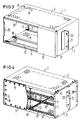
- FIG. 1 shows a housing part 1 which, together with a second housing part 1, indicated by dash-dotted lines, forms a housing of a subrack.
- the housing part 1 consists essentially of an L-shaped sheet metal with a longer horizontal leg 2 and a shorter vertical leg 3.
- the vertical leg 3 has at its end a strip 4 bent web, which in the same direction as the horizontal leg 2 points. It is provided with a series of screw holes 5 which are arranged at a distance which depends on the frequency prevailing in the subrack.
- a further row of screw holes 5 is provided, which extends parallel to the other row.
- the horizontal leg 2 is bent up to a short support web 6 on its front side.
- the back of the legs 2, 3 have inwardly bent fastening webs 7, which are also provided with screw holes 5 for screwing on a rear wall plate.
- the second housing part 1 is rotationally symmetrical to the first about a horizontal axis extending parallel to the legs 2, 3 arranged. This results in a rectangular housing in which the housing parts overlap in the area of the connecting webs 4 in such a way that the two rows of screw holes 5 in the webs 4 and at the ends of the long legs 2 overlap.
- the screw holes 5 are dimensioned such that the two housing parts can be mechanically and electrically securely connected to one another by self-tapping screws.
- the two same housing parts 1 are advantageously made of soft aluminum, which is perforated closely with air holes 8 in the region of the horizontal leg 2.
- the relatively large material thickness enables a narrow hole spacing without impairing the mechanical stability and the shielding effect.
- FIG. 2 shows the housing parts 1 in the assembled state with a rear wall plate 9 screwed to the fastening webs 7 and carrying vertically oriented web connectors 10.
- the rear wall plate 9 is designed as a multilayer printed circuit board which has a ground layer on its outside, which prevents interference radiation from passing through.
- the rear wall plate 9 is also fastened to the housing parts 1 with self-tapping screws 11. The heads of the screws 11 are contacted with the ground layers, so that a secure electrical connection occurs between the housing parts 1 and the ground layers.
- Horizontal support rails 12, along which rail-like guides 13 for retractable electrical assemblies 14 are held, extend along the horizontal legs 2.
- the guides 13 extend perpendicular to the mounting rails 12 from the front to the rear of the housing parts.
- the assembly is provided with a rear connector 15, which is contacted with the connector 10.
- the support rails 12 are fastened to the short vertical legs 3 of the housing parts 1 in a manner not shown.
- the support webs 6 are dimensioned so that they are supported with their free longitudinal edge on the front mounting rails 12, whereby the housing parts 1 are additionally stiffened on this side.
- a front cover 16 has edges 17 which are bent towards the rear and which grip around the housing parts 1 from the outside.
- Contact spring strips 18 are arranged between the edges 17 and the legs 2, 3 of the housing parts 1, which electrically connect the cover 16 to the housing parts 1.
- the contact spring strips also hold the cover 16 non-positively on the housing parts 1. They are held in a form-fitting manner on the inner sides of the edges 17 and are protected against damage from handling.
- Figures 2 and 3 show the subrack according to Figure 2 in a perspective view from the front ( Figure 2) and the back ( Figure 3).
- the mounting rails 12 have holding holes 19 for fastening the guides 13 for the assemblies 14.
- the short legs 3 of the housing parts 1 are provided along their front edge with a clamping tab 20 which is bounded to the outside and is spring-loaded behind by the contact spring strips 18 (FIG. 2) and helps to securely latch the cover 16 to the housing parts 1.
- On the vertical short legs 3 z. B. by spot welding bracket 21, which are provided with mounting holes 22 for attaching the rack to a cabinet frame.
- the trough-like design of the cover 16 with its edges 17 can also be seen.
- the rear wall plate 9 is screwed all round to the screw holes 5 of the fastening webs 7. It thereby stabilizes the housing parts 1 against deformation.
- the air holes 8 are distributed closely, so that good cooling of the modules 14 is possible.
Landscapes
- Engineering & Computer Science (AREA)
- Microelectronics & Electronic Packaging (AREA)
- Shielding Devices Or Components To Electric Or Magnetic Fields (AREA)
- Mounting Of Printed Circuit Boards And The Like (AREA)
Abstract
Claims (10)
- Porte-modules pour des modules électriques enfichables (14), comportant des parois latérales (par exemple 3) qui s'étendent parallèlement à ces modules et qui sont en tôle, ainsi que des moyens de fixation du porte-modules dans un bâti d'armoire, des tôles de protection (par exemple 2), qui sont en contact avec les parois latérales, étant disposées entre les parois latérales de la face supérieure et de la face inférieure du porte-modules, caractérisé le fait que les tôles de protection et les parois latérales sont des éléments constitutifs de deux parties de boîtier (1) coudées en forme de L, qui sont situées symétriquement en vis-à-vis l'une de l'autre et qui sont reliées entre elles à leurs extrémités et dont les branches (2,3), qui se rejoignent mutuellement forment les parois latérales et les tôles de protection, qu'au moins l'une des branches (3) possède, à son extrémité, une barrette (4) coudée en forme de bande, qui chevauche l'une (2) des branches qui se rejoignent, de l'autre partie de boîtier (1) et que les deux parties de boîtier (1) comportent, dans cette zone, une série de points de liaison.
- Porte-modules suivant la revendication 1, caractérisé par le fait que les parties de boîtier (1) comportent sur la face arrière, le long des branches (2,3), des barrettes de fixation (7) qui sont coudées à angle droit vers l'intérieur et qui comportent une multiplicité de points de fixation pour une plaque de paroi arrière (9).
- Porte-modules suivant la revendication 1 ou 2, caractérisé par le fait que des barrettes de support (6), qui sont coudées frontalement à angle droit, sont formées sur les parties de boîtier (1) le long de leur branche (2) horizontale.
- Porte-modules suivant la revendication 1, 2 ou 3, caractérisé par le fait que des guides en forme de rails (13) pour différents modules (14) sont retenus sur des rails horizontaux de support (12), qui s'étendent parallèlement à la face frontale du porte-modules le long des longues branches (2) supérieure et inférieure des parties de boîtier (1), et que les barrettes d'appui frontales (6) prennent appui sur les rails de support frontaux (12).
- Porte-modules suivant l'une des revendications précédentes, caractérisé par le fait que les branches horizontales (2) des parties de boîtier (1) sont perforées selon un réseau à mailles étroites.
- Porte-modules suivant l'une des revendications précédentes, caractérisé par le fait que les parties de boîtier (1) sont vissées l'une à l'autre au niveau de points de liaison et que la plaque de paroi arrière (9) est vissée sur les barrettes de fixation (7) situées sur la face arrière.
- Porte-modules suivant l'une des revendications précédentes, caractérisé par le fait que les parties de boîtier (1) sont en aluminium mou et sont reliées entre elles et à la plaque de paroi (9) par des vis autotaraudeuses (11).
- Porte-modules suivant la revendication 7, caractérisé par le fait que la plaque de paroi arrière (9) est réalisée sous la forme d'une plaquette à circuits imprimés, qui possède, sur la face extérieure du porte-module, au moins un point de masse, que la plaque de paroi arrière (9) est vissée au moyen des vis autotaraudeuses (1) sur la barrette de fixation (7) et que les vis (11) sont en contact avec le point de masse.
- Porte-modules suivant l'une des revendications précédentes, caractérisé par le fait que la face avant du porte-modules peut être fermée par un couvercle (16) semblable à une cuvette et dont les bords (17) entourent extérieurement les parties de boîtier (1) et que des bandes élastiques de contact (18) sont disposées entre les bords (17) et les parties de boîtier (1).
- Porte-modules suivant l'une des revendications précédentes, caractérisé par le fait que sur les branches (3) verticales des parties de boîtier (1) sont disposées des cornières de fixation (21) servant à fixer le porte-modules sur un châssis d'armoire.
Priority Applications (1)
| Application Number | Priority Date | Filing Date | Title |
|---|---|---|---|
| EP92903884A EP0573441B1 (fr) | 1991-02-28 | 1992-02-10 | Support blinde de composants electriques enfichables |
Applications Claiming Priority (4)
| Application Number | Priority Date | Filing Date | Title |
|---|---|---|---|
| EP91103030 | 1991-02-28 | ||
| EP91103030 | 1991-02-28 | ||
| EP92903884A EP0573441B1 (fr) | 1991-02-28 | 1992-02-10 | Support blinde de composants electriques enfichables |
| PCT/EP1992/000287 WO1992016093A1 (fr) | 1991-02-28 | 1992-02-10 | Support blinde de composants electriques enfichables |
Publications (2)
| Publication Number | Publication Date |
|---|---|
| EP0573441A1 EP0573441A1 (fr) | 1993-12-15 |
| EP0573441B1 true EP0573441B1 (fr) | 1995-05-10 |
Family
ID=8206468
Family Applications (1)
| Application Number | Title | Priority Date | Filing Date |
|---|---|---|---|
| EP92903884A Expired - Lifetime EP0573441B1 (fr) | 1991-02-28 | 1992-02-10 | Support blinde de composants electriques enfichables |
Country Status (5)
| Country | Link |
|---|---|
| EP (1) | EP0573441B1 (fr) |
| JP (1) | JPH06505128A (fr) |
| DE (1) | DE59202162D1 (fr) |
| WO (1) | WO1992016093A1 (fr) |
| ZA (1) | ZA921459B (fr) |
Families Citing this family (8)
| Publication number | Priority date | Publication date | Assignee | Title |
|---|---|---|---|---|
| SE503000C2 (sv) * | 1994-06-10 | 1996-03-11 | Ericsson Telefon Ab L M | Skenarrangemang |
| DE9412375U1 (de) | 1994-08-01 | 1994-09-22 | Siemens AG, 80333 München | Anordnung zum Kontaktieren von Gehäuseteilen eines elektrischen Gerätes |
| DE29507255U1 (de) * | 1995-05-02 | 1996-05-30 | Siemens AG, 80333 München | Baugruppenträger sowie Schrank mit einem derartigen Baugruppenträger |
| DE19821520C1 (de) * | 1998-05-13 | 1999-11-04 | Siemens Ag | Schirmeinrichtung für eine elektronische Baueinheit |
| WO1999059388A1 (fr) * | 1998-05-13 | 1999-11-18 | Siemens Aktiengesellschaft | Dispositif de blindage pour un support de modules electriques |
| DE19821522C1 (de) * | 1998-05-13 | 1999-06-24 | Siemens Ag | Schirmeinrichtung für einen elektrischen Baugruppenträger |
| ATE240631T1 (de) * | 1998-10-01 | 2003-05-15 | Rittal Electronic Systems Gmbh | Vorrichtung zur aufnahme von elektrischen flachbaugruppen, insbesondere baugruppenträger |
| DE50000605D1 (de) * | 1999-04-16 | 2002-11-07 | Siemens Ag | Schirmeinrichtung für einen elektrischen baugruppenträger |
Family Cites Families (4)
| Publication number | Priority date | Publication date | Assignee | Title |
|---|---|---|---|---|
| DE1976658U (de) * | 1967-08-16 | 1968-01-11 | Bosch Elektronik Photokino | Abschirmgehaeuse fuer hochfrequenzverstaerker. |
| CH511549A (fr) * | 1968-10-29 | 1971-08-31 | Academia Republicii Socialiste | Composition pour traiter les plantes utiles et procédé de sa préparation |
| DE3112595C2 (de) * | 1981-03-30 | 1983-06-16 | Siemens AG, 1000 Berlin und 8000 München | Rahmen für einschiebbare elektrische Baugruppen |
| DE3438702A1 (de) * | 1984-10-23 | 1986-04-24 | Licentia Patent-Verwaltungs-Gmbh, 6000 Frankfurt | Elektromagnetisch geschirmte kammer |
-
1992
- 1992-02-10 JP JP4503967A patent/JPH06505128A/ja active Pending
- 1992-02-10 EP EP92903884A patent/EP0573441B1/fr not_active Expired - Lifetime
- 1992-02-10 WO PCT/EP1992/000287 patent/WO1992016093A1/fr not_active Ceased
- 1992-02-10 DE DE59202162T patent/DE59202162D1/de not_active Expired - Fee Related
- 1992-02-27 ZA ZA921459A patent/ZA921459B/xx unknown
Also Published As
| Publication number | Publication date |
|---|---|
| DE59202162D1 (de) | 1995-06-14 |
| WO1992016093A1 (fr) | 1992-09-17 |
| EP0573441A1 (fr) | 1993-12-15 |
| JPH06505128A (ja) | 1994-06-09 |
| ZA921459B (en) | 1992-11-25 |
Similar Documents
| Publication | Publication Date | Title |
|---|---|---|
| EP0528240B1 (fr) | Panneau d'appareillage | |
| EP0415246B1 (fr) | Rack électronique | |
| WO1992016093A1 (fr) | Support blinde de composants electriques enfichables | |
| EP0596349B1 (fr) | Support pour installation électrique | |
| DE19644418C1 (de) | Baugruppenträger | |
| DE2413826A1 (de) | Zusammengesetzte schaltungstafeln fuer gedruckte schaltungen | |
| DE29619565U1 (de) | Baugruppenträger für Leiterplatten mit abgeschirmter Front- und Rückseite | |
| EP1172027A1 (fr) | Dispositif de blindage destine a un support de module electrique | |
| EP1121841B1 (fr) | Dispositif servant a recevoir des modules electriques plats, notamment des supports de modules | |
| DE19646481A1 (de) | Gehäuse für elektrische Komponenten und Baugruppen | |
| EP0589316B1 (fr) | Rack électronique | |
| AT409047B (de) | Vorrichtung zur erdung einer modular aufgebauten gehäuseeinheit | |
| DE4015926C1 (en) | Magazine for insertable electrical modules - has screening plate and side walls formed from two metal sheets bowed into U=shape | |
| DE29618629U1 (de) | Baugruppenträger | |
| DE3413862C2 (fr) | ||
| EP4618329A1 (fr) | Support de composants | |
| DE2714563C2 (de) | Baugruppenträger | |
| DE3508311C2 (fr) | ||
| DE3200729A1 (de) | Einrichtung zur befestigung von leiterplatten in einem traegerrahmen | |
| DE4302205C3 (de) | Einrichtung zum Reduzieren der Störstrahlung elektrischer Flachbaugruppen | |
| EP0284882A2 (fr) | Rack pour armoires de télécommunications | |
| DE9011202U1 (de) | Aufnahme für eine aus einem Leiterplattenpaket bestehende elektrische Baugruppe | |
| DE9115845U1 (de) | Baugruppenträger | |
| DE3504080C2 (fr) | ||
| DE29817536U1 (de) | Vorrichtung zur Aufnahme von elektrischen Flachbaugruppen, insbesondere Baugruppenträger |
Legal Events
| Date | Code | Title | Description |
|---|---|---|---|
| PUAI | Public reference made under article 153(3) epc to a published international application that has entered the european phase |
Free format text: ORIGINAL CODE: 0009012 |
|
| 17P | Request for examination filed |
Effective date: 19930701 |
|
| AK | Designated contracting states |
Kind code of ref document: A1 Designated state(s): BE CH DE FR GB IT LI NL SE |
|
| 17Q | First examination report despatched |
Effective date: 19940519 |
|
| GRAA | (expected) grant |
Free format text: ORIGINAL CODE: 0009210 |
|
| AK | Designated contracting states |
Kind code of ref document: B1 Designated state(s): BE CH DE FR GB IT LI NL SE |
|
| PG25 | Lapsed in a contracting state [announced via postgrant information from national office to epo] |
Ref country code: NL Free format text: LAPSE BECAUSE OF FAILURE TO SUBMIT A TRANSLATION OF THE DESCRIPTION OR TO PAY THE FEE WITHIN THE PRESCRIBED TIME-LIMIT Effective date: 19950510 Ref country code: IT Free format text: LAPSE BECAUSE OF FAILURE TO SUBMIT A TRANSLATION OF THE DESCRIPTION OR TO PAY THE FEE WITHIN THE PRE;WARNING: LAPSES OF ITALIAN PATENTS WITH EFFECTIVE DATE BEFORE 2007 MAY HAVE OCCURRED AT ANY TIME BEFORE 2007. THE CORRECT EFFECTIVE DATE MAY BE DIFFERENT FROM THE ONE RECORDED.SCRIBED TIME-LIMIT Effective date: 19950510 Ref country code: GB Effective date: 19950510 Ref country code: FR Effective date: 19950510 Ref country code: BE Effective date: 19950510 |
|
| REF | Corresponds to: |
Ref document number: 59202162 Country of ref document: DE Date of ref document: 19950614 |
|
| PG25 | Lapsed in a contracting state [announced via postgrant information from national office to epo] |
Ref country code: SE Effective date: 19950810 |
|
| EN | Fr: translation not filed | ||
| NLV1 | Nl: lapsed or annulled due to failure to fulfill the requirements of art. 29p and 29m of the patents act | ||
| GBV | Gb: ep patent (uk) treated as always having been void in accordance with gb section 77(7)/1977 [no translation filed] |
Effective date: 19950510 |
|
| PG25 | Lapsed in a contracting state [announced via postgrant information from national office to epo] |
Ref country code: LI Effective date: 19960229 Ref country code: CH Effective date: 19960229 |
|
| PLBE | No opposition filed within time limit |
Free format text: ORIGINAL CODE: 0009261 |
|
| STAA | Information on the status of an ep patent application or granted ep patent |
Free format text: STATUS: NO OPPOSITION FILED WITHIN TIME LIMIT |
|
| 26N | No opposition filed | ||
| REG | Reference to a national code |
Ref country code: CH Ref legal event code: PL |
|
| PG25 | Lapsed in a contracting state [announced via postgrant information from national office to epo] |
Ref country code: DE Effective date: 19961101 |