EP0573531B1 - Train pour planche a roulettes - Google Patents
Train pour planche a roulettes Download PDFInfo
- Publication number
- EP0573531B1 EP0573531B1 EP92906137A EP92906137A EP0573531B1 EP 0573531 B1 EP0573531 B1 EP 0573531B1 EP 92906137 A EP92906137 A EP 92906137A EP 92906137 A EP92906137 A EP 92906137A EP 0573531 B1 EP0573531 B1 EP 0573531B1
- Authority
- EP
- European Patent Office
- Prior art keywords
- truck
- locking
- deck
- pivotal
- skateboard
- Prior art date
- Legal status (The legal status is an assumption and is not a legal conclusion. Google has not performed a legal analysis and makes no representation as to the accuracy of the status listed.)
- Expired - Lifetime
Links
- 125000006850 spacer group Chemical group 0.000 description 2
- 230000009977 dual effect Effects 0.000 description 1
- 239000012858 resilient material Substances 0.000 description 1
- 239000007787 solid Substances 0.000 description 1
Images


Classifications
-
- A—HUMAN NECESSITIES
- A63—SPORTS; GAMES; AMUSEMENTS
- A63C—SKATES; SKIS; ROLLER SKATES; DESIGN OR LAYOUT OF COURTS, RINKS OR THE LIKE
- A63C17/00—Roller skates; Skate-boards
- A63C17/01—Skateboards
-
- A—HUMAN NECESSITIES
- A63—SPORTS; GAMES; AMUSEMENTS
- A63C—SKATES; SKIS; ROLLER SKATES; DESIGN OR LAYOUT OF COURTS, RINKS OR THE LIKE
- A63C17/00—Roller skates; Skate-boards
- A63C17/01—Skateboards
- A63C17/011—Skateboards with steering mechanisms
- A63C17/012—Skateboards with steering mechanisms with a truck, i.e. with steering mechanism comprising an inclined geometrical axis to convert lateral tilting of the board in steering of the wheel axis
-
- A—HUMAN NECESSITIES
- A63—SPORTS; GAMES; AMUSEMENTS
- A63C—SKATES; SKIS; ROLLER SKATES; DESIGN OR LAYOUT OF COURTS, RINKS OR THE LIKE
- A63C17/00—Roller skates; Skate-boards
- A63C17/01—Skateboards
- A63C17/014—Wheel arrangements
- A63C17/015—Wheel arrangements with wheels arranged in two pairs
-
- A—HUMAN NECESSITIES
- A63—SPORTS; GAMES; AMUSEMENTS
- A63C—SKATES; SKIS; ROLLER SKATES; DESIGN OR LAYOUT OF COURTS, RINKS OR THE LIKE
- A63C2203/00—Special features of skates, skis, roller-skates, snowboards and courts
- A63C2203/52—Direct actuation of steering of roller skate or skateboards, e.g. by a foot plate
Definitions
- the present invention relates to a truck for a skateboard.
- Conventional skateboards typically have a deck and pair of trucks, one located at the front and one at the rear of the deck. Each of these trucks comprises two wheels and is rigidly mounted on the deck.
- the truck of the present invention as claimed in claim 1 permits advanced riding manoeuvres to be more easily performed by a rider.
- a rider is able to get a skateboard provided with a truck in accordance with the claimed invention into a forward motion by shifting his/her weight from side to side, without touching the ground with his/her foot.
- US-A-4,955,626 discloses a very special type of skateboard which is said to be highly manoeuvrable in comparison with conventional skateboards.
- This prior art skateboard includes two footboards instead of a conventional deck, with each footboard consisting of a foot platform and a truck comprising two spaced apart wheels fixed to the platform.
- the two footboards are linked by a spacer element that is pivotably connected to each of said trucks.
- the two footboards are pivotable relatively to said spacer element, but the trucks disclosed in US-A-4,955,626 are not pivotably mounted on their respective foot platform and are therefore structurally and functionally quite different from a truck of the present invention.
- a truck for a skateboard wherein in a first mode of operation said pivotal member means is pivotable such that said truck is movable in a to and fro manner, and in a second mode of operation said truck is lockable against said to and fro movement by said locking means.
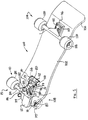
- skateboard 100 incorporating a skateboard truck 10 in accordance with an embodiment of the present invention.
- the truck 10 is provided at the front of the skateboard 100.
- the skateboard 100 itself comprises a deck 102 and another (rear) truck 104 both of which may be of conventional form.
- the deck 102 may be provided with an upwardly inclined offset portion 106 at its rear end and a rounded tapered portion 108 near its front end.
- the skateboard truck 10 comprises a pivotal member 12 which carries the rest of the truck 10 including a wheel assembly 13, and a locking mechanism 14.
- the rest of the truck 10 is attached to the pivotal member 12 by bolts 15.
- the pivotal member 12 is arranged to be connected to the deck 102 of the skateboard 100.
- a pivotal connection 16 is arranged to connect the pivotal member 12 to the deck 102 such that the pivotal member 12 is able to perform pivotal motion relative to the deck 102.
- the pivotal connection 16 is provided near one end of the pivotal member 12 and the rest of the truck 10 is provided near the other end of the pivotal member 12.
- the pivotal connection 16 is arranged to be connected to the forward part of the deck 102, with the pivotal member 12 extending rearwardly.
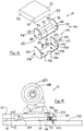
- the pivotal connection 16 shown in Figure 2 comprises a short shaft or pin 18 which is arranged to be connected to the deck 102.
- the shaft 18 has a circular plate 20 connected at the end thereof in a transverse manner.
- the circular plate 20 has a circular groove 22 near the periphery thereof to accommodate a first set of ball bearings 24.
- a circular plate 26 is supported in the pivotal member 12 by a web 28 that extends between upper and lower walls 30 and 31, respectively, of the pivotal member 12.
- the pivotal member 12 is also provided with an outer wall 32 which extends between the upper and lower walls 30 and 31.
- the circular plate 26 has a circular groove 34 to accommodate the first set of ball bearings 24.
- the circular grooves 22 and 34 are in registration such that they form upper and lower circular grooves, respectively, to retain the first set of ball bearings 24.
- a further circular groove 36 is provided in the plate 26 adjacent the circular groove 34 (but on the opposite side of the circular plate 26) to accommodate a second set of ball bearings 38.
- Another circular plate 40 is provided above the second set of ball bearings 38 and is provided with a circular groove 42 to accommodate the second set of ball bearings 38.
- the circular grooves 36 and 42 are in registration such that they form lower and upper circular grooves, respectively, to retain the second set of ball bearings 38.
- the circular plate 40 is connected to the deck 102 by portions 43a and 43b.
- the upper wall 30 is provided with an opening to accommodate the shaft 18 and portion 43a.
- pivotal member 12 pivots via the pivotal connection 16 only the circular plate 26, web 28 and walls 30, 31 and 32 move. The other parts of the pivotal connection 16 do not move.
- the pivotal connection 16 permits the pivotal member 12 to pivot smoothly due to the dual arrangement of ball bearings 38 and 24 above and below, respectively, the circular plate 26.
- the locking mechanism 14 comprises a bracket 44, arranged to be connected to the deck 102, and a locking member 46 pivotally held by the bracket 44.
- the bracket 44 comprises a base 48 and two side portions 50 extending therefrom.
- the base 48 is provided with apertures 52 such that screws 54 may be passed therethrough and into the deck 102 to connect the bracket 44 to the undersurface of the deck 102.
- the base 48 is also provided with a cut out 56.
- the two side portions 50 are each provided with a hole 58 near one of their corners. These holes 58 are aligned.
- the inside faces 59 of the side portions 50 are each provided a pin 60 near a curved edge 62 thereof.
- the locking member 46 comprises a base 64 and two side portions 66 extending therefrom.
- the two side portions 66 are each provided with a pin 68 extending from their outer faces 69, near one of their corners.
- the pins 68 are aligned.
- the sides 66 are each provided with a hole 70.
- a locking block 72 is positioned between the two side portions 66 near straight edges 74 of the side portions 66 on the base 64.
- the side portions 66 are provided with curved edges 76.
- the holes 70 are provided near the curved edges 76.
- the pins 68 of the locking member 46 locate in the holes 58 of the bracket 44 such that the locking member 46 is pivotal relative to the bracket 44.
- the pins 60 on the side portions 50 of the bracket 44 may engage in the holes 70 of the side portions 66 of the locking member 46 to retain the locking member 46 in a non-locking position.
- the pivotal member 12 In the non-locking position, the pivotal member 12 is free to pivot and so the truck 10 is able to pivot.
- the pivotal member 12 is provided with a pin 77 extending from each side 78 thereof.
- the pins 77 engage in the holes 70 in the side portions 66 of the locking member 46 when the locking member 46 is pivoted to its locking position to retain and locking member 46 in its locking position.
- the pivotal member 12 In the locking position, the pivotal member 12 is unable to pivot, thereby preventing to and fro movement of the truck 10. This is because the side portions 66 abut with the sides 78 of the pivotal member 12 to prevent any sideways, or pivotal, movement of the pivotal member 12. Further, the locking block 72 abuts with the pivotal member 12, being positioned between the pivotal member 12 and the deck 102, to stabilize the pivotal member 12.
- the cut-out 56 is provided in the base 48 to enable the locking member 46 to be easily pivoted from the non-locking position to the locking position by an operator using his/her finger to flick the locking member 46 into position.
- the locking block 72 has a rounded edge 73 to facilitate movement of the locking member 46 to and from the locking position past the edge 75 of the pivotal member 12. (As an alternative, the edge 75 of the pivotal member 12 may be rounded, and the edge 73 of the locking block 72 may be straight-edged.)
- Stop members 79 may be provided to limit the movement of the pivotal member 12.
- the stop members 79 are arranged to be connected to the underside of the deck 102 near the front end thereof, on respective sides of the pivotal member 12.
- the remainder of the truck 10 may be of conventional form.
- the truck 10 may further comprise a mounting plate 80 connecting the remainder of the truck 10 to the pivotal member 102 by way of bolts 81; resilient portions 82 on either side of a collar 83 extending from a casing 84; the casing 84 encloses the axle-bearing shaft which carries the axles upon which the wheels 85 are mounted which together make up the wheel assembly 13; a bolt 86 extending through he resilient portions 82, collar 83, a sleeve 87 and into the mounting plate 80; along with nuts 88 to retain the wheels 85 on the truck 10.
- truck 104 may be of conventional form.
- the truck 104 may comprise a mounting plate 110 connecting the truck 104 to the deck 102 by way of bolts 112 with an intermediate block 116 of resilient material, along with nuts 118 to retain the wheels 120 on the truck 104.
- the other parts of the truck 104 are obscured in Figure 1, but it will be understood that these may be of conventional form, as hereinabove stated.
- the pivotal member 12 In the locking position of the locking member 46 of the locking mechanism 14 of the truck 10, the pivotal member 12 is unable to pivot.
- the truck 10 is thus locked against any to and fro side to side movement.
- the truck 10 functions as a conventional truck and the skateboard 100 may be ridden as a conventional skateboard.
- the pivotal member 12 When the locking member 46 is moved to its non-locking position, the pivotal member 12 is able to pivot by way of the pivotal connection 16 and the truck 10 is able to move in a pivotal, to and fro, side to side manner.
- a rider When the non-locking position of the locking member 46 is engaged, a rider can stand on the deck 102 and by shifting his/her weight from side to side is able to get the skateboard 100 into motion such that it moves in a forward direction. The rider can do this without touching the ground with his/her foot.
- the side to side movement of the rider causes the pivotal member 12 to pivot back and forth between the stop members 79 via the connection 16. This causes the truck 10 to also move in a corresponding to and fro swinging manner. This causes the skateboard 100 to move in a forward direction.
- the truck 10 of the present invention also permits the skateboard 100 to be forwardly moved along an incline.
- the skateboard truck of the present invention permits a rider to perform advanced riding manoeuvres on a skateboard.
Landscapes
- Motorcycle And Bicycle Frame (AREA)
Abstract
Claims (15)
- Train pour planche à roulettes comprenant un ensemble de roulettes (13) avec au moins deux roulettes espacées (85),
caractérisé parun élément pivotant allongé (12) pour monter en pivotement ledit ensemble de roulettes (13) sur une planche (102), ledit ensemble de roulettes étant supporté par une première extrémité dudit élément pivotant allongé (12) et une liaison pivotante (16) reliant ladite deuxième extrémité dudit élément pivotant allongé (12) à la planche (102), afin que ledit ensemble de roulettes soit écarté de ladite liaison pivotante (16) et puisse exécuter un mouvement pivotant par rapport à la planche (102), etdes éléments d'arrêt (79) pour limiter le mouvement pivotant dudit élément pivotant (12), lesdits éléments d'arrêt (79) étant disposés de manière à ce que ledit élément pivotant (12) puisse osciller suivant un mouvement de va-et-vient entre lesdits éléments d'arrêt, dans lequel le train puisse être rattaché à la planche (102) afin que ledit ensemble de roulettes (13) soit toujours situé, dans le sens de déplacement, à l'arrière de ladite liaison pivotante (16). - Train selon la revendication 1, caractérisé en ce que ladite liaison pivotante (16) comprendun axe (18) disposé de manière à être rattaché à ladite planche (102);une première plaque (40) disposée de manière à être rattachée à la planche (102),une deuxième plaque (26) rattachée audit élément pivotant (12),un premier jeu de roulements à billes (24) installés entre lesdites première et deuxième plaques (40, 26) de telle sorte que ledit élément pivotant (12) soit pivotant par l'intermédiaire de ladite liaison pivotante (16) par rapport à la planche (102),une troisième plaque (20) rattachée audit axe (18), etun deuxième jeu de roulements à billes (38) installés entre lesdites deuxième et troisième plaques (26, 20).
- Train selon la revendication 2, caractérisé en ce que lesdites première, deuxième et troisième plaques (40, 26, 20) sont équipées de rainures pour recevoir lesdits premier et deuxième jeux de roulement à billes (24, 38).
- Train selon l'une quelconque des revendications 1 à 3, caractérisé par un moyen de blocage (14) pour bloquer ledit élément pivotant (12) par rapport à ladite liaison pivotante (16), afin que ledit élément pivotant (12) ne puisse se déplacer suivant ledit mouvement de va-et-vient.
- Train selon la revendication 4, caractérisé en ce que ledit moyen de blocage (14) comprend un élément de blocage (46) mobile entre une première position non bloquée, dans un premier mode de fonctionnement, et une deuxième position bloquée, dans un deuxième mode de fonctionnement, deuxième mode de fonctionnement dans lequel ledit élément de blocage (46) s'engage dans ledit élément pivotant (12).
- Train selon la revendication 5, caractérisé en ce que ledit élément de blocage (46) comprend des parties latérales (66) qui se trouvent contiguës aux côtés respectifs (78) dudit élément pivotant (12) dans ladite position de blocage.
- Train selon la revendication 5 ou 6, caractérisé en ce que ledit élément de blocage (46) est installé à proximité de ladite première extrémité dudit élément pivotant (12).
- Train selon l'une quelconque des revendications 5 à 7, caractérisé en ce que ledit moyen de blocage comprend une cale de blocage (72) qui est disposée pour s'emboîter entre la planche (102) et ledit élément pivotant (12) dans ladite deuxième position de blocage.
- Train selon l'une quelconque des revendications 5 à 8, caractérisé en ce que ledit moyen de blocage comprend une équerre (44) disposée pour être rattachée à ladite planche (102), dans lequel ledit élément de blocage (46) est maintenu en pivotement par ladite équerre (44).
- Train selon l'une quelconque des revendications 5 à 9, caractérisé en ce qu'un premier moyen d'engagement (77) est installé sur ledit élément pivotant (12), un deuxième moyen d'engagement (70) est installé sur des parties latérales (66) dudit élément de blocage (46), lesdites parties latérales (66) se trouvant contiguës auxdits côtés dudit élément pivotant (12) dans ladite position de blocage, et dans lesquels lesdits premier et deuxième moyens d'engagement (77, 70) s'engagent pour retenir de manière déblocable ledit élément de blocage (46) dans ladite deuxième position de blocage.
- Train selon la revendication 10, caractérisé en ce que ledit élément de blocage (46) et ladite équerre (44) sont respectivement équipés d'un deuxième et d'un troisième moyen d'engagement (70, 60) qui s'engagent pour retenir de manière déblocable ledit élément de blocage (46) dans ladite première position de non blocage.
- Train selon la revendication 9, caractérisé en ce que ledit élément de blocage (46) et ladite équerre (44) sont respectivement équipés d'un deuxième et d'un troisième moyen d'engagement (70, 60), et ledit deuxième moyen d'engagement (60) est muni sur les parties latérales (66) dudit élément de blocage (46) et ledit troisième moyen d'engagement (70) est muni sur les parties latérales (50) de ladite équerre (44), lesdites parties latérales respectives se trouvant contiguës les unes les autres dans ladite première position de non blocage.
- Train selon l'une quelconque des revendications 8 à 12, caractérisé en ce que ladite cale de blocage (72) ou ledit élément pivotant (12) est équipé d'un bord arrondi (73) pour faciliter le mouvement de ladite cale de blocage sur un bord dudit élément pivotant (12).
- Dispositif pour réaliser des manoeuvres de conduite comprenant:une planche allongée (102) pour supporter un conducteur,un train arrière (104) avec deux roulettes espacées (120), ledit train arrière (104) étant monté, dans le sens de déplacement, dans la partie arrière de ladite planche (102), caractérisé parun train avant (10) selon l'une quelconque des revendications 1 à 13, ledit train avant (10) étant monté, dans le sens de déplacement, dans la partie avant de ladite planche (102), de manière à ce qu'un conducteur, prenant place sur ladite planche et déplaçant son poids d'un côté vers l'autre, puisse réaliser un mouvement de va-et-vient dudit élément pivotant (12), en conséquence de quoi ledit conducteur peut propulser le dispositif dans une direction avant sans toucher le sol avec son pied.
- Planche à roulettes caractérisée parun train (10) selon l'une quelconque des revendications 1 à 13, ledit train étant monté sur ladite planche à roulettes de telle sorte qu'un conducteur prenant place sur ladite planche à roulettes et déplaçant son poids d'un côté vers l'autre puisse produire un mouvement de va-et-vient dudit élément pivotant (12), en conséquence de quoi ledit conducteur peut propulser le dispositif dans une direction avant sans toucher le sol avec son pied.
Applications Claiming Priority (3)
| Application Number | Priority Date | Filing Date | Title |
|---|---|---|---|
| AUPK491391 | 1991-03-01 | ||
| AU4913/91 | 1991-03-01 | ||
| PCT/AU1992/000089 WO1992015377A1 (fr) | 1991-03-01 | 1992-02-28 | Train pour planche a roulettes |
Publications (3)
| Publication Number | Publication Date |
|---|---|
| EP0573531A1 EP0573531A1 (fr) | 1993-12-15 |
| EP0573531A4 EP0573531A4 (en) | 1994-05-18 |
| EP0573531B1 true EP0573531B1 (fr) | 1997-05-02 |
Family
ID=3775259
Family Applications (1)
| Application Number | Title | Priority Date | Filing Date |
|---|---|---|---|
| EP92906137A Expired - Lifetime EP0573531B1 (fr) | 1991-03-01 | 1992-02-28 | Train pour planche a roulettes |
Country Status (5)
| Country | Link |
|---|---|
| US (1) | US5522620A (fr) |
| EP (1) | EP0573531B1 (fr) |
| CA (1) | CA2105290C (fr) |
| DE (1) | DE69219463T2 (fr) |
| WO (1) | WO1992015377A1 (fr) |
Families Citing this family (28)
| Publication number | Priority date | Publication date | Assignee | Title |
|---|---|---|---|---|
| US5755160A (en) * | 1994-07-21 | 1998-05-26 | Blufordcraving; Charles Nathaniel | Rotating floor for motor vehicles |
| EP0747100A3 (fr) * | 1995-06-09 | 1997-09-17 | Karl Kroher | Dispositif pour rouler |
| US6374645B1 (en) | 1999-03-15 | 2002-04-23 | Spoonfish, Inc. | Security locks |
| US6422048B1 (en) | 1999-03-15 | 2002-07-23 | Spoonfish, Inc. | Snowboard security locks |
| US6318739B1 (en) * | 1999-05-27 | 2001-11-20 | Albert Lucien Fehn, Jr. | Suspension for a skateboard |
| US6315312B1 (en) | 1999-10-27 | 2001-11-13 | Juan L. Reyes | Truck for a skateboard |
| USD439945S1 (en) | 2000-03-16 | 2001-04-03 | Tracy Scott Kent | Pneumatic compression strut skateboard truck |
| US6793224B2 (en) | 2001-03-08 | 2004-09-21 | Carver Skateboards | Truck for skateboards |
| USD479868S1 (en) | 2002-02-14 | 2003-09-23 | Ojeda, Iii Felix | Skateboard truck guard |
| US20040041360A1 (en) * | 2002-08-29 | 2004-03-04 | Lukoszek Benjamin Shane | Truck assemblies for skateboards |
| US7121566B2 (en) * | 2003-07-15 | 2006-10-17 | Mcclain Nathan Myles | Skateboard suspension system |
| US7150460B2 (en) * | 2003-09-09 | 2006-12-19 | Alfred Williams | Skateboard truck |
| US7159879B2 (en) * | 2004-11-02 | 2007-01-09 | Jeffrey Cole | Braking and steering system for a truck, wheeled platform, skateboard or vehicle |
| US7070193B2 (en) * | 2004-09-04 | 2006-07-04 | Masashi Yamaguchi | Skateboard truck mounting system |
| US7413200B2 (en) * | 2006-01-09 | 2008-08-19 | Horn Bradford E | Skateboard truck with single-pin, pivotal, reversible attachment between axel and base plate, and means of improving a user's shredding capabilities through use of the skateboard truck with single-pin, pivotal attachment between axel and base plate |
| US8079604B2 (en) * | 2009-05-28 | 2011-12-20 | Surfskate Industries, Llc | Skateboard providing substantial freedom of movement of the front truck assembly |
| IT1394607B1 (it) | 2009-06-08 | 2012-07-05 | Bolditalia S R L | Perfezionamento negli sci o tavola su ruote. |
| US20110221150A1 (en) * | 2009-09-16 | 2011-09-15 | Brock Harris | Skateboard deck having adjustable truck mounting system |
| US10494050B2 (en) | 2014-12-01 | 2019-12-03 | Radio Flyer Inc. | Steering mechanism for scooter |
| USD736861S1 (en) | 2014-12-01 | 2015-08-18 | Radio Flyer Inc. | Scooter |
| USD756465S1 (en) | 2015-03-06 | 2016-05-17 | Radio Flyer Inc. | Scooter |
| DE102016107640B3 (de) | 2016-04-25 | 2017-07-13 | Stephan Augustin | Skateboard-Achsbaugruppe und Skateboard |
| US10864430B2 (en) | 2017-07-28 | 2020-12-15 | D&D Broadcast Inc. | Truck carrying adapter for skateboard |
| USD882011S1 (en) * | 2017-12-28 | 2020-04-21 | Performance Sk8 Holding, Inc | Part of skateboards |
| JP6578520B2 (ja) * | 2018-02-22 | 2019-09-25 | 株式会社アトラスオート | スケートボード |
| WO2019165493A1 (fr) * | 2018-03-01 | 2019-09-06 | Streetboardz International Pty Ltd | Bogie de planches à roulettes |
| AU2019204565B2 (en) | 2018-07-27 | 2021-09-30 | Waterborne Skateboards, Inc. | Truck carrying adapter for skateboard |
| US12194369B2 (en) | 2022-07-22 | 2025-01-14 | Waterborne Skateboards Inc. | Skateboard truck with adjustable plane of rotation |
Family Cites Families (21)
| Publication number | Priority date | Publication date | Assignee | Title |
|---|---|---|---|---|
| US1269107A (en) * | 1918-01-09 | 1918-06-11 | John E Annis | Juvenile vehicle. |
| US1467453A (en) * | 1922-04-18 | 1923-09-11 | Remacle Edmond | Caster for toys |
| CH113378A (fr) * | 1925-04-03 | 1926-05-17 | Albert Kustner | Patin à roulettes. |
| US1809609A (en) * | 1928-01-06 | 1931-06-09 | Giles M Turner | Caster |
| US2114586A (en) * | 1936-10-16 | 1938-04-19 | Charles Bond | Caster control means for movable trucks and the like |
| US2424072A (en) * | 1944-12-18 | 1947-07-15 | Samuel M Allred | Roller skate |
| US2542829A (en) * | 1945-01-15 | 1951-02-20 | Alan E Murray | Skate |
| US2632652A (en) * | 1950-05-09 | 1953-03-24 | Wintercorn Albert | Roller skate |
| US3235282A (en) * | 1965-02-09 | 1966-02-15 | Louis D Bostick | Skate board provided with longitudinally adjustable wheel carriage units |
| US3505878A (en) * | 1968-03-18 | 1970-04-14 | Edward W Moll | Speed and distance indicator for a ski device |
| US3771811A (en) * | 1972-08-16 | 1973-11-13 | Campos Bueno A De | Child {40 s coaster |
| US4114232A (en) * | 1977-12-01 | 1978-09-19 | Shin Nihon Koku Seibi K.K. | Caster with braking mechanism |
| US4202559A (en) * | 1978-08-10 | 1980-05-13 | Piazza John Jr | Skateboard |
| US4228928A (en) * | 1978-10-25 | 1980-10-21 | Northwest Sanitation Products, Inc. | Bottle with a clip for suspending the bottle in inverted position |
| ES291359U (es) * | 1985-12-28 | 1986-12-16 | Berenguer Hermanos, S.A. | Monopatin radiocontrolado de juguete con muneco incorporado. |
| US4776604A (en) * | 1986-05-14 | 1988-10-11 | Valdez Elva R | Steerable platformed vehicle for play or industrial use |
| US4775162A (en) * | 1987-07-24 | 1988-10-04 | Sun Craft Industrial Co., Ltd. | Swingable skateboard |
| FR2625688B1 (fr) * | 1988-01-12 | 1991-06-07 | Barachet Jacques | Planche a roulettes a deux roues en tandem |
| US4955626A (en) * | 1988-01-28 | 1990-09-11 | Smith Eric O M | Skateboards |
| US5052702A (en) * | 1988-08-29 | 1991-10-01 | Chan David M | Toy skateboard with steerable truck assemblies |
| US5263725A (en) * | 1992-02-24 | 1993-11-23 | Daniel Gesmer | Skateboard truck assembly |
-
1992
- 1992-02-28 US US08/108,674 patent/US5522620A/en not_active Expired - Fee Related
- 1992-02-28 DE DE69219463T patent/DE69219463T2/de not_active Expired - Fee Related
- 1992-02-28 EP EP92906137A patent/EP0573531B1/fr not_active Expired - Lifetime
- 1992-02-28 CA CA002105290A patent/CA2105290C/fr not_active Expired - Fee Related
- 1992-02-28 WO PCT/AU1992/000089 patent/WO1992015377A1/fr not_active Ceased
Also Published As
| Publication number | Publication date |
|---|---|
| CA2105290C (fr) | 2004-02-10 |
| CA2105290A1 (fr) | 1992-09-02 |
| DE69219463T2 (de) | 1997-11-13 |
| DE69219463D1 (de) | 1997-06-05 |
| US5522620A (en) | 1996-06-04 |
| EP0573531A1 (fr) | 1993-12-15 |
| WO1992015377A1 (fr) | 1992-09-17 |
| EP0573531A4 (en) | 1994-05-18 |
Similar Documents
| Publication | Publication Date | Title |
|---|---|---|
| EP0573531B1 (fr) | Train pour planche a roulettes | |
| US6860512B2 (en) | Utility motor vehicle with carrier | |
| US4403673A (en) | Powered vehicle | |
| EP1710119B1 (fr) | Siège pivotant | |
| EP1042039B1 (fr) | Planche a roulettes | |
| CA2125172C (fr) | Vehicule a quatre roues motrices orientables | |
| US4993733A (en) | Three wheeled recumbent cycle | |
| US6634663B2 (en) | Wheelchair propulsion kit | |
| US6270096B1 (en) | Steerable in-line skateboard | |
| EP0477592B1 (fr) | Roue pivotante pour chariot | |
| WO2010057113A1 (fr) | Planche à roulettes | |
| US4145065A (en) | Roller skate scooter | |
| GB2464676A (en) | Skateboard with inclined steering axis | |
| US20050212246A1 (en) | Compact foldable skateboard | |
| CA2471476A1 (fr) | Vehicule nival | |
| US3961810A (en) | Bicycle safety and conversion wheel | |
| US3206223A (en) | Tricycle with locking caster wheel | |
| US20020017768A1 (en) | Rollerboard | |
| US3857583A (en) | Occupant propelled quadracycle | |
| WO1995008449A1 (fr) | Roulettes | |
| WO2019165493A1 (fr) | Bogie de planches à roulettes | |
| US5540308A (en) | Parking lock for vehicle | |
| WO1996026858A1 (fr) | Luge a roulettes | |
| CN213057349U (zh) | 漂移车 | |
| WO2002002394A1 (fr) | Patinette |
Legal Events
| Date | Code | Title | Description |
|---|---|---|---|
| PUAI | Public reference made under article 153(3) epc to a published international application that has entered the european phase |
Free format text: ORIGINAL CODE: 0009012 |
|
| 17P | Request for examination filed |
Effective date: 19930927 |
|
| AK | Designated contracting states |
Kind code of ref document: A1 Designated state(s): DE FR GB IT |
|
| A4 | Supplementary search report drawn up and despatched | ||
| AK | Designated contracting states |
Kind code of ref document: A4 Designated state(s): DE FR GB IT |
|
| 17Q | First examination report despatched |
Effective date: 19950425 |
|
| GRAG | Despatch of communication of intention to grant |
Free format text: ORIGINAL CODE: EPIDOS AGRA |
|
| GRAH | Despatch of communication of intention to grant a patent |
Free format text: ORIGINAL CODE: EPIDOS IGRA |
|
| GRAH | Despatch of communication of intention to grant a patent |
Free format text: ORIGINAL CODE: EPIDOS IGRA |
|
| GRAA | (expected) grant |
Free format text: ORIGINAL CODE: 0009210 |
|
| AK | Designated contracting states |
Kind code of ref document: B1 Designated state(s): DE FR GB IT |
|
| REF | Corresponds to: |
Ref document number: 69219463 Country of ref document: DE Date of ref document: 19970605 |
|
| ET | Fr: translation filed | ||
| PLBE | No opposition filed within time limit |
Free format text: ORIGINAL CODE: 0009261 |
|
| STAA | Information on the status of an ep patent application or granted ep patent |
Free format text: STATUS: NO OPPOSITION FILED WITHIN TIME LIMIT |
|
| 26N | No opposition filed | ||
| REG | Reference to a national code |
Ref country code: GB Ref legal event code: IF02 |
|
| PGFP | Annual fee paid to national office [announced via postgrant information from national office to epo] |
Ref country code: FR Payment date: 20040210 Year of fee payment: 13 |
|
| PGFP | Annual fee paid to national office [announced via postgrant information from national office to epo] |
Ref country code: GB Payment date: 20040225 Year of fee payment: 13 |
|
| PGFP | Annual fee paid to national office [announced via postgrant information from national office to epo] |
Ref country code: DE Payment date: 20040311 Year of fee payment: 13 |
|
| PG25 | Lapsed in a contracting state [announced via postgrant information from national office to epo] |
Ref country code: IT Free format text: LAPSE BECAUSE OF NON-PAYMENT OF DUE FEES;WARNING: LAPSES OF ITALIAN PATENTS WITH EFFECTIVE DATE BEFORE 2007 MAY HAVE OCCURRED AT ANY TIME BEFORE 2007. THE CORRECT EFFECTIVE DATE MAY BE DIFFERENT FROM THE ONE RECORDED. Effective date: 20050228 Ref country code: GB Free format text: LAPSE BECAUSE OF NON-PAYMENT OF DUE FEES Effective date: 20050228 |
|
| PG25 | Lapsed in a contracting state [announced via postgrant information from national office to epo] |
Ref country code: DE Free format text: LAPSE BECAUSE OF NON-PAYMENT OF DUE FEES Effective date: 20050901 |
|
| GBPC | Gb: european patent ceased through non-payment of renewal fee |
Effective date: 20050228 |
|
| PG25 | Lapsed in a contracting state [announced via postgrant information from national office to epo] |
Ref country code: FR Free format text: LAPSE BECAUSE OF NON-PAYMENT OF DUE FEES Effective date: 20051031 |
|
| REG | Reference to a national code |
Ref country code: FR Ref legal event code: ST Effective date: 20051031 |