EP0573727A1 - Métier à tisser à pinces - Google Patents
Métier à tisser à pinces Download PDFInfo
- Publication number
- EP0573727A1 EP0573727A1 EP92810455A EP92810455A EP0573727A1 EP 0573727 A1 EP0573727 A1 EP 0573727A1 EP 92810455 A EP92810455 A EP 92810455A EP 92810455 A EP92810455 A EP 92810455A EP 0573727 A1 EP0573727 A1 EP 0573727A1
- Authority
- EP
- European Patent Office
- Prior art keywords
- warp threads
- support
- rapier
- weaving machine
- warp
- Prior art date
- Legal status (The legal status is an assumption and is not a legal conclusion. Google has not performed a legal analysis and makes no representation as to the accuracy of the status listed.)
- Granted
Links
Images

Classifications
-
- D—TEXTILES; PAPER
- D03—WEAVING
- D03D—WOVEN FABRICS; METHODS OF WEAVING; LOOMS
- D03D47/00—Looms in which bulk supply of weft does not pass through shed, e.g. shuttleless looms, gripper shuttle looms, dummy shuttle looms
- D03D47/12—Looms in which bulk supply of weft does not pass through shed, e.g. shuttleless looms, gripper shuttle looms, dummy shuttle looms wherein single picks of weft thread are inserted, i.e. with shedding between each pick
- D03D47/20—Constructional features of the thread-engaging device on the inserters
- D03D47/23—Thread grippers
- D03D47/233—Carrying grippers
-
- D—TEXTILES; PAPER
- D03—WEAVING
- D03D—WOVEN FABRICS; METHODS OF WEAVING; LOOMS
- D03D47/00—Looms in which bulk supply of weft does not pass through shed, e.g. shuttleless looms, gripper shuttle looms, dummy shuttle looms
- D03D47/12—Looms in which bulk supply of weft does not pass through shed, e.g. shuttleless looms, gripper shuttle looms, dummy shuttle looms wherein single picks of weft thread are inserted, i.e. with shedding between each pick
- D03D47/20—Constructional features of the thread-engaging device on the inserters
- D03D47/23—Thread grippers
-
- D—TEXTILES; PAPER
- D03—WEAVING
- D03D—WOVEN FABRICS; METHODS OF WEAVING; LOOMS
- D03D47/00—Looms in which bulk supply of weft does not pass through shed, e.g. shuttleless looms, gripper shuttle looms, dummy shuttle looms
- D03D47/27—Drive or guide mechanisms for weft inserting
- D03D47/277—Guide mechanisms
-
- D—TEXTILES; PAPER
- D03—WEAVING
- D03D—WOVEN FABRICS; METHODS OF WEAVING; LOOMS
- D03D49/00—Details or constructional features not specially adapted for looms of a particular type
- D03D49/60—Construction or operation of slay
Definitions
- the invention relates to a rapier weaving machine, in particular a belt rapier weaving machine with entry belts and rapier heads according to the preamble of claim 1.
- a rapier gripper feeds the weft thread into the central area of the shed, where it is taken over by a slave rapier.
- the warp threads are usually stored on a loading track and the gripper heads slide with their entry belts over the warp threads supported by the loading track. The warp threads are therefore exposed to mechanical stress in the area of the thread entry, which can result in damaged or severed warp threads.
- the force acting on the respective gripper via the entry belt for accelerating or braking does not necessarily act in the center of gravity of the gripper, or the sliding surface of the gripper or the loading track has, for example, unevenness, in particular due to dirt deposits, what in each case has the result that the gripper flies in sections from the supporting base through the open shed.
- a gripper can fly over the warp threads in order to hit the warp threads during braking and to slide on the warp threads until the thread is transferred.
- the impact of the looper causes injured, crushed warp threads or causes shiny spots in the fabric.
- the gripper heads which extend at high acceleration, particularly in the area of the middle of the fabric, cause a force on the warp threads in the discharge direction, since the warp threads are slightly clamped between the gripper head and loading path, so that the warp threads lying in the middle of the fabric predominantly have a deflection that acts transversely to their orientation experienced, which causes the warp threads to slide back and forth on the supporting loading track during the repeated weft insertion.
- This transverse movement of the warp threads caused by directly acting frictional forces causes an additional damage in addition to possible damage to the warp threads Contamination of the warp threads, especially in the middle of the fabric, and thus contamination of the fabric.
- EP 0 446 561 discloses spacer elements for rapier weaving machines that penetrate between the warp threads and support a rapier sliding in the shed in such a way that it does not come to rest on the warp threads.
- the spacer elements that dip into the open shed from below can injure warp threads. That is why there are fabrics that cannot be reliably woven with penetrating spacer elements, for example fabrics with high warp thread densities such as fine fabrics with a density in the range of 190 warp threads per cm.
- the immersing spacer elements cause warp streaking in certain fabrics, which results in irregularities in the appearance of the goods.
- the entry belts usually have great rigidity in the horizontal direction, whereas they are very flexible in the vertical direction so that the entry belt can be wound on a belt wheel.
- spacer elements immersed in the shed must be avoided for known reasons. Therefore, the gripper cannot be avoided and, under certain circumstances, also slide the entry belts over at least part of the entry path and the exit path on the warp threads. Likewise, it can often not be avoided that the gripper suddenly falls on the warp threads during the insertion phase of the weft thread.
- the warp threads are protected by the fact that the warp threads located in each case in the lower compartment are yieldingly stored.
- the warp threads of the lower shed are at least in the area over which the bringer or slave gripper touch the warp threads, preferably yielding in the direction of gravity.
- the warp threads can be elastically supported in this surface area, for example by covering the supporting, hard surface of the loading track with an additional, elastic layer, or by the entire loading track being made of an elastic material, so that the warp threads of the lower compartment are at least in the direction of Gravity are stored elastically.
- This type of loading track is also suitable for supporting a gripper when the weaving machine is at a standstill, e.g. in which the loading path is slightly offset under the warp threads in the direction of gravity and only carries the gripper when the machine is at a standstill.
- a corresponding support element can be realized, for example, as a narrow warp thread support rail, which supports the warp threads parallel to the direction of movement of the grippers, outside the swept area.
- elastic support rails for example metallic support rails
- the support rails can also be designed in such a way that they have yielding properties, for example in the rubber-elastic plastic.
- the devices supporting the warp threads of the lower compartment can be combined, for example in the area of the center of the weft thread entry, within which the grippers are certain to slide on the warp threads of the lower compartment, these warp threads are supported by such supporting elements which attack outside the swept surface area, whereas in both areas a loading track supports the warp threads against the fabric edge.
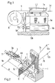
- a belt rapier weaving machine is shown with a sley 1 and a reed 2.
- the belt wheel 8 moves the rapier gripper head 3a, which is connected to the belt wheel 8 via the entry belt 9, back and forth in the shed.
- the slave gripper head 3d moving in the opposite direction to the carrier gripper head 3a takes over the weft thread in the middle of the fabric.
- the machine frame 10a, the floor 10b, the fabric 6a with a fabric edge 6e and a fabric width A, and the fabric tree 6b are also shown.
- FIG. 2 shows a sley 1, to which a reed 2 and two support elements 4, 5 for supporting the warp threads 7b of the lower shed are fastened.
- the shank eyelets 12a and 12b each determine the opening angle of the shed formed by the warp threads 7a and 7b.
- a bringer gripper head 3a is shown, which enters a weft thread 11 into the shed formed by the high-lying warp threads 7a and the low-lying warp threads 7b.
- the bringer gripper head 3a is shown slightly enlarged compared to the sley 1.
- the slave rapier head 3d which would approach the rapier rapier head 3a within the shed in the opposite direction, is not shown.
- the width of the fabric 6 is designated A.
- the bringer gripper head 3a with a width B in the warp thread direction lies on the deep warp threads 7b over its entire width B.
- the area AB is an area of the length A and the width B and denotes the area of the deep-lying warp threads 7b over which the two hook heads 3a, 3d slide or fly during the respective thread insertion.
- the two rapier heads 3a and 3d lie at the latest against the center of the fabric on the deep-lying warp threads 7b and slide into one another, whereupon the thread 11 is taken over by the slave rapier head 3d and then both rapier heads 3a and 3d predominantly on the warp threads 7b slidably pulled out of the shed through the entry tapes 9.
- No guide elements are provided for the rapier heads 3a and 3d within the shed, so that the direction of entry of the rapier heads 3a and 3d is mainly determined by the entry bands 9 which are stiff in the direction of the fabric stop.
- the position of the surface AB on the lower warp threads 7b is therefore mainly determined by the arrangement of the belt wheels 8 and entry belts 9, and always remains approximately at the same location at least in the direction of the fabric stop, whereas the deep-lying warp threads 7b move in the direction of the stop during the weaving process.
- the width B in the area of which the rapier heads 3a and 3d slide or fly over the warp threads, can also be greater than the effective width of a rapier head 3, since the entry belts 9 are subject to play in spite of their rigidity in the stop direction.
- This play of the rapier heads 3 in the warp thread direction causes the width B of the area AB swept by the rapier heads to be slightly larger than the effective width of the rapier heads 3.
- the support element 4 is adjoining the reed 2 and running parallel to it as a support rail for Supports the warp threads 7b.
- the second support element 5 is offset and fastened to the sley 1 parallel to the fabric stop edge 6c in such a way that the warp threads 7b of the lower shed are supported only outside the surface AB by the support rails 4 and 5.
- a rapier head 3 striking the warp threads 7b during thread insertion is resiliently damped by the warp threads 7b not supported in the area AB.
- the warp threads 7b are preferably deflected only in the elastic region, which means that a corresponding number of warp threads 7b with a corresponding tensile strength must be present in the sub-compartment.
- a correspondingly small number of supporting warp threads 7b is required in the lower compartment.
- a correspondingly large number of supporting warp threads 7b is required for fine fabrics.
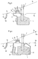
- Figure 3 shows a cross section through a similar arrangement.
- a fabric support rail 6d for supporting the fabric 6a in the area of the fabric stop edge 6c is shown as well as a fastening means 51 for attaching and adjusting the position of the warp thread support rail 5 on the sley 1.
- the gripper head 3 differs from the embodiment shown in FIG.
- a gripper head 3 with housing 3b and inner components 3c can be seen from the cross section.
- the housing 3b lies like a sled with 2 runners 3e on the warp threads 7b.
- An advantage of this type of gripper can be seen, for example, in the fact that the width B that passes over the warp threads 7b can be chosen wider than the actual gripper housing 3b.
- the gripper 3 thereby slides more stably over the warp threads 7b.
- the warp threads 7b rest on the warp thread support rails 4 and 5 during at least part of the thread entry and, coupled to the stop movement of the sley 1, lower in order to support the deep-lying warp threads 7b again during the subsequent thread insertion after a change of subject.
- the warp thread support rails 4 and 5 are shown in the present exemplary embodiment as separate elements. Of course, a U-shaped element whose two parallel legs have at least a distance B can also perform the same function as the two separate support rails 4 and 5.
- the support element 4 is fastened on the side facing the shaft eyelet 12b with a fastening device 42 on the sley 1.
- the support element 4 can also be firmly connected to the machine frame 10a in the position shown, so that only the support element 5 lying between the sley 1 and the fabric stop edge 6c coupled to the sley 1 carries out the stop movement in each case.
- FIG. 5 shows a U-shaped support element 4, the two warp thread support rails 4b of which run parallel to the direction of movement of the grippers on both sides outside the entry surface AB.
- the two warp thread support rails 4b are part of a single support element 4.
- the support element 4 has a connection between the warp thread support rails 4b, the surface 4a of the support element 4 facing the warp threads, for example, as one is formed flat surface which extends between the warp thread support rails 4b in the direction of movement of the hook.
- the two warp thread support rails 4b protrude the surface 4a by at least 1 mm, so that the surface 4a has no supporting function on the warp threads 7b of the deep pocket during the weft thread insertion.
- warp threads 7b and a gripper 3 which may be located above for example in partial areas of the surface AB lie on the surface 4a of the support element 4.
- openings such as bores, for example in the direction of gravity, such that the friction particles are removed via the openings.
- each of the support elements 4 or 5 can be arranged in such a way that they support the deep-lying warp threads 7b in the weft insertion position or also have a small distance, the distance can be in a range of up to one millimeter, so that the support elements 4 and / or 5 only have a supporting effect when the deflections are correspondingly larger.
- warp threads 7a, 7b and other supporting devices such as fabric support rail 6d or shaft eyelets 12b, it may also be sufficient to provide only one additional support element 4 or 5 for additional support of the warp threads 7b.
- the support elements 4 and 5 can in turn also have resilient or resilient properties and can be made of metallic materials or of plastics.
- the device according to the invention is always described in connection with a belt rapier weaving machine.
- the device according to the invention is also suitable for bar rapier weaving machines.
Landscapes
- Engineering & Computer Science (AREA)
- Textile Engineering (AREA)
- Looms (AREA)
Priority Applications (4)
| Application Number | Priority Date | Filing Date | Title |
|---|---|---|---|
| DE59207009T DE59207009D1 (de) | 1992-06-12 | 1992-06-12 | Greiferwebmaschine |
| EP92810455A EP0573727B1 (fr) | 1992-06-12 | 1992-06-12 | Métier à tisser à pinces |
| US08/055,124 US5345977A (en) | 1992-06-12 | 1993-04-29 | Gripper loom having warp thread bearer members |
| JP5141014A JPH0665839A (ja) | 1992-06-12 | 1993-06-11 | レピアテープグリッパ織機 |
Applications Claiming Priority (1)
| Application Number | Priority Date | Filing Date | Title |
|---|---|---|---|
| EP92810455A EP0573727B1 (fr) | 1992-06-12 | 1992-06-12 | Métier à tisser à pinces |
Publications (2)
| Publication Number | Publication Date |
|---|---|
| EP0573727A1 true EP0573727A1 (fr) | 1993-12-15 |
| EP0573727B1 EP0573727B1 (fr) | 1996-08-28 |
Family
ID=8211938
Family Applications (1)
| Application Number | Title | Priority Date | Filing Date |
|---|---|---|---|
| EP92810455A Expired - Lifetime EP0573727B1 (fr) | 1992-06-12 | 1992-06-12 | Métier à tisser à pinces |
Country Status (4)
| Country | Link |
|---|---|
| US (1) | US5345977A (fr) |
| EP (1) | EP0573727B1 (fr) |
| JP (1) | JPH0665839A (fr) |
| DE (1) | DE59207009D1 (fr) |
Families Citing this family (2)
| Publication number | Priority date | Publication date | Assignee | Title |
|---|---|---|---|---|
| ATE365241T1 (de) * | 2002-08-30 | 2007-07-15 | Promatech Spa | Verbesserungen an schussfadengreifern für webmaschinen und an webmaschinen mit führungsmitteln dafür |
| US20260002299A1 (en) * | 2024-06-30 | 2026-01-01 | Newbolt Ltd. | Freeform weaving loom |
Citations (4)
| Publication number | Priority date | Publication date | Assignee | Title |
|---|---|---|---|---|
| DE679808C (de) * | 1937-08-04 | 1939-08-16 | Sulzer Akt Ges Geb | Webstuhl mit Fuehrung fuer die Schussfadeneintragmittel |
| EP0352223A1 (fr) * | 1988-07-22 | 1990-01-24 | GebràDer Sulzer Aktiengesellschaft | Dispositif d'insertion de trame d'un métier à tisser à pinces |
| EP0446561A1 (fr) * | 1990-03-13 | 1991-09-18 | Sulzer RàTi Ag | Métier à tisser à pinces avec bandes d'insertion et éléments d'écartement pour les pinces |
| EP0468916A1 (fr) * | 1990-07-24 | 1992-01-29 | Sulzer RàTi Ag | Métier à tisser à griffes avec lamelles de guidage des griffes |
Family Cites Families (2)
| Publication number | Priority date | Publication date | Assignee | Title |
|---|---|---|---|---|
| IT1198246B (it) * | 1986-12-23 | 1988-12-21 | Vamatex Spa | Mezzi per guidare il moto di una coppia di pinze portatrama all'interno del passo di telai di tessitura |
| IT1227335B (it) * | 1988-09-08 | 1991-04-08 | Vamatex Spa | Mezzi per guidare il moto di pinze di alimentazione della trama all'interno del passo di telai di tessitura senza navette |
-
1992
- 1992-06-12 DE DE59207009T patent/DE59207009D1/de not_active Expired - Fee Related
- 1992-06-12 EP EP92810455A patent/EP0573727B1/fr not_active Expired - Lifetime
-
1993
- 1993-04-29 US US08/055,124 patent/US5345977A/en not_active Expired - Fee Related
- 1993-06-11 JP JP5141014A patent/JPH0665839A/ja active Pending
Patent Citations (4)
| Publication number | Priority date | Publication date | Assignee | Title |
|---|---|---|---|---|
| DE679808C (de) * | 1937-08-04 | 1939-08-16 | Sulzer Akt Ges Geb | Webstuhl mit Fuehrung fuer die Schussfadeneintragmittel |
| EP0352223A1 (fr) * | 1988-07-22 | 1990-01-24 | GebràDer Sulzer Aktiengesellschaft | Dispositif d'insertion de trame d'un métier à tisser à pinces |
| EP0446561A1 (fr) * | 1990-03-13 | 1991-09-18 | Sulzer RàTi Ag | Métier à tisser à pinces avec bandes d'insertion et éléments d'écartement pour les pinces |
| EP0468916A1 (fr) * | 1990-07-24 | 1992-01-29 | Sulzer RàTi Ag | Métier à tisser à griffes avec lamelles de guidage des griffes |
Also Published As
| Publication number | Publication date |
|---|---|
| JPH0665839A (ja) | 1994-03-08 |
| DE59207009D1 (de) | 1996-10-02 |
| EP0573727B1 (fr) | 1996-08-28 |
| US5345977A (en) | 1994-09-13 |
Similar Documents
| Publication | Publication Date | Title |
|---|---|---|
| CH477579A (de) | Fussbodenbelagmaterial aus Florgewebe | |
| DD269408A5 (de) | Fuehrungsmittel zur bewegung eines mit greifern versehenen schusspaares innerhalb des webfaches eines webstuhles | |
| CH617232A5 (fr) | ||
| DE3781707T2 (de) | Verfahren und vorrichtung zum klemmen, festhalten und vorfuehren von schussfaeden bei greiferwebmaschinen. | |
| DE3032929C2 (fr) | ||
| EP0468916A1 (fr) | Métier à tisser à griffes avec lamelles de guidage des griffes | |
| EP0573727B1 (fr) | Métier à tisser à pinces | |
| DE60318265T3 (de) | Grundgewebe für Papiermacherpressfilz und Papiermacherpressfilz | |
| EP0446424B1 (fr) | Métier à tisser à griffes pour tissus lourds | |
| EP0446561B1 (fr) | Métier à tisser à pinces avec bandes d'insertion et éléments d'écartement pour les pinces | |
| DE3421638C2 (de) | Webblatt mit integriertem Eintragkanal für eine schützenlose Webmaschine mit pneumatischem Schußfadeneintrag | |
| CH625573A5 (en) | Taker gripper for weaving machines with extraction of the weft thread from fixed bobbins | |
| DD225863A3 (de) | Schussfadeneintragsvorrichtung | |
| DE60220788T2 (de) | Verbesserungen an Schussfadengreifern für Webmaschinen und an Webmaschinen mit Führungsmitteln dafür | |
| EP0352411B1 (fr) | Griffe avec pièce de guidage pour métiers à tisser | |
| DE102005028124A1 (de) | Frottierwebmaschine | |
| DE2947399A1 (de) | Vorrichtung an schuetzenlosen webmaschinen zur uebergabe der schussfadenspitze | |
| EP0597493B1 (fr) | Métier à tisser les jointures pour lier un tissu synthétique avec une machine Jacquard placée en dessous de la foule | |
| EP0741200A1 (fr) | Dispositif à griffes pour un métier à tisser à griffes | |
| DE2558395A1 (de) | Antriebsmechanismus fuer in schuetzenlosen webmaschinen verwendete stricknadeln zum bilden einer warenleiste | |
| DE19537867A1 (de) | Schußfadenschneidvorrichtung für Webmaschinen, insbesondere Doppelteppichwebmaschinen | |
| EP1405943B1 (fr) | Métier pour la fabrication de tissus de gaze | |
| DE1535292C3 (de) | Greiferwebstuhl fur Doppelgewebe | |
| DE68906622T2 (de) | Schussfadengreiferpaar mit auswechselbarer Abfütterung. | |
| DE19838476A1 (de) | Greiferbandwebmaschine mit wenigstens einem Greiferband und Führungsmitteln |
Legal Events
| Date | Code | Title | Description |
|---|---|---|---|
| PUAI | Public reference made under article 153(3) epc to a published international application that has entered the european phase |
Free format text: ORIGINAL CODE: 0009012 |
|
| AK | Designated contracting states |
Kind code of ref document: A1 Designated state(s): BE DE FR IT |
|
| RAP1 | Party data changed (applicant data changed or rights of an application transferred) |
Owner name: SULZER RUETI AG |
|
| 17P | Request for examination filed |
Effective date: 19940504 |
|
| 17Q | First examination report despatched |
Effective date: 19950529 |
|
| GRAH | Despatch of communication of intention to grant a patent |
Free format text: ORIGINAL CODE: EPIDOS IGRA |
|
| GRAH | Despatch of communication of intention to grant a patent |
Free format text: ORIGINAL CODE: EPIDOS IGRA |
|
| GRAA | (expected) grant |
Free format text: ORIGINAL CODE: 0009210 |
|
| AK | Designated contracting states |
Kind code of ref document: B1 Designated state(s): BE DE FR IT |
|
| PG25 | Lapsed in a contracting state [announced via postgrant information from national office to epo] |
Ref country code: FR Effective date: 19960828 |
|
| REF | Corresponds to: |
Ref document number: 59207009 Country of ref document: DE Date of ref document: 19961002 |
|
| ITF | It: translation for a ep patent filed | ||
| EN | Fr: translation not filed | ||
| PG25 | Lapsed in a contracting state [announced via postgrant information from national office to epo] |
Ref country code: BE Effective date: 19970630 |
|
| PLBE | No opposition filed within time limit |
Free format text: ORIGINAL CODE: 0009261 |
|
| 26N | No opposition filed | ||
| BERE | Be: lapsed |
Owner name: SULZER RUTI A.G. Effective date: 19970630 |
|
| PGFP | Annual fee paid to national office [announced via postgrant information from national office to epo] |
Ref country code: DE Payment date: 20040604 Year of fee payment: 13 |
|
| PG25 | Lapsed in a contracting state [announced via postgrant information from national office to epo] |
Ref country code: IT Free format text: LAPSE BECAUSE OF NON-PAYMENT OF DUE FEES Effective date: 20050612 |
|
| PG25 | Lapsed in a contracting state [announced via postgrant information from national office to epo] |
Ref country code: DE Free format text: LAPSE BECAUSE OF NON-PAYMENT OF DUE FEES Effective date: 20060103 |