EP0573961A2 - Thermoelektrisches Material und dieses Material anwendender Sensor - Google Patents
Thermoelektrisches Material und dieses Material anwendender Sensor Download PDFInfo
- Publication number
- EP0573961A2 EP0573961A2 EP93109206A EP93109206A EP0573961A2 EP 0573961 A2 EP0573961 A2 EP 0573961A2 EP 93109206 A EP93109206 A EP 93109206A EP 93109206 A EP93109206 A EP 93109206A EP 0573961 A2 EP0573961 A2 EP 0573961A2
- Authority
- EP
- European Patent Office
- Prior art keywords
- thermoelectric
- sensor
- thermoelectric material
- temperature difference
- fine particles
- Prior art date
- Legal status (The legal status is an assumption and is not a legal conclusion. Google has not performed a legal analysis and makes no representation as to the accuracy of the status listed.)
- Granted
Links
Images



Classifications
-
- G—PHYSICS
- G01—MEASURING; TESTING
- G01N—INVESTIGATING OR ANALYSING MATERIALS BY DETERMINING THEIR CHEMICAL OR PHYSICAL PROPERTIES
- G01N25/00—Investigating or analyzing materials by the use of thermal means
- G01N25/20—Investigating or analyzing materials by the use of thermal means by investigating the development of heat, i.e. calorimetry, e.g. by measuring specific heat, by measuring thermal conductivity
- G01N25/22—Investigating or analyzing materials by the use of thermal means by investigating the development of heat, i.e. calorimetry, e.g. by measuring specific heat, by measuring thermal conductivity on combustion or catalytic oxidation, e.g. of components of gas mixtures
- G01N25/28—Investigating or analyzing materials by the use of thermal means by investigating the development of heat, i.e. calorimetry, e.g. by measuring specific heat, by measuring thermal conductivity on combustion or catalytic oxidation, e.g. of components of gas mixtures the rise in temperature of the gases resulting from combustion being measured directly
- G01N25/30—Investigating or analyzing materials by the use of thermal means by investigating the development of heat, i.e. calorimetry, e.g. by measuring specific heat, by measuring thermal conductivity on combustion or catalytic oxidation, e.g. of components of gas mixtures the rise in temperature of the gases resulting from combustion being measured directly using electric temperature-responsive elements
- G01N25/32—Investigating or analyzing materials by the use of thermal means by investigating the development of heat, i.e. calorimetry, e.g. by measuring specific heat, by measuring thermal conductivity on combustion or catalytic oxidation, e.g. of components of gas mixtures the rise in temperature of the gases resulting from combustion being measured directly using electric temperature-responsive elements using thermoelectric elements
-
- H—ELECTRICITY
- H10—SEMICONDUCTOR DEVICES; ELECTRIC SOLID-STATE DEVICES NOT OTHERWISE PROVIDED FOR
- H10N—ELECTRIC SOLID-STATE DEVICES NOT OTHERWISE PROVIDED FOR
- H10N10/00—Thermoelectric devices comprising a junction of dissimilar materials, i.e. devices exhibiting Seebeck or Peltier effects
- H10N10/10—Thermoelectric devices comprising a junction of dissimilar materials, i.e. devices exhibiting Seebeck or Peltier effects operating with only the Peltier or Seebeck effects
- H10N10/17—Thermoelectric devices comprising a junction of dissimilar materials, i.e. devices exhibiting Seebeck or Peltier effects operating with only the Peltier or Seebeck effects characterised by the structure or configuration of the cell or thermocouple forming the device
-
- G—PHYSICS
- G01—MEASURING; TESTING
- G01N—INVESTIGATING OR ANALYSING MATERIALS BY DETERMINING THEIR CHEMICAL OR PHYSICAL PROPERTIES
- G01N27/00—Investigating or analysing materials by the use of electric, electrochemical, or magnetic means
- G01N27/002—Investigating or analysing materials by the use of electric, electrochemical, or magnetic means by investigating the work function voltage
-
- H—ELECTRICITY
- H10—SEMICONDUCTOR DEVICES; ELECTRIC SOLID-STATE DEVICES NOT OTHERWISE PROVIDED FOR
- H10N—ELECTRIC SOLID-STATE DEVICES NOT OTHERWISE PROVIDED FOR
- H10N10/00—Thermoelectric devices comprising a junction of dissimilar materials, i.e. devices exhibiting Seebeck or Peltier effects
- H10N10/01—Manufacture or treatment
-
- H—ELECTRICITY
- H10—SEMICONDUCTOR DEVICES; ELECTRIC SOLID-STATE DEVICES NOT OTHERWISE PROVIDED FOR
- H10N—ELECTRIC SOLID-STATE DEVICES NOT OTHERWISE PROVIDED FOR
- H10N10/00—Thermoelectric devices comprising a junction of dissimilar materials, i.e. devices exhibiting Seebeck or Peltier effects
- H10N10/80—Constructional details
- H10N10/85—Thermoelectric active materials
- H10N10/851—Thermoelectric active materials comprising inorganic compositions
- H10N10/852—Thermoelectric active materials comprising inorganic compositions comprising tellurium, selenium or sulfur
-
- H—ELECTRICITY
- H10—SEMICONDUCTOR DEVICES; ELECTRIC SOLID-STATE DEVICES NOT OTHERWISE PROVIDED FOR
- H10N—ELECTRIC SOLID-STATE DEVICES NOT OTHERWISE PROVIDED FOR
- H10N10/00—Thermoelectric devices comprising a junction of dissimilar materials, i.e. devices exhibiting Seebeck or Peltier effects
- H10N10/80—Constructional details
- H10N10/85—Thermoelectric active materials
- H10N10/851—Thermoelectric active materials comprising inorganic compositions
- H10N10/8556—Thermoelectric active materials comprising inorganic compositions comprising compounds containing germanium or silicon
-
- Y—GENERAL TAGGING OF NEW TECHNOLOGICAL DEVELOPMENTS; GENERAL TAGGING OF CROSS-SECTIONAL TECHNOLOGIES SPANNING OVER SEVERAL SECTIONS OF THE IPC; TECHNICAL SUBJECTS COVERED BY FORMER USPC CROSS-REFERENCE ART COLLECTIONS [XRACs] AND DIGESTS
- Y10—TECHNICAL SUBJECTS COVERED BY FORMER USPC
- Y10T—TECHNICAL SUBJECTS COVERED BY FORMER US CLASSIFICATION
- Y10T428/00—Stock material or miscellaneous articles
- Y10T428/12—All metal or with adjacent metals
- Y10T428/12014—All metal or with adjacent metals having metal particles
- Y10T428/12028—Composite; i.e., plural, adjacent, spatially distinct metal components [e.g., layers, etc.]
- Y10T428/12042—Porous component
Definitions
- the present invention relates to an improvement of a thermoelectric material useful for power generation, refrigeration, and the like, and also to a sensor using the thermoelectric material. More specifically, the invention relates to a thermoelectric material using a material having Seebeck effect and a sensor using the same thermoelectric material, and to a method of manufacturing the same.
- the Seebeck effect is a phenomenon that, when a temperature difference arises between two different points of an electrically conductive material, an electromotive force is developed in proportion to the temperature difference.
- the electromotive force consists of two components, i.e., an electromotive force due to distribution of charge carrier density caused by a migration of charge carriers for keeping constant free energy of the charge carriers within the material, and another electromotive force due to an interaction between charge carriers and heat flow, namely, phonon flow from higher- to lower-temperature portions.
- thermoelectric effects of the material such as thermal electromotive force (i.e., Seebeck electromotive force) are different between its surface portion and internal portion.
- thermal electromotive force i.e., Seebeck electromotive force
- the surface portion occupies larger part relative to the internal portion so that the thermoelectric effect in the surface portion can no longer be an ignorable phenomenon.
- thermoelectric material has atmospheric gasses such as oxygen, nitrogen, steam, carbon dioxide and the like adsorbed thereon, which, it is considered, would affect the thermoelectric effects on the surface portion (interface portion).
- atmospheric gasses such as oxygen, nitrogen, steam, carbon dioxide and the like adsorbed thereon, which, it is considered, would affect the thermoelectric effects on the surface portion (interface portion).
- an adsorption amount of atmospheric gas increases with increasing the pressure of the atmospheric gas so that the higher the pressure of the atmospheric gas, the greater the change in the thermal electromotive force.
- thermoelectric materials capable of interconversion between temperature difference and electromotive force have been manufactured heretofore, as bulk materials, by melt-casting a thermoelectric material or calcining a powdery material at a high temperature, and their resulting fine structures are shown in Figs. 7 and 8, respectively.
- thermoelectric materials in the conventional material prepared by melt-casting a thermoelectric material, crystal grains are arranged densely and continuously although a small amount of cracks 13 and pores 14 may exist as shown in Fig. 7.
- the particles are partly fused and electrically linked to each other as shown by reference numeral 15 in Fig. 8.
- thermoelectric materials formed through deposition on a glass substrate or organic membrane or other methods. In either case of the conventional methods, thermoelectric materials have been provided in a structure as dense as possible so that their electrical conductivity and mechanical strength as a bulk material would be enhanced for increased practicability.
- thermoelectric materials are in most cases implemented by making use of a function of detecting temperature difference.
- sensors include temperature sensors or electric thermometers incorporating alloy thermocouples such as iron/gold - chromel and alumel - chromel thermocouples.
- alloy thermocouples such as iron/gold - chromel and alumel - chromel thermocouples.
- An example of the sensors can be found in an application for detecting an extinction of a pilot burner of a boiler by sensing a change in temperature difference.
- thermoelectric phenomenon has been applied.
- thermoelectric materials have been used as materials for converting temperature difference into electricity due to thermal electromotive force or obtaining temperature difference by conducting an electric current through the materials.
- sensors using these materials which have been applied only for detecting temperature difference, there is a difficulty in measuring other physical quantities such as gas pressure, concentration of a substance in a solution.
- an essential objective of the present invention is to provide an improvement of performance of thermoelectric materials and to provide a method of manufacturing a sensor using the thermoelectric material having Seebeck effect, allowing the sensor capable to detect a gas pressure and concentration of specific substances quantitatively.
- thermoelectric material comprises a structure such that fine particles of a material exhibiting Seebeck effect are electrically linked partially in a loose-contact state one another.
- loose-contact state means a semipressure-contact state of fine particles to be electrically linked without fusing, having spaces formed at clearances between any adjacent fine particles when formed in a cold pressing or sintering process.
- thermoelectric materials according to the present invention comprises a step of compacting fine particles exhibiting Seebeck effect through a cold press forming.
- a sensor for measuring gas pressures comprises: a piece of a thermoelectric material in which fine particles exhibiting Seebeck effect are electrically linked in a loose-contact state one another with spaces formed at clearances between adjacent fine particles; means for giving temperature difference between two points inside the piece of the thermoelectric material; and means for detecting thermal electromotive force generated between the two points in the material.
- a sensor for detecting a specific substance comprises: a piece of thermoelectric material in which fine particles exhibiting Seebeck effect are electrically linked in a loose-contact state one another, the piece of the theromoelectric material being combined with a material having a specificity of adsorption or reaction, having spaces formed at clearances between adjacent fine particles; means for giving temperature difference between two points inside the piece of the thermoelectric material; and means for detecting a thermal electromotive force generated between the two points.
- a material having adsorption specificity or reaction specificity is preferably formed in a film-like state mainly on the surface of the particles of thermoelectric material.
- gas pressure and concentration of a specific substance can be detected correctly in a form of voltage using a thermoelectric material in which fine particles of a material exhibiting Seebeck effect are electrically linked in a loose-contact state one another with spaces formed at clearances between adjacent fine particles.
- thermoelectric material mentioned above can be manufactured efficiently and rationally.
- the arrangement of the sensor for measuring a gas pressure detects a change in the thermal electromotive force when the gas pressure of the atmosphere is varied, thereby to measure an atmospheric gas pressure.
- a concentration of a specific substance in a solution or an atmosphere can be detected.
- thermoelectric materials for use in sensors are so constructed that fine particles of thermoelectric materials are electrically linked partially in a loose-contact state one another, high sensitivities of the sensors can be enhanced.
- the amount of adsorbed atmospheric gas increases with increasing the pressure of the atmospheric gas. Therefore, the higher the pressure of the atmospheric gas, the greater the change in the thermoelectric force. Further, when the thermoelectric material is combined with various types of materials having a specificity of adsorption or reaction, adsorption of a specific substance onto the material will cause a change in the thermal electromotive force generated in the material.
- thermoelectric material according to the present invention is more strongly affected by the adsorbed gas since charge carriers and phonons traverse the adsorption layer.
- thermoelectric material a method of producing a thermoelectric material will be explained below.
- specified amounts of raw materials of Fe, Mn and Si each having purity of not less than 3N (> 99.9%) were melted in an arc furnace and then crushed.
- Fe and Si are used as basic materials while Mn is used as a doping material.
- the composition of the resultant material was analyzed and the ratio of the raw materials was adjusted to derive a composition of Fe 0.985 Mn 0.015 Si2.
- the material having a composition of Fe 0.985 Mn 0.015 Si2 was put into a vacuum sealed glass ample and annealed at 850 °C for eight hours in the glass ample. Then the annealed material was milled in a planetary ball mill for five minutes under an Ar gas atmosphere, and shifted through a mesh to obtain a powder material consisting of particles each having a size of about 5 ⁇ m in diameter.
- the powder material was molded by cold pressing under a pressure in a range of 1000 to 3000 kgw/cm2 at a room temperature so that the powder material was pelletized.
- a small amount of ethanol or acetone was added to the powder to enhance the rigidity of the pellets. That is, ethanol or acetone serves as a lubricant to remove cracks or the like in the pellets.
- Seebeck coefficients for the pellets of the resultant material were measured under various pressures of atmospheric gas.
- Mn was used as a doping material
- other materials such as Co, Cr and Al may be used as a doping material.
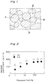
- Fig. 1 shows a fine structure of the thermoelectric material obtained by the above mentioned processes.
- Each particle of the thermoelectric material having a composition of Fe 0.985 Mn 0.015 Si2 coheres together in a loose-contact state without fusing so that atmospheric gas can be adsorbed onto a surface 3 and fed to be adsorbed to a loose-contact part 4 through a cavity 2. That is, substantially no solid or liquid material exists in the cavity 2.
- thermoelectric material Seebeck coefficients of the pellets of the thermoelectric material were measured in a container in which the conditions of atmospheric gas (i.e., pressure, species of the gas) can be adjusted.
- atmospheric gas i.e., pressure, species of the gas
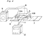
- Fig. 2 shows a distribution of Seebeck coefficients depending on the atmospheric gas pressure when measured under Ar and He gaseous atmospheres. Seebeck coefficient was found to largely depend upon the pressure of atmospheric gas, particularly in a range of the pressure below 100 mmHg. Also, Seebeck coefficient was found to be different between species of He and Ar gaseous atmospheres even at the same pressure. Therefore, the thermoelectric material appears to have a function of identifying species of atmospheric gas to some degree.
- the influence of the pressure of atmospheric gas on Seebeck coefficient was also investigated for a basic material of Bi2Te3 except for a material of Fe-Si group.
- the Bi2Te3 material having purity of not less than 3N (i.e., > 99.9%) was crushed and then shifted through a mesh to obtain a powder material composed of particles each having a size of about 10 ⁇ m in diameter.
- the powder material was pelletized under a pressure of 500 to 2000 kgw/cm2. Then Seebeck coefficients for the pellets of the resultant material were measured under various pressures of atmospheric gas.
- Fig. 3 shows a distribution of Seebeck coefficients depending on the atmospheric gas pressure when measured under Ar gaseous atmosphere. Seebeck coefficient was found to depend upon the pressure of atmospheric gas, particularly in a range of the pressure below 100 mmHg. It was found that Seebeck coefficients for the material of Bi2Te3 depend upon the pressure of atmospheric gas although the degree of the dependency was not so high as that of the Fe-Si group materials.
- a pellet 5 is provided with a rectangular shaped plate having dimensions of 2 mm x 2 mm x 10 mm, which is made of the thermoelectric material having a composition of Fe 0.985 Mn 0.015 Si2.
- a heater 6 is mounted to one end of the pellet 5 for heating, while a cooling plate 7 serving as a heat sink is attached to the other end of the pellet 5 for discharging heat.
- thermocouples 8 Electric current is applied from a power source (not shown) to the heater 6 for heating through a controller 9.
- the applied electric current is controlled by the controller 9 in such a manner that the temperature difference between the both ends of the pellet 5 is kept constant at a difference value of 10°C by providing thermocouples 8.
- each of the thermocouples 8 is connected to the heater plate 6 and the cooling plate 7, where the controller 9 is electrically connected in the loop circuit of the thermocouples 8 to control the heating of the heater 6 by detecting thermoelectric current corresponding to the temperature difference.
- a pair of electrodes 10A and 10B, each of which is made of silver paste, are provided in the both end portions of the pellet 5 for measuring thermal electromotive force developed in the pellet 5, where the electrode 10A is positioned in the left side in the figure corresponding to the heater plate 6 while the electrode 10B is positioned in the right side in the figure corresponding to the cooling plate 7 as shown in Fig. 4.
- the voltage due to the thermal electromotive force in accordance with the temperature difference is measured by means of a voltmeter 12 which is electrically connected across the both electrodes 10A and 10B via silver lead wires 11.
- Ar gas was introduced into a chamber or container and it was repeatedly confirmed that the Seebeck coefficients correspond to the gas pressures in a one-by-one manner.
- a powder thermoelectric material having a composition of Fe 0.985 Mn 0.015 Si2 was previously obtained by the production method as described before, which the material was processed into granules each having a size of 5 to 10 ⁇ m in diameter. Then, in order to obtain a material having a specificity of adsorption or reaction, formaldehyde dehydrogenase enzyme was mixed into polyacrylamide sol and further mixed with the above processed powder thermoelectric material of Fe 0.985 Mn 0.015 Si2, thereby to obtain a slurry state, where the polyacrylamide sol is used as a supporting member. The mixed slurry material was atomized in a dried Ar gas atmosphere so that the polyacrylamide sol was geratinizated and then excessive solvent was dispersed by evaporation.
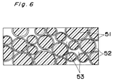
- the particles 51 of the powder material of Fe 0.985 Mn 0.015 Si2 were coated with a thin-film like polyacrylamide gel 52 including enzyme.
- spaces 53 i.e., cavities among the particles.
- the obtained powder material was dispersed in an organic solvent and formed on a glass substrate through a printing method.
- a temperature difference of 10°C was kept constant and the variation in thermal electromotive force was traced.
- the measurement values of electromotive force for atmospheres of Ar gas containing formaldehyde of 1 ppm, 10 ppm and 100 ppm were respectively 2350 ⁇ V, 2550 ⁇ V and 2700 ⁇ V, which were increased by 300 ⁇ V, 500 ⁇ V and 650 ⁇ V respectively comparing to the value (2050 ⁇ V) for pure Ar gas.
- the foregoing example is an application of enzyme reaction for sensing a concentration of a specific substance in a gas atmosphere.
- concentration of a specific substance in a solution can also be detected and a wide variety of detectable substances can be selected.
- thermoelectric particles As a method for supporting these materials having adsorption specificities, there can be used a cellulose membrane. Another method can be also adopted by fixing antibodies or enzymes directly on the surface of fine thermoelectric particles through a chemical reaction. On the other hand, although the sensitivity was not very high, gas pressures and concentrations of specific substances could be detected by using a thin film of approximately 1 ⁇ m thick instead of fine thermoelectric particles.
- the material has a fine structure in cross section in which fine particles 1 cohere together in a loose-contact state without fusing and an adsorption of atmospheric gas or that of specific substance through an enzyme reaction occurs on the surface 3 and the loose-contact part 4 through the cavity 2 as shown in Fig. 1.
- the thermal electromotive force changes depending upon the amount of adsorption and then the system acts as a sensor. Accordingly, a gas pressure and a concentration of a specific substance can be detected in a form of a voltage by using thermoelectric materials.
- thermoelectric material of the present invention As described above, according to the present invention, gas pressures and concentrations of specific substances can be detected correctly in a form of voltage by using a thermoelectric material of the present invention by virtue of the structure that fine particles of a material exhibiting the Seebeck effect are electrically linked in a loose-contact state while spaces are formed at clearances among the particles.
- the sensor of the present invention is very profitable in the industry since gas pressures or concentrations of specific substances can be detected as voltage values.
Landscapes
- Chemical & Material Sciences (AREA)
- Inorganic Chemistry (AREA)
- Engineering & Computer Science (AREA)
- Biochemistry (AREA)
- General Physics & Mathematics (AREA)
- Health & Medical Sciences (AREA)
- Life Sciences & Earth Sciences (AREA)
- Analytical Chemistry (AREA)
- Combustion & Propulsion (AREA)
- General Health & Medical Sciences (AREA)
- Physics & Mathematics (AREA)
- Immunology (AREA)
- Pathology (AREA)
- Chemical Kinetics & Catalysis (AREA)
- Manufacturing & Machinery (AREA)
- Electrochemistry (AREA)
- Measuring Temperature Or Quantity Of Heat (AREA)
- Investigating Or Analyzing Materials Using Thermal Means (AREA)
Applications Claiming Priority (2)
| Application Number | Priority Date | Filing Date | Title |
|---|---|---|---|
| JP149298/92 | 1992-06-09 | ||
| JP4149298A JPH05343747A (ja) | 1992-06-09 | 1992-06-09 | 熱電材料及びその製造方法並びにセンサー |
Publications (3)
| Publication Number | Publication Date |
|---|---|
| EP0573961A2 true EP0573961A2 (de) | 1993-12-15 |
| EP0573961A3 EP0573961A3 (de) | 1994-03-23 |
| EP0573961B1 EP0573961B1 (de) | 1997-11-19 |
Family
ID=15472110
Family Applications (1)
| Application Number | Title | Priority Date | Filing Date |
|---|---|---|---|
| EP93109206A Expired - Lifetime EP0573961B1 (de) | 1992-06-09 | 1993-06-08 | Thermoelektrisches Material und dieses Material anwendender Sensor |
Country Status (4)
| Country | Link |
|---|---|
| US (1) | US5507879A (de) |
| EP (1) | EP0573961B1 (de) |
| JP (1) | JPH05343747A (de) |
| DE (1) | DE69315260T2 (de) |
Cited By (1)
| Publication number | Priority date | Publication date | Assignee | Title |
|---|---|---|---|---|
| EP1550860A1 (de) * | 2003-12-26 | 2005-07-06 | Alps Electric Co., Ltd. | Wasserstoffsensor, Vorrichtung zur Wasserstoffkonzentrationsmessung und Verfahren zur Wasserstoffkonzentrationsmessung |
Families Citing this family (13)
| Publication number | Priority date | Publication date | Assignee | Title |
|---|---|---|---|---|
| US6232542B1 (en) * | 1996-11-15 | 2001-05-15 | Citizen Watch Co., Ltd. | Method of fabricating thermoelectric device |
| JPH1132492A (ja) * | 1997-05-14 | 1999-02-02 | Nissan Motor Co Ltd | 熱電発電装置及びその駆動方法 |
| US6127619A (en) * | 1998-06-08 | 2000-10-03 | Ormet Corporation | Process for producing high performance thermoelectric modules |
| DE10030354A1 (de) * | 2000-06-21 | 2002-01-10 | Bosch Gmbh Robert | Thermoelektrisches Bauelement |
| EP1293769A3 (de) * | 2001-09-07 | 2004-11-03 | National Institute of Advanced Industrial Science and Technology | Sensor für entflammbare Gase , Verfahren und Vorrichtung zur Messung von Gaskonzentrationen |
| US7340304B2 (en) * | 2002-03-15 | 2008-03-04 | Biomed Soutions, Llc | Biothermal power source for implantable devices |
| US20040093041A1 (en) * | 2002-03-15 | 2004-05-13 | Macdonald Stuart G. | Biothermal power source for implantable devices |
| CN102053100B (zh) * | 2010-12-06 | 2013-01-09 | 中山大学 | 热电材料参数自动测定仪 |
| KR101713281B1 (ko) * | 2010-12-17 | 2017-03-07 | 삼성전자주식회사 | 코팅층 함유 열전재료, 그의 제조방법과 이를 포함하는 열전장치 |
| US8779276B2 (en) * | 2011-07-14 | 2014-07-15 | Sony Corporation | Thermoelectric device |
| US10197519B2 (en) | 2013-03-15 | 2019-02-05 | H2Scan Corporation | Gas sensing systems and methods |
| US10014364B1 (en) | 2017-03-16 | 2018-07-03 | Globalfoundries Inc. | On-chip resistors with a tunable temperature coefficient of resistance |
| US11815444B2 (en) * | 2021-10-14 | 2023-11-14 | Saudi Arabian Oil Company | Thermoelectric polymer system for corrosion monitoring |
Family Cites Families (23)
| Publication number | Priority date | Publication date | Assignee | Title |
|---|---|---|---|---|
| GB578187A (en) * | 1941-07-02 | 1946-06-19 | Ernst Schwarz | Improvements in or relating to thermo-electric devices |
| US3182391A (en) * | 1960-02-29 | 1965-05-11 | Westinghouse Electric Corp | Process of preparing thermoelectric elements |
| US3082277A (en) * | 1960-04-19 | 1963-03-19 | Westinghouse Electric Corp | Thermoelectric elements |
| US3201504A (en) * | 1961-10-16 | 1965-08-17 | Carrler Corp | Method of making a thermo-electric couple |
| US3164892A (en) * | 1962-11-27 | 1965-01-12 | Gen Instrument Corp | Thermoelectric body and method of making same |
| US3906721A (en) * | 1974-08-22 | 1975-09-23 | Gen Motors Corp | Thermoelectric exhaust gas sensor |
| US4029472A (en) * | 1976-04-05 | 1977-06-14 | General Motors Corporation | Thermoelectric exhaust gas sensor |
| US4141955A (en) * | 1977-10-25 | 1979-02-27 | Obiaya Joseph O | Combustible concentration analyzer |
| US4588520A (en) * | 1982-09-03 | 1986-05-13 | Energy Conversion Devices, Inc. | Powder pressed thermoelectric materials and method of making same |
| JPS59145582A (ja) * | 1983-02-09 | 1984-08-21 | Futaba Corp | 鉄けい化物熱電変換素子 |
| US4465895A (en) * | 1983-06-01 | 1984-08-14 | Ecd-Anr Energy Conversion Company | Thermoelectric devices having improved elements and element interconnects and method of making same |
| JPS60158346A (ja) * | 1984-01-30 | 1985-08-19 | Ngk Spark Plug Co Ltd | ガスセンサ |
| US4589918A (en) * | 1984-03-28 | 1986-05-20 | National Research Institute For Metals | Thermal shock resistant thermoelectric material |
| US4717788A (en) * | 1984-12-06 | 1988-01-05 | General Electric Company | Method for producing thermoelectric elements |
| JP2556970B2 (ja) * | 1986-07-30 | 1996-11-27 | 株式会社小松製作所 | 熱電材料の製造方法 |
| US4764212A (en) * | 1986-02-21 | 1988-08-16 | Kabushiki Kaisha Komatsu Seisakusho | Thermoelectric material for low temperature use and method of manufacturing the same |
| EP0335213A3 (de) * | 1988-03-30 | 1990-01-24 | Idemitsu Petrochemical Co. Ltd. | Verfahren zur Herstellung thermoelektrischer Elemente |
| GB2222908A (en) * | 1988-09-14 | 1990-03-21 | Haroon Ahmed | Sensor device |
| JPH038707A (ja) * | 1989-06-02 | 1991-01-16 | Mitsubishi Materials Corp | n型Fe珪化物熱電変換材料 |
| JPH0374885A (ja) * | 1989-08-15 | 1991-03-29 | Mitsubishi Materials Corp | P型Fe珪化物熱電変換材料 |
| JPH03148879A (ja) * | 1989-11-06 | 1991-06-25 | Matsushita Electric Ind Co Ltd | 熱電素子 |
| DE69132779T2 (de) * | 1990-04-20 | 2002-07-11 | Matsushita Electric Industrial Co., Ltd. | Vakuumisolierter thermoelektrischer Halbleiter und thermoelektrisches Bauelement, das P- und N-Typ thermoelektrische Halbleiter benutzt |
| EP0522182A1 (de) * | 1991-01-30 | 1993-01-13 | Idemitsu Petrochemical Co. Ltd. | Verfahren zur herstellung thermoelektrischer elemente |
-
1992
- 1992-06-09 JP JP4149298A patent/JPH05343747A/ja active Pending
-
1993
- 1993-06-08 DE DE69315260T patent/DE69315260T2/de not_active Expired - Fee Related
- 1993-06-08 US US08/072,940 patent/US5507879A/en not_active Expired - Fee Related
- 1993-06-08 EP EP93109206A patent/EP0573961B1/de not_active Expired - Lifetime
Cited By (2)
| Publication number | Priority date | Publication date | Assignee | Title |
|---|---|---|---|---|
| EP1550860A1 (de) * | 2003-12-26 | 2005-07-06 | Alps Electric Co., Ltd. | Wasserstoffsensor, Vorrichtung zur Wasserstoffkonzentrationsmessung und Verfahren zur Wasserstoffkonzentrationsmessung |
| US7174768B2 (en) | 2003-12-26 | 2007-02-13 | Alps Electric Co., Ltd. | Hydrogen sensor, apparatus for measuring hydrogen concentration, and method for measuring hydrogen concentration |
Also Published As
| Publication number | Publication date |
|---|---|
| US5507879A (en) | 1996-04-16 |
| DE69315260D1 (de) | 1998-01-02 |
| DE69315260T2 (de) | 1998-03-12 |
| EP0573961A3 (de) | 1994-03-23 |
| EP0573961B1 (de) | 1997-11-19 |
| JPH05343747A (ja) | 1993-12-24 |
Similar Documents
| Publication | Publication Date | Title |
|---|---|---|
| US5507879A (en) | Sensor utilizing thermoelectric material and method for manufacture thereof | |
| Mutschall et al. | Sputtered molybdenum oxide thin films for NH3 detection | |
| Sberveglieri et al. | Methods for the preparation of NO, NO2 and H2 sensors based on tin oxide thin films, grown by means of the rf magnetron sputtering technique | |
| CA1221735A (en) | Semiconductor oxide gas combustibles sensor | |
| Chung et al. | Tin oxide microsensor for LPG monitoring | |
| US4835059A (en) | Thin film conductor which contains silicon and germanium as major components and method of manufacturing the same | |
| Chakraborty et al. | Direct current conductivity and oxygen gas-sensing properties of iron–antimony–tellurite glasses | |
| Lampe et al. | Thin-film oxygen sensors made of reactively sputtered ZnO | |
| Hossein-Babaei et al. | Electrophoretically deposited zinc oxide thick film gas sensor | |
| Reddy et al. | Response study of electron-beam evaporated thin-film tin oxide gas sensors | |
| JPH05119015A (ja) | 炭酸ガス検出素子 | |
| Lalauze et al. | High-sensitivity materials for gas detection | |
| Manno et al. | Structural and electrical properties of In 2 O 3–SeO 2 mixed oxide thin films for gas sensing applications | |
| JP2002513930A (ja) | 水素センサ | |
| CN1241720A (zh) | 一种湿度传感器及其制造方法 | |
| Yamamoto et al. | Some considerations on stability of electrical resistance of the TiO 2/SnO 2 ceramic moisture sensor | |
| RU2546849C2 (ru) | Полупроводниковый датчик кислорода | |
| Prasad et al. | Electrical transport properties of manganese selenide | |
| Poghossian et al. | Selective petrol vapour sensor based on an Fe2O3 thin film | |
| US5362651A (en) | Carbon monoxide selective sensor and method of its use | |
| Ma | Study of the oxygen‐sensitive behavior of yellow lead oxide by defect chemistry | |
| Giani et al. | Thermoelectric microsensor for pressure and gas concentration measurement | |
| US20050023138A1 (en) | Gas sensor with sensing particle receptacles | |
| JPH022534B2 (de) | ||
| EP0001508B1 (de) | Thermistor und Verfahren zu seiner Herstellung |
Legal Events
| Date | Code | Title | Description |
|---|---|---|---|
| PUAI | Public reference made under article 153(3) epc to a published international application that has entered the european phase |
Free format text: ORIGINAL CODE: 0009012 |
|
| 17P | Request for examination filed |
Effective date: 19930608 |
|
| AK | Designated contracting states |
Kind code of ref document: A2 Designated state(s): DE FR GB |
|
| PUAL | Search report despatched |
Free format text: ORIGINAL CODE: 0009013 |
|
| AK | Designated contracting states |
Kind code of ref document: A3 Designated state(s): DE FR GB |
|
| 17Q | First examination report despatched |
Effective date: 19950512 |
|
| RIN1 | Information on inventor provided before grant (corrected) |
Inventor name: YAMAMOTO, YOSHIAKI Inventor name: NAKAGIRI, YASUSHI Inventor name: GYOTEN, HISAAKI |
|
| GRAG | Despatch of communication of intention to grant |
Free format text: ORIGINAL CODE: EPIDOS AGRA |
|
| GRAH | Despatch of communication of intention to grant a patent |
Free format text: ORIGINAL CODE: EPIDOS IGRA |
|
| GRAH | Despatch of communication of intention to grant a patent |
Free format text: ORIGINAL CODE: EPIDOS IGRA |
|
| GRAA | (expected) grant |
Free format text: ORIGINAL CODE: 0009210 |
|
| AK | Designated contracting states |
Kind code of ref document: B1 Designated state(s): DE FR GB |
|
| REF | Corresponds to: |
Ref document number: 69315260 Country of ref document: DE Date of ref document: 19980102 |
|
| ET | Fr: translation filed | ||
| PLBE | No opposition filed within time limit |
Free format text: ORIGINAL CODE: 0009261 |
|
| STAA | Information on the status of an ep patent application or granted ep patent |
Free format text: STATUS: NO OPPOSITION FILED WITHIN TIME LIMIT |
|
| 26N | No opposition filed | ||
| REG | Reference to a national code |
Ref country code: GB Ref legal event code: IF02 |
|
| PGFP | Annual fee paid to national office [announced via postgrant information from national office to epo] |
Ref country code: DE Payment date: 20080612 Year of fee payment: 16 |
|
| PGFP | Annual fee paid to national office [announced via postgrant information from national office to epo] |
Ref country code: FR Payment date: 20080617 Year of fee payment: 16 |
|
| PGFP | Annual fee paid to national office [announced via postgrant information from national office to epo] |
Ref country code: GB Payment date: 20080611 Year of fee payment: 16 |
|
| GBPC | Gb: european patent ceased through non-payment of renewal fee |
Effective date: 20090608 |
|
| REG | Reference to a national code |
Ref country code: FR Ref legal event code: ST Effective date: 20100226 |
|
| PG25 | Lapsed in a contracting state [announced via postgrant information from national office to epo] |
Ref country code: FR Free format text: LAPSE BECAUSE OF NON-PAYMENT OF DUE FEES Effective date: 20090630 |
|
| PG25 | Lapsed in a contracting state [announced via postgrant information from national office to epo] |
Ref country code: GB Free format text: LAPSE BECAUSE OF NON-PAYMENT OF DUE FEES Effective date: 20090608 |
|
| PG25 | Lapsed in a contracting state [announced via postgrant information from national office to epo] |
Ref country code: DE Free format text: LAPSE BECAUSE OF NON-PAYMENT OF DUE FEES Effective date: 20100101 |