EP0574061B1 - Dispositif de commande pour une transmission automatique - Google Patents
Dispositif de commande pour une transmission automatique Download PDFInfo
- Publication number
- EP0574061B1 EP0574061B1 EP93201435A EP93201435A EP0574061B1 EP 0574061 B1 EP0574061 B1 EP 0574061B1 EP 93201435 A EP93201435 A EP 93201435A EP 93201435 A EP93201435 A EP 93201435A EP 0574061 B1 EP0574061 B1 EP 0574061B1
- Authority
- EP
- European Patent Office
- Prior art keywords
- speed ratio
- shift
- pressure
- ratio
- clutch
- Prior art date
- Legal status (The legal status is an assumption and is not a legal conclusion. Google has not performed a legal analysis and makes no representation as to the accuracy of the status listed.)
- Expired - Lifetime
Links
Images


Classifications
-
- F—MECHANICAL ENGINEERING; LIGHTING; HEATING; WEAPONS; BLASTING
- F16—ENGINEERING ELEMENTS AND UNITS; GENERAL MEASURES FOR PRODUCING AND MAINTAINING EFFECTIVE FUNCTIONING OF MACHINES OR INSTALLATIONS; THERMAL INSULATION IN GENERAL
- F16H—GEARING
- F16H61/00—Control functions within control units of change-speed- or reversing-gearings for conveying rotary motion ; Control of exclusively fluid gearing, friction gearing, gearings with endless flexible members or other particular types of gearing
- F16H61/04—Smoothing ratio shift
- F16H61/0437—Smoothing ratio shift by using electrical signals
-
- F—MECHANICAL ENGINEERING; LIGHTING; HEATING; WEAPONS; BLASTING
- F16—ENGINEERING ELEMENTS AND UNITS; GENERAL MEASURES FOR PRODUCING AND MAINTAINING EFFECTIVE FUNCTIONING OF MACHINES OR INSTALLATIONS; THERMAL INSULATION IN GENERAL
- F16H—GEARING
- F16H59/00—Control inputs to control units of change-speed- or reversing-gearings for conveying rotary motion
- F16H59/68—Inputs being a function of gearing status
- F16H2059/6807—Status of gear-change operation, e.g. clutch fully engaged
-
- F—MECHANICAL ENGINEERING; LIGHTING; HEATING; WEAPONS; BLASTING
- F16—ENGINEERING ELEMENTS AND UNITS; GENERAL MEASURES FOR PRODUCING AND MAINTAINING EFFECTIVE FUNCTIONING OF MACHINES OR INSTALLATIONS; THERMAL INSULATION IN GENERAL
- F16H—GEARING
- F16H61/00—Control functions within control units of change-speed- or reversing-gearings for conveying rotary motion ; Control of exclusively fluid gearing, friction gearing, gearings with endless flexible members or other particular types of gearing
- F16H2061/0075—Control functions within control units of change-speed- or reversing-gearings for conveying rotary motion ; Control of exclusively fluid gearing, friction gearing, gearings with endless flexible members or other particular types of gearing characterised by a particular control method
- F16H2061/0087—Adaptive control, e.g. the control parameters adapted by learning
-
- F—MECHANICAL ENGINEERING; LIGHTING; HEATING; WEAPONS; BLASTING
- F16—ENGINEERING ELEMENTS AND UNITS; GENERAL MEASURES FOR PRODUCING AND MAINTAINING EFFECTIVE FUNCTIONING OF MACHINES OR INSTALLATIONS; THERMAL INSULATION IN GENERAL
- F16H—GEARING
- F16H61/00—Control functions within control units of change-speed- or reversing-gearings for conveying rotary motion ; Control of exclusively fluid gearing, friction gearing, gearings with endless flexible members or other particular types of gearing
- F16H61/04—Smoothing ratio shift
- F16H61/06—Smoothing ratio shift by controlling rate of change of fluid pressure
- F16H61/065—Smoothing ratio shift by controlling rate of change of fluid pressure using fluid control means
- F16H61/067—Smoothing ratio shift by controlling rate of change of fluid pressure using fluid control means using an accumulator
Definitions
- This invention relates to a control apparatus for a motor vehicle automatic transmission, and more particularly, to a control apparatus which detects the occurrence of a run-through condition.
- Automatic transmissions of the type addressed by this invention include several fluid operated torque transmitting devices, referred to herein as clutches, which are automatically engaged and disengaged according to a predefined pattern to establish different speed ratios between input and output shafts of the automatic transmission.
- the input shaft is coupled to an internal combustion engine through a fluid coupling, such as a torque converter, and the output shaft is mechanically connected to drive one or more vehicle wheels.
- the various speed ratios of the automatic transmission are typically defined in terms of the ratio Nt/No, where Nt is the input shaft speed and No is the output shaft speed.
- Speed ratios having a relatively high numerical value provide a relatively low output speed and are generally referred to as lower speed ratios; speed ratios having a relatively low numerical value provide a relatively high output speed and are generally referred to as upper speed ratios. Accordingly, shifts from a given speed ratio to a lower speed ratio are referred to as downshifts, while shifts from a given speed ratio to a higher speed ratio are referred to as upshifts.
- ratio shifting is carried out by selectively directing the fluid pressure output of a pump, referred to as line pressure, to the various clutches of the automatic transmission through the use of one or more shift valves.
- a respective shift valve is activated (electrically or hydraulically) to initiate the supply of fluid pressure to the upper or target speed ratio (on-coming) clutch.
- the lower speed ratio (off-going) clutch is released, either by exhausting the fluid pressure supplied to it, or through the provision of a one-way device which overruns when the on-coming clutch achieves the required torque capacity.
- a hydraulic accumulator In most automatic transmissions, a hydraulic accumulator is used to control the supply of fluid pressure to the on-coming clutch.
- the accumulator absorbs a controlled volume of fluid in parallel with the on-coming clutch, producing a progressive increase in the clutch apply pressure as a piston of the accumulator strokes to compress an internal damper spring.
- the average clutch apply pressure during accumulator stroking varies in direct relation to an accumulator bias or trim pressure which opposes the clutch apply pressure, and it is known that the firmness of a shift can be controlled to a desired value over the life of the automatic transmission through adaptive adjustment of such trim pressure. See, for example, US Patent Nos. US-A-4,283,970 and US-A-4,653,350.
- the trim pressure varies with the transmission line pressure, and the line pressure is scheduled as a combined function of a base pressure value determined by table look-up and an adaptive pressure value based on a deviation between actual and desired shift progression times observed during previous shifts of the same type.
- Control apparatus for an automatic transmission in a motor vehicle in accordance with the present invention in which the automatic transmission includes a torque transmitting device which is fluid operated and to be engaged for shifting the automatic transmission from a current speed ratio to a target speed ratio, a source of fluid pressure, regulator means for regulating the fluid pressure in accordance with a predetermined pressure command to form a regulated line pressure, a shift valve operative when activated to direct the regulated line pressure to the torque transmitting device for engaging such torque transmitting device, and fluid accumulator means for absorbing a portion of the fluid directed to the torque transmitting device by the shift valve during a stroke interval of the shift, the control apparatus comprising means effective during a sampling period defined by a progression of the speed ratio from the current speed ratio to the target speed ratio for periodically sampling the speed ratio; and means effective upon conclusion of the sampling period to determine an average ratio signal corresponding to the average of the periodically sampled speed ratios; characterised by detection means for comparing the determined average ratio signal to a desired average ratio to detect an abnormal shift condition in which the change in speed ratio
- the present invention is directed to an adaptive pressure control apparatus which detects the occurrence of run-through, and overrides the normal adaptive pressure control in response to a detected run-through condition, so that the regulated line pressure during subsequent shifting is increased instead of decreased to prevent a recurrence of the run-through condition.
- a run-through condition is detected by periodically sampling the transmission speed ratio in the course of the inertia phase of an upshift from a lower speed ratio to an upper speed ratio, and determining the average ratio during the sampling period.
- the on-coming clutch engagement will occur during the stroking of the accumulator, resulting in a substantially linear ratio progression from the lower speed ratio to the upper speed ratio.
- the average ratio in this event will be substantially equal to the midpoint of the lower and upper speed ratios.
- the ratio progression is delayed or carried out at a significantly lower rate, resulting in an average ratio significantly higher than for the normal shift.
- the control is allowed to update the adaptive pressure value in relation to the difference between the measured shift progression time and a desired shift progression time, as in the above-mentioned US patents. If the average ratio exceeds the normal value by more than the reference amount, a run-through condition is detected, and the adaptive pressure amount is increased regardless of the measured shift time.
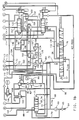
- the reference numeral 10 generally designates a motor vehicle drivetrain including an engine 12 and an automatic transmission 14 of the planetary type having a reverse speed ratio and five forward speed ratios.
- Engine 12 includes a throttle 16 mechanically connected to an operator manipulated device, such as an accelerator pedal (not shown), for regulating the air intake of the engine.
- the engine 12 is fuelled by a conventional method in relation to the air intake to produce output torque in proportion thereto. Such torque is applied to the automatic transmission 14 through an engine output shaft 18.
- the automatic transmission 14 transmits engine output torque to an output shaft 20 through a torque converter 24 and one or more of the fluid operated clutches C1-C5, OC, Reverse clutch CR, and one-way clutches 26-30, such clutches being applied or released according to a predetermined schedule for establishing a desired transmission speed ratio; and defining torque transmitting devices for the automatic transmission.
- an impeller or input member 36 of the torque converter 24 is connected to be rotatably driven by the engine output shaft 18 through an input shell 38.
- Turbine or output member 40 of the torque converter 24 is rotatably driven by the impeller 36 by means of fluid transfer therebetween and is connected to rotatably drive a turbine shaft 42.
- a stator member 44 redirects the fluid which couples the impeller 36 to the turbine 40, the stator member being connected through a one-way device 46 to the housing of automatic transmission 14.
- the torque converter 24 also includes a clutch TCC comprising a clutch plate 50 secured to the turbine shaft 42.
- the clutch plate 50 has a friction surface 52 formed thereon adaptable to be engaged with the inner surface of the input shell 38 to form a direct mechanical drive between the engine output shaft 18 and the turbine shaft 42.
- the clutch plate 50 divides the space between input shell 38 and the turbine 40 into two fluid chambers: an apply chamber 54 and a release chamber 56.
- the turbine shaft 42 is connected as an input to carrier Cf of a forward planetary gearset f.
- Sun Sf is connected to carrier Cf via the parallel combination of one-way clutch 26 (F5) and friction clutch OC.
- the clutch C5 is selectively engageable to ground the sun Sf.
- Ring Rf is connected as an input to the S1r of a compound rearward planetary gearset r via the parallel combination of one-way clutch 28 (F1) and friction clutch C3.
- the clutch C2 selectively connects the ring Rf to ring Rr of rearward planetary gearset r, and the Reverse clutch CR selectively grounds the ring Rr.
- Sun S2r is selectively grounded by clutch C4 or by clutch C1 through the one-way clutch 30 (F2).
- Rear planet axis Pr mechanically couples the pinion gears and is connected as an output to output shaft 20.
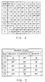
- the upshift from 2nd to 3rd is effected by engaging clutch C5 and releasing clutch OC so that the forward planetary gearset f operates as an overdrive, thereby providing a Nt/No ratio of 1.37.
- Downshifting from 3rd to 2nd is effected by releasing clutch C5 and engaging clutch OC to return the forward planetary gearset f to a lock-up condition.
- the upshift from 3rd and 4th is effected by releasing clutch C5 and engaging clutch OC to return the forward planetary gearset f to a lock-up condition, while releasing clutch C4 and engaging clutch C3 to lock-up the rearward planetary gearset r, one-way clutch 30 (F2) releasing the rear planet axis Pr.
- the turbine speed Nt is transmitted directly to output shaft 20 for a Nt/No ratio of 1.00.
- the downshift 4th to 3rd is effected by releasing clutch OC and engaging clutch C5 to return the forward planetary gearset f to an overdrive condition, while releasing clutch C3 and engaging clutch C4 to apply the turbine speed Nt as an input to the ring Rr.
- the upshift from 4th to 5th is effected by engaging clutch C5 (and releasing clutch OC if engine braking is selected) to operate the forward planetary gearset f in an overdrive condition, thereby providing a Nt/No ratio of 0.74.
- Downshifting from 5th to 4th is effected by releasing clutch C5 (and engaging clutch OC if engine braking is selected).
- a (positive displacement hydraulic) pump 60 is mechanically driven by the engine output shaft 18. Pump 60 receives hydraulic fluid at low pressure from fluid reservoir 64 and filter 65, and supplies line pressure fluid to the transmission control elements via output line 66.
- a pressure regulator valve (PRV) 68 is connected to the output line 66 and serves to regulate the line pressure by returning a controlled portion of the line pressure to fluid reservoir 64 via line 70.
- the PRV 68 is biased at one end by orificed line pressure in line 71 and at the other end by the combination of a spring force, a Reverse ratio fluid pressure in line 72 and a controlled bias pressure in line 74.
- the Reverse fluid pressure is supplied by a Manual Valve 76, described below.
- the controlled bias pressure is supplied by a Line Pressure Bias Valve 78 which develops pressure in relation to the current supplied to (electric) force motor 80.
- Line pressure is supplied as an input to Line Pressure Bias valve 78 via line 82, a pressure limiting valve 84 and filter 85.
- the limited line pressure referred to as ACT FEED pressure, is also supplied as an input to other electrically operated actuators of the control system via line 86.
- the PRV 68 develops a regulated converter feed (CF) pressure for the torque converter 24 in line 88.
- the CF pressure is supplied as an input to TCC Control Valve 90, which, in turn, directs the CF pressure to the release chamber 56 of torque converter 24 via line 92 when open converter operation is desired.
- the return fluid from torque converter 24 is exhausted via line 94, the TCC Control Valve 90, an oil cooler 96 and an orifice 98.
- the TCC Control Valve 90 exhausts the release chamber 56 of torque converter 24 to an orificed exhaust 100, and supplies a regulated TCC apply pressure in line 102 to the apply chamber 54, thereby engaging the clutch TCC.
- the TCC apply pressure in line 102 is developed from line pressure by a TCC Regulator Valve 104.
- Both the TCC Control Valve 90 and the TCC Regulator Valve 104 are spring biased to effect the open converter condition, and in each case, the spring force is opposed by an electrically developed control pressure in line 106.
- the control pressure in line 106 is developed by the (solenoid operated) TCC Bias Valve 108, through a ratiometric regulation of the fluid pressure in line 110.
- TCC Bias Valve 108 When closed converter operation is desired, the solenoid of TCC Bias Valve 108 is pulse-width-modulated (PWM) at a controlled duty cycle to ramp up the bias pressure in line 106. Bias pressures above the pressure required to shift the TCC Control Valve 90 to the closed-converter state are used to control the TCC apply pressure developed in line 102 by TCC Regulator Valve 104. In this way, the TCC Bias Valve 108 is used to control the torque capacity of the clutch TCC when closed converter operation is desired.
- PWM pulse-width-modulated
- the friction clutches C1-C5, OC and CR are activated by conventional (fluid operated) pistons P1-P5, POC and PCR, respectively.
- the pistons are connected to a fluid supply system comprising the Manual Valve 76 referred to above, Shift Valves 120, 122 and 124, and the Accumulators 126, 128 and 130.
- the Manual Valve 76 develops supply pressures for Reverse (REV) and the various forward ranges (DR, D32) in response to driver positioning of a transmission range selector 77.
- the REV, DR and D32 pressures are supplied via lines 72, 132 and 134 to the various Shift Valves 120-124 for application to the fluid operated pistons P1-P5, POC and PCR.
- the Shift Valves 120, 122 and 124 are each spring biased against controlled bias pressures, the controlled bias pressures being developed by the solenoid operated valves A, C and B.
- the accumulators 126, 128 and 130 are used to cushion the apply, and in some cases the release, of clutches C5, C2 and C3, respectively.
- FIG. 3 A chart of the ON/OFF states of valves A, C and B for establishing the various transmission speed ratios is given in Figure 3.
- the solenoids A, B and C are all off.
- line pressure is supplied to piston POC through orifice 176, but the remaining clutches are all disengaged.
- Reverse fluid pressure when generated by Manual Valve 76 in response to driver displacement of transmission range selector 77, is supplied directly to piston P3 via lines 72, 73 and 140, and to piston PCR via lines 72, 142, orifice 144 and Shift Valve 124.
- a garage shift to the forward (Drive) ranges is effected when Manual Valve 76 is moved to the D position, connecting line pressure to the (DR pressure supply) line 132.
- the DR pressure is supplied to the piston P1 via line 146 and orifice 148 to progressively engage clutch C1.
- Solenoid Operated Valves A and C are energised to actuate Shift Valves 120 and 122.
- the Shift Valve 122 directs DR pressure in line 132 to piston P4 via Regulator Valve 150 and line 152.
- the Shift Valve 120 supplies a bias pressure to the Regulator Valve 150 via line 154 to boost the pressure to clutch C4. In this way, clutches C1, C4 and OC are engaged to establish 1st speed ratio.
- a 1-2 upshift is effected by deenergising Solenoid Operated Valve A to return Shift Valve 120 to its default state.
- This routes DR pressure in line 132 to the piston P2 via Shift Valve 120, lines 156, 158 and 162, and orifice 160 to engage the clutch C2.
- Line 162 is also connected as an input to accumulator 128, the backside of which is maintained at a regulated pressure developed by valve 164.
- the engagement of clutch C2 is thereby cushioned as the C2 apply pressure, resisted by spring force, strokes the piston of accumulator 128.
- a 2-1 downshift is effected by energising the Solenoid Operated Valve A.
- a 2-3 upshift is effected by energising Solenoid Operated Valve B to actuate the Shift Valve 124.
- This exhausts the piston POC via orifice 166 to release the clutch OC, and supplies line pressure in output line 66 to piston P5 via orifice 168 and line 170 to progressively engage clutch C5.
- Line 170 is connected via line 172 as an input to accumulator 126, the backside of which is maintained at a regulated pressure developed by valve 164.
- the engagement of clutch C5 is thereby cushioned as the C5 apply pressure, resisted by spring force, strokes the piston of accumulator 126.
- a 3-2 downshift is effected by deenergising the Solenoid Operated Valve B.
- a 3-4 upshift is effected by deenergising Solenoid Operated Valves B and C to return Shift Valves 124 and 122 to their default positions, as depicted in Figures 1a-1b.
- the Shift Valve 124 thereby (1) exhausts piston P5 and accumulator 126 via line 170 and orifice 174 to release clutch C5, and (2) supplies pressure to piston POC via lines 66 and 171 and orifice 176 to engage clutch OC.
- the Shift Valve 122 (1) exhausts piston P4 via line 152 and orifice 178 to release clutch C4, and (2) supplies DR pressure in line 132 to piston P3 via Shift Valve 120, orifice 180 and lines 182, 184, 73 and 140 to engage clutch C3.
- Line 182 is connected via line 186 as an input to accumulator 130, the backside of which is maintained at a regulated pressure developed by valve 164.
- the engagement of clutch C3 is thereby cushioned as the C3 apply pressure, resisted by spring force, strokes the piston of accumulator 130.
- a 4-3 downshift is effected by energising the Solenoid Operated Valves B and C.
- a 4-5 upshift is effected by energising Solenoid Operated Valve B to actuate the Shift Valve 124.
- This exhausts the piston POC via orifice 166 to release the clutch OC, and supplies line pressure in output line 66 to piston P5 via orifice 168 and line 170 to progressively engage clutch P5.
- line 170 is also connected via line 172 as an input to accumulator 126, which cushions the engagement of clutch C5 as the C5 apply pressure, resisted by spring force, strokes the piston of accumulator 126.
- a 5-4 downshift is effected by deenergising the Solenoid Operated Valve B.
- the Solenoid Operated Valves A, B and C, the TCC Bias Valve 108 and the Line Pressure Bias Valve 78 are all controlled by a (computer-based) Transmission Control Unit (TCU) 190 via lines 192-196.
- TCU Transmission Control Unit
- the solenoid operated valves A, B and C require simple on/off controls, while the bias valves 108 and 78 are pulse-width-modulated (PWM).
- PWM pulse-width-modulated
- the control is carried out in response to a number of input signals, including an engine throttle signal %T on line 197, a turbine speed signal Nt on line 198 and an output speed signal No on line 199.
- the engine throttle signal %T is based on the position of throttle 16, as sensed by transducer T; the turbine speed signal Nt is based on the speed of turbine shaft 42, as sensed by sensor 200; and the output speed signal No is based on the speed of output shaft 20, as sensed by sensor 202.
- the TCU 190 executes a series of computer program instructions, represented by the flow diagrams of Figures 7-9 described below.
- the present invention concerns the detection of an abnormal shifting condition referred to as run-through.
- run-through an abnormal shifting condition referred to as run-through.
- the full engagement of the on-coming clutch normally occurs prior to the end of stroke of the respective accumulator 126, 128, 130.
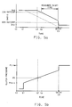
- This condition is graphically depicted by the traces of Figures 4a-4b which respectively represent the actual transmission speed ratio (Nt/No) and the on-coming clutch apply pressure.
- the solenoid states are activated at time t0 to initiate the shift, directing fluid pressure to the respective clutch apply circuit.
- the clutch pressure jumps to an initial level, designated in the lower trace as Pinit.
- the pressure Pinit is determined by the line pressure, the accumulator spring force and the trim pressure applied to the spring side of the accumulator piston.
- the trim pressure is also increased, resulting in an increase in the pressure Pinit.
- the pressure Pinit is decreased when line pressure is decreased.
- the accumulator damper spring begins to compress, and the clutch pressure progressively increases toward line pressure Pline as shown.
- the torque capacity of the on-coming clutch achieves a critical capacity, at which the turbine speed begins to fall and the measured ratio begins its transition from 2nd to 3rd.
- the clutch is fully engaged to complete the ratio progression, as seen in the upper trace.
- the stroke of the accumulator piston is completed at time t4, at which point the clutch pressure rapidly increases to the line pressure Pline, as seen in the lower trace. Since the clutch is fully engaged prior to time t4, the abrupt rise in pressure occurring at the end of the accumulator stroke is not perceived by the occupants of the vehicle.
- shift quality is determined by measuring the actual shift progression time and comparing the measured time with a reference or desired time.
- the best results are achieved by computing the percentage of ratio completion (RATCOMP), and measuring the time elapsed during a predetermined portion of the ratio progression, as graphically illustrated in Figure 4a.
- the measured shift time is defined as the interval between 20% and 80% ratio completion, or the interval between times ta and tb.
- Figures 5a-5b graphically depict an upshift carried out at an abnormally low line pressure, resulting in a run-through condition. Since the entire pressure profile is correspondingly lowered, the achievement of critical clutch pressure P1 (time t2) is significantly delayed, compared to the normal shift of Figures 4a-4b. Hence, the start of ratio change is likewise delayed, and the shift is still in progress at the end of the accumulator stroke. In the illustrated example, time t3 (80% RATCOMP), time tb (end of accumulator stroke) and time t4 (end of shift) occur substantially at the same time, as indicated. The rapid rise in clutch pressure associated with the end of accumulator stroking produces an abrupt increase in the rate of shift completion, resulting in a poor quality shift.
- time t3 80% RATCOMP
- time tb end of accumulator stroke
- time t4 end of shift
- the control of this invention avoids the above-described operation by adaptively increasing the pressure for subsequent shifting regardless of the shift time error when the occurrence of a run-through condition is detected.
- Run-through shifting is detected, according to this invention, by periodically sampling the transmission speed ratio in the course of the upshift inertia phase to determine the average speed ratio during the sampling period.
- a normal upshift as depicted in Figures 4a-4b
- the average ratio is substantially equal to the midpoint of the two speed ratios.
- the ratio progression is delayed or carried out at a significantly lower rate, resulting in an average ratio significantly higher than for the normal shift.
- Figures 6a-6b The procedure for determining the average speed ratio according to this invention is graphically depicted in Figures 6a-6b.
- Figure 6a repeats the normal ratio progression of Figure 4a
- Figure 6b repeats the run-through ratio progression of Figure 5a.
- the ratio is periodically sampled in the interval of 20%-80% ratio completion.
- the tick marks shown on the ratio progression traces represent the sample intervals.
- the control is allowed to update the adaptive pressure value in relation to the difference between the measured shift time and a desired shift time, as in the above-mentioned US patents.
- This condition is observed in Figure 6a.
- the adaptive pressure amount is increased regardless of the measured shift time in order to eliminate the run-through condition in the next shift to the same speed ratio.
- the flow diagram of Figure 7 represents a main or executive computer program which is periodically executed in the course of vehicle operation in carrying out the control of this invention.
- the block 240 designates a series of program instructions executed at the initiation of each period of vehicle operation for setting various terms and timer values to an initial condition. Thereafter, the blocks 242-250 are sequentially and repeatedly executed as indicated by the flow diagram line 252.
- the TCU 190 reads the various inputs referenced in Figure 1a and updates the loop timers, if any.
- the block 254 determines the desired speed ratio Rdes and required states of solenoid operated valves A, B and C for achieving the desired speed ratio.
- the desired ratio Rdes may be determined in a conventional manner as a predefined function of engine throttle position %T and output speed No.
- the block 248 converts the desired line pressure LPdes to a PWM duty cycle for force motor 80, and suitably energises the various electro-hydraulic elements, including the force motor 80, the TCC bias valve 108, and solenoid operated valves A, B and C.
- the block 250 described in further detail in the flow diagram of Figure 9, develops adaptive pressure corrections based on the measured inertia phase interval and whether a run-through condition is detected.
- the block 260 is first executed to determine if the automatic transmission 14 is in an engine braking mode, if a garage shift is in progress, or if the Reverse range is engaged. If any of these conditions are true, the block 262 is executed to determine the desired line pressure LPdes using mode-specific look-up tables, not described herein. Otherwise, the blocks 264-272 are executed to look-up the base line pressure LPdes as a function of throttle position %T and vehicle speed Nv, to apply the appropriate offsets, to look-up and apply the cumulative adaptive correction amount LPad, and to compensate for barometric pressure.
- the offsets identified in block 266 include a gear-related offset OSgear, an engine power enrichment offset OSpe, a downshift offset OSds, and a jump-shift offset OSusj.
- the gear-related offset OSgear is determined as a function of gear (solenoid state), throttle position %T, and the state of a driver preference mode (Normal/Performance).
- the power enrichment offset OSpe is determined as a function of engine speed Ne.
- the downshift offset OSds is determined as a function of gear and vehicle speed Nv
- jump-shift offset OSusj is determined as a function of the shift type.
- the barometric pressure, or altitude, compensation of block 272 is carried out with a factor Kalt determined as a function of the throttle position %T and the barometric pressure, as may be determined from an engine manifold absolute pressure sensor (not shown).
- the adaptive pressure correction LPad is determined as a function of the throttle position %T and gear, as indicated at block 268. Preferably, this look-up involves an interpolation between a pair of adjacent cells of a look-up array, based on engine throttle position. As indicated at block 270, the adaptive correction LPad is simply added to the base pressure value to form the desired pressure value LPdes.
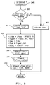
- the TCU 190 determines the inertia phase time of each normal upshift through the use of an inertia phase timer IP TIMER and compares it to a reference time IPdes. At the same time, the TCU 190 determines the average speed ratio during the inertia phase and compares it to a desired average speed ratio which would be observed during normal shifting. If the determined average speed ratio is within a reference amount of the desired average speed ratio, the TCU 190 updates the adaptive pressure term LPad in relation to the comparison between the measured and reference inertia phase times. If the determined average speed ratio exceeds the desired average by at least the reference amount, the TCU 190 independently increases the adaptive pressure term LPad to prevent the occurrence of a run-through condition in the next such shift.
- the blocks 282-296 are executed to determine the elapsed time and average speed ratio during the inertia phase interval.
- the inertia phase interval for the purposes of this control is defined as the interval during which the percentage of speed ratio change completion (%RATCOMP) progresses from 20% to 80%.
- %RATCOMP percentage of speed ratio change completion
- the block 286 is executed to start an inertia phase timer, IP TIMER, and to initialise the average ratio (Ravg) and sample number (SL) to zero. So long as %RATCOMP is less than 80%, as determined at block 288, the block 290 is executed to periodically update the term Ravg in accordance with the current speed ratio value Ract, while incrementing the sample number SL.
- the block 292 is executed to compute the average speed ratio Ravg as (Ravg/SL). If the computed average speed ratio Ravg exceeds the midpoint of the old and new speed ratios (Rmp) by more than a reference amount Ref, as determined at block 294, the block 298 is executed to increase the adaptive pressure correction term LPad by a quantity Krt dependent on the shift type. Otherwise, the blocks 296 and 302-308 are executed to stop the IP TIMER, and to update the adaptive correction term LPad as set forth in the above-reference US patents.
- the block 302 determines if the entry conditions for adaptive updating are satisfied. Such conditions may include: normal pattern shift, transmission oil temperature TEMP and throttle position %T within limits, no large throttle changes in the shift, not a jump-shift, and not a step-out shift. If the entry conditions are not met, no updating of the adaptive pressure correction amount is carried out. If the entry conditions are met, the blocks 304 and 306 look-up the desired shift time IPdes and the adaptive pressure correction amount Lpmod. As noted at block 304, the desired shift time IPdes is determined as a function of gear and the throttle position %Tinit at the initiation of the shift.
- the adaptive modifier LPmod is determined as a function of gear and the error or difference between the measured shift time IP TIMER and the desired shift time IPdes.
- the block 308 updates a cumulative pressure correction amount LPad in accordance with the adaptive modifier LPmod.
Landscapes
- Engineering & Computer Science (AREA)
- General Engineering & Computer Science (AREA)
- Mechanical Engineering (AREA)
- Control Of Transmission Device (AREA)
Claims (6)
- Dispositif de commande pour transmission automatique (14) d'un véhicule motorisé, transmission automatique incluant un dispositif de transmission de couple (C1-C5) qui est commandé hydrauliquement et qui s'embraye pour décaller la transmission automatique d'un rapport des vitesses actuel vers un rapport des vitesses cible, une source (60) de pression hydraulique, des moyens de régulation (68) pour régler la pression hydraulique en correspondance avec une commande de pression prédéterminée pour réaliser une pression de ligne réglée (Pline), une valve de décalage (120, 122) qui fonctionne lors de son actionnement pour diriger la pression de ligne réglée vers le dispositif de transmission de couple pour embrayer ce dispositif de transmission de couple, et des moyens accumulateurs de fluide (126-130) pour absorber une portion du fluide hydraulique dirigée vers le dispositif de transmission de couple par la valve de décalage pendant un intervalle de course du décalage, le dispositif de commande comprenant des moyens qui agissent pendant une période d'échantillonnage, que définit une progression du rapport de vitesses, à partir du rapport actuel de vitesses vers le rapport des vitesses cible, pour échantillonner périodiquement le rapport de vitesses; et des moyens qui agissent lors de l'achèvement de la période d'échantillonnage pour déterminer un signal de rapport moyen qui correspond à la moyenne des rapports de vitesses échantillonnés périodiquement; caractérisé par des moyens de détection pour comparer le signal de rapport moyen déterminé à un rapport moyen voulu pour détecter une condition anormale de décalage dans laquelle le changement de rapport des vitesses est accompli après l'intervalle de course; et des moyens pour ajuster la commande de pression prédéterminée dans un sens à augmenter la pression de ligne réglée dans un décalage ultérieur vers le rapport des vitesses cible en fonction de la détection d'une condition anormale de décalage, afin ainsi d'éviter une répétition de la condition anormale de décalage.
- Dispositif de commande selon la revendication 1, dans lequel la condition anormale de décalage est détectée quand le signal de rapport moyen déterminé dépasse le rapport moyen voulu d'au moins un écart prédétermine.
- Dispositif de commande selon la revendication 1 ou 2, dans lequel le rapport moyen voulu est déterminé en correspondance avec une médiane du rapport des vitesses actuel et le rapport des vitesses cible.
- Dispositif de commande pour transmission automatique (14) d'un véhicule motorisé, la transmission automatique incluant un dispositif de transmission de couple (C1-C5) qui est commandé hydrauliquement et qui s'embraye pour décaler la transmission automatique d'un rapport des vitesses actuel vers un rapport des vitesses cible, une source (60) de pression hydraulique, des moyens de régulation (68) pour régler la pression hydraulique en correspondance avec une commande de pression prédéterminée pour réaliser une pression de ligne réglée (Pline), une valve de décalage de vitesses (120, 122) qui fonctionne lors de son actionnement pour diriger la pression de ligne réglée vers le dispositif de transmission de couple pour embrayer ce dispositif de transmission de couple, et des moyens accumulateurs de fluide (126-130) pour absorber une portion du fluide hydraulique dirigée vers le dispositif de transmission de couple par la valve de décalage pendant un intervalle de course du décalage, le dispositif de commande comprenant des moyens qui agissent pendant le décalage vers le rapport des vitesses cible pour mesurer un temps de décalage qui correspond à la durée du changement détecté dans le rapport de vitesses; et des moyens de commande de qualité de décalage pour ajuster la commande de pression prédéterminée sur la base d'une déviation détectée entre le temps mesuré de décalage et un temps prédéterminé de décalage qui est caractéristique d'une bonne qualité de changement de vitesses dans des conditions normales; caractérisé par des moyens pour comparer une mesure du rapport des vitesses moyen pendant le changement détecté en rapport des vitesses à un rapport des vitesses moyen voulu afin de détecter une condition anormale de décalage dans laquelle le changement en rapport des vitesses est accompli après l'intervalle de course; et des moyens de dérogation pour déroger à l'ajustement des moyens de commande de qualité de décalage en réaction à une détection de la condition anormale de décalage et, au lieu, d'ajuster la commande de pression prédéterminée dans un sens qui augmente la pression de ligne réglée dans un décalage ultérieur vers le rapport des vitesses cible, afin d'empêcher ainsi une répétition de la condition anormale de décalage.
- Dispositif de commande selon la revendication 4, dans lequel la condition anormale de décalage est détectée quand le rapport moyen mesuré dépasse le rapport moyen voulu d'au moins une quantité prédéterminée.
- Dispositif de commande selon la revendication 4 ou la revendication 5, dans lequel le rapport moyen voulu est déterminé en correspondance avec une médiane du rapport des vitesses actuel et le rapport des vitesses cible.
Applications Claiming Priority (2)
| Application Number | Priority Date | Filing Date | Title |
|---|---|---|---|
| US07/894,982 US5289741A (en) | 1992-06-08 | 1992-06-08 | Adaptive transmission pressure control with run-through detection |
| US894982 | 1992-06-08 |
Publications (2)
| Publication Number | Publication Date |
|---|---|
| EP0574061A1 EP0574061A1 (fr) | 1993-12-15 |
| EP0574061B1 true EP0574061B1 (fr) | 1995-11-15 |
Family
ID=25403782
Family Applications (1)
| Application Number | Title | Priority Date | Filing Date |
|---|---|---|---|
| EP93201435A Expired - Lifetime EP0574061B1 (fr) | 1992-06-08 | 1993-05-19 | Dispositif de commande pour une transmission automatique |
Country Status (6)
| Country | Link |
|---|---|
| US (1) | US5289741A (fr) |
| EP (1) | EP0574061B1 (fr) |
| JP (1) | JPH0786389B2 (fr) |
| AU (1) | AU644982B1 (fr) |
| CA (1) | CA2089718C (fr) |
| DE (1) | DE69300798T2 (fr) |
Families Citing this family (16)
| Publication number | Priority date | Publication date | Assignee | Title |
|---|---|---|---|---|
| JP3283323B2 (ja) * | 1993-03-26 | 2002-05-20 | マツダ株式会社 | 自動変速機の変速時油圧制御装置 |
| US5458545A (en) * | 1994-01-21 | 1995-10-17 | Chrysler Corporation | Adaptive line pressure control for an electronic automatic transmission |
| KR100220054B1 (ko) * | 1994-07-29 | 1999-09-01 | 정몽규 | 자동 변속기의 고장예측장치 및 그 방법 |
| JP3374165B2 (ja) * | 1994-11-30 | 2003-02-04 | ジヤトコ株式会社 | 自動変速機の変速油圧制御装置 |
| JP3374166B2 (ja) * | 1994-11-30 | 2003-02-04 | ジヤトコ株式会社 | 自動変速機の学習制御装置 |
| JP3374167B2 (ja) * | 1994-12-01 | 2003-02-04 | ジヤトコ株式会社 | 自動変速機の学習制御装置 |
| US5551930A (en) * | 1995-04-13 | 1996-09-03 | Caterpillar Inc. | Adaptive control method for an automatic transmission |
| US5580332A (en) * | 1995-04-13 | 1996-12-03 | Caterpillar Inc. | Method for determining the fill time of a transmission clutch |
| US6115661A (en) * | 1998-04-09 | 2000-09-05 | Caterpillar Inc. | End-of-fill detector for a fluid actuated clutch |
| US5950789A (en) * | 1998-04-27 | 1999-09-14 | Caterpillar Inc. | End of fill detector for a fluid actuated clutch |
| US7486996B2 (en) * | 2005-09-26 | 2009-02-03 | Eaton Corporation | Transmission control unit having pressure transducer package |
| WO2012133808A1 (fr) * | 2011-03-31 | 2012-10-04 | アイシン・エィ・ダブリュ株式会社 | Équipement et procédé de commande d'un équipement de transmission |
| US9500197B2 (en) | 2012-05-18 | 2016-11-22 | Gm Global Technology Operations, Llc | Pump assembly with multiple gear ratios |
| CN103717862B (zh) * | 2012-07-16 | 2015-04-29 | 本田技研工业株式会社 | 车辆的控制装置 |
| US9546728B2 (en) | 2014-04-08 | 2017-01-17 | GM Global Technology Operations LLC | Balanced binary pump for CVT transmission |
| CN113048161B (zh) * | 2021-03-08 | 2022-07-19 | 重庆青山工业有限责任公司 | 一种湿式dct离合器充油过程的调节控制方法 |
Family Cites Families (14)
| Publication number | Priority date | Publication date | Assignee | Title |
|---|---|---|---|---|
| SE420295B (sv) * | 1980-11-28 | 1981-09-28 | Saab Scania Ab | Forfarande for automatiskt vexelval i en fordonstransmission |
| US4653350A (en) * | 1985-11-29 | 1987-03-31 | General Motors Corporation | Adaptive direct pressure shift control for a motor vehicle transmission |
| JPS6353349A (ja) * | 1986-08-20 | 1988-03-07 | Aisin Warner Ltd | 電子制御式自動変速機 |
| US5115395A (en) * | 1987-03-13 | 1992-05-19 | Borg-Warner Automotive, Inc. | Pulse width modulation technique |
| JPH0781631B2 (ja) * | 1987-12-25 | 1995-09-06 | 日産自動車株式会社 | 自動変速機のライン圧制御装置 |
| JPH0781627B2 (ja) * | 1988-02-05 | 1995-09-06 | 日産自動車株式会社 | 自動変速機のライン圧制御装置 |
| US5005441A (en) * | 1988-04-15 | 1991-04-09 | Nissan Motor Co., Ltd. | Line pressure control for automatic transmission |
| JP2615872B2 (ja) * | 1988-07-06 | 1997-06-04 | 日産自動車株式会社 | 自動変速機のライン圧制御装置 |
| JPH0246365A (ja) * | 1988-08-08 | 1990-02-15 | Nissan Motor Co Ltd | 自動変速機のライン圧制御装置 |
| JPH02304261A (ja) * | 1989-05-19 | 1990-12-18 | Nissan Motor Co Ltd | 自動変速機のライン圧制御装置 |
| KR920010906B1 (ko) * | 1989-08-23 | 1992-12-21 | 마쯔다 가부시기가이샤 | 자동변속기의 라인압 제어장치 |
| JP3042848B2 (ja) * | 1989-12-26 | 2000-05-22 | アイシン・エィ・ダブリュ株式会社 | 電子制御式自動変速機 |
| US5123302A (en) * | 1990-12-24 | 1992-06-23 | Ford Motor Company | Automatic transmission gearshift control having feedforward response of clutch and its hydraulic actuation |
| US5163342A (en) * | 1992-04-03 | 1992-11-17 | General Motors Corporation | Adaptive transmission pressure control with run-through detection |
-
1992
- 1992-06-08 US US07/894,982 patent/US5289741A/en not_active Expired - Fee Related
-
1993
- 1993-02-17 CA CA002089718A patent/CA2089718C/fr not_active Expired - Fee Related
- 1993-05-19 EP EP93201435A patent/EP0574061B1/fr not_active Expired - Lifetime
- 1993-05-19 DE DE69300798T patent/DE69300798T2/de not_active Expired - Lifetime
- 1993-05-24 AU AU38754/93A patent/AU644982B1/en not_active Ceased
- 1993-06-08 JP JP5137749A patent/JPH0786389B2/ja not_active Expired - Lifetime
Also Published As
| Publication number | Publication date |
|---|---|
| US5289741A (en) | 1994-03-01 |
| DE69300798T2 (de) | 1996-04-25 |
| DE69300798D1 (de) | 1995-12-21 |
| JPH0786389B2 (ja) | 1995-09-20 |
| AU644982B1 (en) | 1993-12-23 |
| CA2089718C (fr) | 1997-02-18 |
| JPH06221421A (ja) | 1994-08-09 |
| EP0574061A1 (fr) | 1993-12-15 |
| CA2089718A1 (fr) | 1993-12-09 |
Similar Documents
| Publication | Publication Date | Title |
|---|---|---|
| EP0498480B1 (fr) | Méthode de commande de rétrogradation à deux états transitoires pour une transmission automatique | |
| EP0235892B1 (fr) | Rétrogradage sous charge d'un embrayage à l'autre dans une transmission automatique de véhicule à moteur | |
| EP0574061B1 (fr) | Dispositif de commande pour une transmission automatique | |
| EP0564016B1 (fr) | Dispositif de commande pour transmission automatique | |
| EP0816720B1 (fr) | Contrôle de changement de vitesse stabilisé pour transmission automatique | |
| US5152192A (en) | Dynamic shift control for an automatic transmission | |
| CA2064308C (fr) | Commande d'embrayages en serie a boucle ouverte et regulation de chevauchement | |
| EP0310275A2 (fr) | Modification du schéma de commutation en cas de défaillance pour une transmission, commandée électroniquement | |
| EP0537809B1 (fr) | Système à commande de pression de ligne pour une transmission automatique | |
| EP0564015B1 (fr) | Dispositif de commande pour transmission automatique | |
| EP0525853B1 (fr) | Procédé de commande d'une transmission automatique | |
| CA2097689C (fr) | Commande d'embrayage a compensation basee sur l'acceleration | |
| EP0498481B1 (fr) | Méthode de commande pour passer en deux états transitoires à des rapports supérieurs dans une transmission automatique | |
| US5737712A (en) | Fuzzy logic adaptive shift control | |
| US5911647A (en) | Control apparatus for automatic transmission |
Legal Events
| Date | Code | Title | Description |
|---|---|---|---|
| PUAI | Public reference made under article 153(3) epc to a published international application that has entered the european phase |
Free format text: ORIGINAL CODE: 0009012 |
|
| AK | Designated contracting states |
Kind code of ref document: A1 Designated state(s): DE FR GB |
|
| 17P | Request for examination filed |
Effective date: 19931224 |
|
| R17P | Request for examination filed (corrected) |
Effective date: 19931222 |
|
| 17Q | First examination report despatched |
Effective date: 19950222 |
|
| GRAA | (expected) grant |
Free format text: ORIGINAL CODE: 0009210 |
|
| AK | Designated contracting states |
Kind code of ref document: B1 Designated state(s): DE FR GB |
|
| REF | Corresponds to: |
Ref document number: 69300798 Country of ref document: DE Date of ref document: 19951221 |
|
| ET | Fr: translation filed | ||
| PLBE | No opposition filed within time limit |
Free format text: ORIGINAL CODE: 0009261 |
|
| STAA | Information on the status of an ep patent application or granted ep patent |
Free format text: STATUS: NO OPPOSITION FILED WITHIN TIME LIMIT |
|
| 26N | No opposition filed | ||
| PGFP | Annual fee paid to national office [announced via postgrant information from national office to epo] |
Ref country code: GB Payment date: 20000502 Year of fee payment: 8 |
|
| PGFP | Annual fee paid to national office [announced via postgrant information from national office to epo] |
Ref country code: FR Payment date: 20000515 Year of fee payment: 8 |
|
| PG25 | Lapsed in a contracting state [announced via postgrant information from national office to epo] |
Ref country code: GB Free format text: LAPSE BECAUSE OF NON-PAYMENT OF DUE FEES Effective date: 20010519 |
|
| GBPC | Gb: european patent ceased through non-payment of renewal fee |
Effective date: 20010519 |
|
| PG25 | Lapsed in a contracting state [announced via postgrant information from national office to epo] |
Ref country code: FR Free format text: LAPSE BECAUSE OF NON-PAYMENT OF DUE FEES Effective date: 20020131 |
|
| REG | Reference to a national code |
Ref country code: DE Ref legal event code: R081 Ref document number: 69300798 Country of ref document: DE Owner name: GENERAL MOTORS LLC ( N. D. GES. D. STAATES DEL, US Free format text: FORMER OWNER: GENERAL MOTORS COMPANY, DETROIT, MICH., US Effective date: 20110428 Ref country code: DE Ref legal event code: R081 Ref document number: 69300798 Country of ref document: DE Owner name: GENERAL MOTORS LLC ( N. D. GES. D. STAATES DEL, US Free format text: FORMER OWNER: GENERAL MOTORS COMPANY, DETROIT, US Effective date: 20110428 |
|
| PGFP | Annual fee paid to national office [announced via postgrant information from national office to epo] |
Ref country code: DE Payment date: 20110511 Year of fee payment: 19 |
|
| REG | Reference to a national code |
Ref country code: DE Ref legal event code: R119 Ref document number: 69300798 Country of ref document: DE Effective date: 20121201 |
|
| PG25 | Lapsed in a contracting state [announced via postgrant information from national office to epo] |
Ref country code: DE Free format text: LAPSE BECAUSE OF NON-PAYMENT OF DUE FEES Effective date: 20121201 |