EP0574321A1 - Anlage zum Abfüllen von Flaschen mit einer Flüssigkeit - Google Patents
Anlage zum Abfüllen von Flaschen mit einer Flüssigkeit Download PDFInfo
- Publication number
- EP0574321A1 EP0574321A1 EP93401490A EP93401490A EP0574321A1 EP 0574321 A1 EP0574321 A1 EP 0574321A1 EP 93401490 A EP93401490 A EP 93401490A EP 93401490 A EP93401490 A EP 93401490A EP 0574321 A1 EP0574321 A1 EP 0574321A1
- Authority
- EP
- European Patent Office
- Prior art keywords
- valve
- bottle
- seat
- cannula
- liquid
- Prior art date
- Legal status (The legal status is an assumption and is not a legal conclusion. Google has not performed a legal analysis and makes no representation as to the accuracy of the status listed.)
- Withdrawn
Links
- 239000007788 liquid Substances 0.000 title claims abstract description 33
- 238000009434 installation Methods 0.000 title claims abstract description 25
- 238000006073 displacement reaction Methods 0.000 claims abstract description 9
- 238000005406 washing Methods 0.000 claims description 9
- 230000000903 blocking effect Effects 0.000 claims description 2
- 230000000295 complement effect Effects 0.000 description 3
- 238000004321 preservation Methods 0.000 description 2
- 241000894006 Bacteria Species 0.000 description 1
- 238000009825 accumulation Methods 0.000 description 1
- 239000000428 dust Substances 0.000 description 1
- 230000000694 effects Effects 0.000 description 1
- 230000004048 modification Effects 0.000 description 1
- 238000012986 modification Methods 0.000 description 1
- 230000003647 oxidation Effects 0.000 description 1
- 238000007254 oxidation reaction Methods 0.000 description 1
- 230000035755 proliferation Effects 0.000 description 1
- 238000005096 rolling process Methods 0.000 description 1
- 238000010408 sweeping Methods 0.000 description 1
Images


Classifications
-
- B—PERFORMING OPERATIONS; TRANSPORTING
- B67—OPENING, CLOSING OR CLEANING BOTTLES, JARS OR SIMILAR CONTAINERS; LIQUID HANDLING
- B67C—CLEANING, FILLING WITH LIQUIDS OR SEMILIQUIDS, OR EMPTYING, OF BOTTLES, JARS, CANS, CASKS, BARRELS, OR SIMILAR CONTAINERS, NOT OTHERWISE PROVIDED FOR; FUNNELS
- B67C3/00—Bottling liquids or semiliquids; Filling jars or cans with liquids or semiliquids using bottling or like apparatus; Filling casks or barrels with liquids or semiliquids
- B67C3/02—Bottling liquids or semiliquids; Filling jars or cans with liquids or semiliquids using bottling or like apparatus
- B67C3/22—Details
- B67C3/26—Filling-heads; Means for engaging filling-heads with bottle necks
- B67C3/2614—Filling-heads; Means for engaging filling-heads with bottle necks specially adapted for counter-pressure filling
- B67C3/2617—Filling-heads; Means for engaging filling-heads with bottle necks specially adapted for counter-pressure filling the liquid valve being opened by mechanical or electrical actuation
-
- B—PERFORMING OPERATIONS; TRANSPORTING
- B67—OPENING, CLOSING OR CLEANING BOTTLES, JARS OR SIMILAR CONTAINERS; LIQUID HANDLING
- B67C—CLEANING, FILLING WITH LIQUIDS OR SEMILIQUIDS, OR EMPTYING, OF BOTTLES, JARS, CANS, CASKS, BARRELS, OR SIMILAR CONTAINERS, NOT OTHERWISE PROVIDED FOR; FUNNELS
- B67C3/00—Bottling liquids or semiliquids; Filling jars or cans with liquids or semiliquids using bottling or like apparatus; Filling casks or barrels with liquids or semiliquids
- B67C3/001—Cleaning of filling devices
- B67C3/002—Cleaning of filling devices using cups or dummies to be placed under the filling heads
- B67C3/004—Cleaning of filling devices using cups or dummies to be placed under the filling heads permanently attached to the filling machine and movable between a rest and a working position
-
- B—PERFORMING OPERATIONS; TRANSPORTING
- B67—OPENING, CLOSING OR CLEANING BOTTLES, JARS OR SIMILAR CONTAINERS; LIQUID HANDLING
- B67C—CLEANING, FILLING WITH LIQUIDS OR SEMILIQUIDS, OR EMPTYING, OF BOTTLES, JARS, CANS, CASKS, BARRELS, OR SIMILAR CONTAINERS, NOT OTHERWISE PROVIDED FOR; FUNNELS
- B67C3/00—Bottling liquids or semiliquids; Filling jars or cans with liquids or semiliquids using bottling or like apparatus; Filling casks or barrels with liquids or semiliquids
- B67C3/02—Bottling liquids or semiliquids; Filling jars or cans with liquids or semiliquids using bottling or like apparatus
- B67C3/06—Bottling liquids or semiliquids; Filling jars or cans with liquids or semiliquids using bottling or like apparatus using counterpressure, i.e. filling while the container is under pressure
- B67C3/10—Bottling liquids or semiliquids; Filling jars or cans with liquids or semiliquids using bottling or like apparatus using counterpressure, i.e. filling while the container is under pressure preliminary filling with inert gases, e.g. carbon dioxide
-
- B—PERFORMING OPERATIONS; TRANSPORTING
- B67—OPENING, CLOSING OR CLEANING BOTTLES, JARS OR SIMILAR CONTAINERS; LIQUID HANDLING
- B67C—CLEANING, FILLING WITH LIQUIDS OR SEMILIQUIDS, OR EMPTYING, OF BOTTLES, JARS, CANS, CASKS, BARRELS, OR SIMILAR CONTAINERS, NOT OTHERWISE PROVIDED FOR; FUNNELS
- B67C3/00—Bottling liquids or semiliquids; Filling jars or cans with liquids or semiliquids using bottling or like apparatus; Filling casks or barrels with liquids or semiliquids
- B67C3/02—Bottling liquids or semiliquids; Filling jars or cans with liquids or semiliquids using bottling or like apparatus
- B67C3/22—Details
- B67C3/26—Filling-heads; Means for engaging filling-heads with bottle necks
- B67C3/2637—Filling-heads; Means for engaging filling-heads with bottle necks comprising a liquid valve opened by relative movement between the container and the filling head
-
- B—PERFORMING OPERATIONS; TRANSPORTING
- B67—OPENING, CLOSING OR CLEANING BOTTLES, JARS OR SIMILAR CONTAINERS; LIQUID HANDLING
- B67C—CLEANING, FILLING WITH LIQUIDS OR SEMILIQUIDS, OR EMPTYING, OF BOTTLES, JARS, CANS, CASKS, BARRELS, OR SIMILAR CONTAINERS, NOT OTHERWISE PROVIDED FOR; FUNNELS
- B67C3/00—Bottling liquids or semiliquids; Filling jars or cans with liquids or semiliquids using bottling or like apparatus; Filling casks or barrels with liquids or semiliquids
- B67C3/02—Bottling liquids or semiliquids; Filling jars or cans with liquids or semiliquids using bottling or like apparatus
- B67C3/22—Details
- B67C3/26—Filling-heads; Means for engaging filling-heads with bottle necks
- B67C2003/2651—The liquid valve being carried by the vent tube
Definitions
- This installation consists of a barrel rotatably mounted on a vertical axis and comprising at its periphery several filling heads connected to a reservoir containing the filling liquid, the lower end of these heads being provided with a first valve, actuated by the bottle during their relative displacement, this first valve blocking the flow of the liquid towards the bottle placed on the head, installation characterized in that a second valve is placed under the first valve to be actuated, during the relative axial displacement of the bottle and of the head, before actuation of the first valve, this second valve being connected to a source of gas under pressure to introduce this gas into the bottle before the introduction of the liquid.
- the head comprises an axially movable cannula, the upper end of which opens into a zone subjected to air pressure situated above the liquid in the reservoir and the lower end of which is surrounded by the first and second valves arranged one above the other for their successive actuation, this arrangement being such that this cannula occupies two axial positions corresponding, one to a closed position of the cannula, the other to an open position of the cannula, independently of the open and closed positions of the first and second valves.
- the second valve arranged under the first valve to be actuated by the bottle before the actuation of the first valve, comprises a first valve seat formed between the first and the second valves.
- the two seats corresponding to the two closed positions of the second valve are provided each time between the first and the second valves.
- the present invention therefore aims to achieve an installation for filling bottles with a liquid, which ensures only by a relative movement of the head and the bottles to be filled, a succession of operations such as before filling the bottle with a liquid a clean gas is introduced into this bottle the preservation of the characteristics of the liquid and in particular suitable for avoiding the modification of its taste qualities, its oxidation or the proliferation of bacteria.
- This installation consists of a barrel 1 rotatably mounted on an axis 2 of a frame 3, this barrel 1 comprising at its periphery a plurality of regularly distributed filling heads 4, of vertical axis XX, that is to say - say parallel to axis 2.
- Each head consists of a body 5, the upper end of which comprises two vertical tubes 6 opening through their upper end to the lower end of a withdrawal tank 7 containing the liquid 8 to be introduced into the bottles.
- This body 5 has below the tubes 6 an axial core 9 surrounded by a skirt 10 open at its lower end.
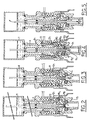
- a cannula 11 In the axis of the core 9 is mounted with sealed sliding a cannula 11 whose upper end opens into the withdrawal tank 7 above the level of the liquid 8 while the closed lower end is provided with lateral orifices 111 located near this closed end (see Figure 4).
- the core 9 is surrounded by a first valve 12 movable axially against a spring 13, this first valve 12 forming at 121 a valve seat with complementary surfaces of the core 9.
- This first valve 12 delimits with the core 9 and above the seat 12 ann, an annular passage 81 for the liquid 8 from the withdrawal tank and is extended, under this seat 121, by a siphon device 82 also of annular shape. ending in an annular passage 83 at a liquid flow spout 8 formed between deflectors 91 of the lower end of the core 9 and the lower flange 122 of the valve 12.
- the first valve 12 is mounted to slide axially against the spring 13 while being guided in leaktight manner by its upper end on the internal wall of a skirt 14.
- a second valve 15 is arranged which is guided in axial sliding and sealed at 151 on the internal wall of the skirt 10.
- This second valve 15 has an annular support zone 152 for the edge of the neck of the bottle 17 to be filled, as well as two zones forming with zones complementary to the first valve 12, two valve seats, the upper one 154 or first seat, the other lower 153 or second seat.
- This second valve 15 is arranged, for its actuation, under the first valve 12 so that when the bottle 17 is lifted, the latter first comes to bear on the bearing surface 152 of the valve 15 in order to lift this valve 15 and open the upper seat 154 against the spring 16 before the first valve 12 is raised against the spring 13.
- these two upper 154 and lower 153 seats of the second valve are arranged one above the other in an axial direction, the upper seat 154 being arranged so as to be closed when the second valve 15 occupies its position the lower ( Figure 1), the lower seat 153 being arranged to be closed when this second valve 15 occupies its highest position relative to the first valve (see Figure 4).
- these two seats 153, 154 formed between the first and the second valves are arranged so as to produce, during the axial displacement of the second valve 15, an open position of this valve between two determined closing positions, for the low position of the second valve 15 by closing the upper valve seat 154 and, for the high position of this valve 15 by closing the lower valve seat 153.
- This intermediate opening position corresponds to the introduction into the bottle 17 of a pressurized gas from a reservoir 18 and opening inside the outer skirt 10 above of the upper seat 154 of the second valve 15.
- This reservoir 18 contains the gas intended to ensure the preservation of the characteristics of the liquid introduced into the bottle and is at a pressure higher than that of the air located in the withdrawal tank 7 above the level of the liquid 8.
- each bottle 17 to produce the actuation of the second valve 15 before the actuation of the first valve 12 is obtained from a circular cam 19 (see FIG. 1) arranged coaxially with the axis 2 and on which comes lean on a roller 20 mounted on a slide 21 parallel to the axis 2, this slide being guided by slides 22 of the frame 1.
- each slide 21 supports a harness 23 on which is placed a bottle 17 to be filled.
- the cannula 11 is movable downhill along the axis XX of the head 4 by means of a roller 25 cooperating with an adjustable circular cam sector 24.
- a second fixed cam sector 241 cooperates with this roller for the ascent of the cannula 11.
- the second valve 15 opens by its seat 154 while the first valve 12 is closed by its seat 121.
- the gas contained in the tank 18 then flows, through the two open seats 154 and 15 dans, into the bottle 17, until the pressures of the bottle and the tank 18 are balanced.
- the circular cam 24 then controls the descent of the cannula 11 via the roller 25 so that the air and the gas contained in the bottle escape through the cannula towards the upper zone of the withdrawal tank 7 while the reservoir 18 continues to introduce gas into the bottle.
- the flow of liquid is deflected towards the internal wall of the neck of the bottle 17 due to the deflectors 91.
- This third stage of operation (FIG. 4) for which the second valve 15 is closed and the first valve 12 open, therefore corresponds to the filling of the bottle with liquid from the reservoir 7, the cannula 11 being, in this position, open by its 111 holes to allow the evacuation of gas to the upper area of the tank 7, as the bottle is filled with the liquid.
- the circular cam 19 controls the descent of the bottle into a position corresponding to that of FIG. 3, the first valve 12 being closed again to interrupt the flow of the liquid, while the lower valve 15 is in its open intermediate position again allowing the gas from the reservoir 18 to enter the bottle (see FIG. 5).
- the circular cam 24 controls the gradual descent of the cannula 11 to a determined level corresponding to the desired level of the liquid in the bottle and as this descent proceeds, the pressurized gas from the reservoir 18 causes the excess liquid to flow back into the bottle towards reservoir 7.
- the filling head 4 returns, during the circular movement of the barrel 1, to its initial position ( Figure 1) for which the cannula is again closed by its lower end using the cam 241 while the bottle full separates from the head and can be drained.
- the cannula 11 opens directly at its upper end into the withdrawal tank 7 above the level of the liquid 8. This embodiment however involves the implementation of seals between the cannula and the reservoir.
- each cannula of the different heads is connected by a flexible pipe 26 to a circular manifold 27 which itself is also connected to the upper part of the withdrawal tank 7.
- devices which allow washing of the head 4 and more particularly of the whole of the lower part of this head, which is liable to be soiled by splashes of liquid and on which could sticking dust.
- the harness 23 can be raised or that the head can be lowered until it comes to be housed in a sealed manner inside the lower edge of the skirt 10.
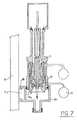
- the closure device constituted by the harness 23 and / or the valve 15, includes means ensuring the actuation of the valves 15 and 12 to determine the closing of the second valve in position. high and the opening of the first valve in order to allow the passage of a washing product coming from a reservoir 28 from the interior zone 101 of the skirt 10, that is to say including the exterior wall of the valve 15 and up to the inner zone 155 of this second valve 15.
- these means are provided on the valve 15 which has for this purpose a finger 156 coming to bear on the harness 23 in order to close the inner seat 153 of the second valve 15 and to open the seat 121 of the first valve 12.
- the washing product from the reservoir 28 after having washed all the lower areas of the head liable to be soiled, is discharged towards the reservoir 7 to be evacuated.
- the harness 23 also includes in its central zone, a small piston 231 pushed by a spring 232, this piston being intended to fade under the action of the cannula 11 placed in the low position during the operation of washing. During the filling operation, this piston 231 returns in the plane of the harness 23 to prevent the accumulation of dirt in this housing of the piston 231.
- the entire lower end of the head is washed by using a housing 29 which fits tightly against the outer wall of the skirt 10.
- this housing is internally provided with a finger 291 capable of lifting the second then the first valve to produce, as in the case of FIG. 6, the closing of the lower seat 153 of the second valve 15 and the opening of the seat 121 of the valve 12 in order to allow the washing product contained in the reservoir 28 to wash the entire lower region of the head and then to be evacuated in the reservoir 7.
- the housing 29 will preferably be positioned, by a dovetail or similar assembly 30, on a support 211 provided, for example, at a determined height on the slide 21.
Landscapes
- Chemical & Material Sciences (AREA)
- Chemical Kinetics & Catalysis (AREA)
- Filling Of Jars Or Cans And Processes For Cleaning And Sealing Jars (AREA)
Applications Claiming Priority (2)
| Application Number | Priority Date | Filing Date | Title |
|---|---|---|---|
| FR9207043A FR2692243A1 (fr) | 1992-06-11 | 1992-06-11 | Installation pour le remplissage de bouteilles par un liquide. |
| FR9207043 | 1992-06-11 |
Publications (1)
| Publication Number | Publication Date |
|---|---|
| EP0574321A1 true EP0574321A1 (de) | 1993-12-15 |
Family
ID=9430625
Family Applications (1)
| Application Number | Title | Priority Date | Filing Date |
|---|---|---|---|
| EP93401490A Withdrawn EP0574321A1 (de) | 1992-06-11 | 1993-06-10 | Anlage zum Abfüllen von Flaschen mit einer Flüssigkeit |
Country Status (2)
| Country | Link |
|---|---|
| EP (1) | EP0574321A1 (de) |
| FR (1) | FR2692243A1 (de) |
Cited By (15)
| Publication number | Priority date | Publication date | Assignee | Title |
|---|---|---|---|---|
| EP0659682A1 (de) * | 1993-12-24 | 1995-06-28 | ORTMANN + HERBST Maschinen- und Anlagenbau GmbH | Getränkefüllmaschine mit CIP-Reinigungsbechern |
| EP0885838A1 (de) * | 1997-06-20 | 1998-12-23 | MBF S.p.A. | Drehtischfüllmaschine zum Abfüllen von Flüssigkeiten in Behälter |
| EP1101998A3 (de) * | 1999-11-16 | 2002-07-17 | Shibuya Kogyo Co., Ltd | Zweistufige Füllungsverfahren mit Druckgas |
| FR2841232A1 (fr) * | 2002-01-30 | 2003-12-26 | Irundin Sl | Bec de remplissage muni d'un systeme d'application de nitrogene et dispositif de rincage automatique pour les embouteilleuses |
| FR2842799A1 (fr) * | 2002-01-30 | 2004-01-30 | Irundin Sl | Dispositif de rincage ameliore pour les becs des embouteilleuses |
| WO2005003018A1 (en) * | 2003-07-03 | 2005-01-13 | Stk Stocchi Progetti Srl | Filling valve for the aseptic filling of alimentary liquids |
| EP1544155A1 (de) * | 2003-12-19 | 2005-06-22 | KHS Maschinen- und Anlagenbau Aktiengesellschaft | Füllelement sowie Füllmaschine mit derartigen Füllelementen |
| FR2911594A1 (fr) * | 2007-01-22 | 2008-07-25 | Sidel Participations | Machine de remplissage equipee d'un dispositif de nettoyage avec membrane deformable |
| ITPD20090116A1 (it) * | 2009-04-30 | 2010-11-01 | Gruppo Bertolaso Spa | Macchina riempitrice e metodo di sanificazione di detta macchina riempitrice |
| DE102010027623A1 (de) | 2010-07-19 | 2012-01-19 | Krones Aktiengesellschaft | Füllvorrichtung für Behältnisse mit Reinigungssystem |
| DE102010027624A1 (de) * | 2010-07-19 | 2012-01-19 | Krones Aktiengesellschaft | Vorrichtung zum Behandeln von Behältnissen mit Spülkappe |
| EP2493805A1 (de) * | 2009-10-29 | 2012-09-05 | KHS GmbH | Füllelement sowie füllmaschine zum füllen von behältern |
| US8261783B2 (en) | 2007-01-22 | 2012-09-11 | Sidel Participations | Filling machine provided with a cleaning device |
| US8291945B2 (en) | 2006-03-31 | 2012-10-23 | Sidel Participations | Cleaning device for filling a machine |
| CN105621333A (zh) * | 2014-11-25 | 2016-06-01 | 克罗内斯股份公司 | 用于在容器处理设备中抬升和降低容器的升降单元 |
Citations (4)
| Publication number | Priority date | Publication date | Assignee | Title |
|---|---|---|---|---|
| FR1595492A (de) * | 1968-12-26 | 1970-06-08 | ||
| DE3325338A1 (de) * | 1983-07-13 | 1985-01-31 | Otto Sick Kg, 7830 Emmendingen | Fuelleinrichtung fuer stillgetraenke |
| EP0341626A1 (de) * | 1988-05-10 | 1989-11-15 | KHS Maschinen- und Anlagenbau Aktiengesellschaft | Verfahren und Vorrichtung zum Abfüllen von flüssigem Füllgut in Flaschen |
| US4938261A (en) * | 1988-08-08 | 1990-07-03 | H & K Inc. | Apparatus for filling cans with a liquid |
-
1992
- 1992-06-11 FR FR9207043A patent/FR2692243A1/fr not_active Withdrawn
-
1993
- 1993-06-10 EP EP93401490A patent/EP0574321A1/de not_active Withdrawn
Patent Citations (4)
| Publication number | Priority date | Publication date | Assignee | Title |
|---|---|---|---|---|
| FR1595492A (de) * | 1968-12-26 | 1970-06-08 | ||
| DE3325338A1 (de) * | 1983-07-13 | 1985-01-31 | Otto Sick Kg, 7830 Emmendingen | Fuelleinrichtung fuer stillgetraenke |
| EP0341626A1 (de) * | 1988-05-10 | 1989-11-15 | KHS Maschinen- und Anlagenbau Aktiengesellschaft | Verfahren und Vorrichtung zum Abfüllen von flüssigem Füllgut in Flaschen |
| US4938261A (en) * | 1988-08-08 | 1990-07-03 | H & K Inc. | Apparatus for filling cans with a liquid |
Cited By (31)
| Publication number | Priority date | Publication date | Assignee | Title |
|---|---|---|---|---|
| EP0659682A1 (de) * | 1993-12-24 | 1995-06-28 | ORTMANN + HERBST Maschinen- und Anlagenbau GmbH | Getränkefüllmaschine mit CIP-Reinigungsbechern |
| EP0885838A1 (de) * | 1997-06-20 | 1998-12-23 | MBF S.p.A. | Drehtischfüllmaschine zum Abfüllen von Flüssigkeiten in Behälter |
| EP0962420A3 (de) * | 1997-06-20 | 2000-04-05 | MBF S.p.A. | Drehtischfüllmaschine zum Abfüllen von Flüssigkeiten in Behälter |
| EP1101998A3 (de) * | 1999-11-16 | 2002-07-17 | Shibuya Kogyo Co., Ltd | Zweistufige Füllungsverfahren mit Druckgas |
| ES2216665A1 (es) * | 2002-01-30 | 2004-10-16 | Irundin, S.L. | Caño de llenado con sistema de aplicacion de nitrogeno y dispositivo de limpieza automatico para maquinas embotelladoras. |
| FR2842799A1 (fr) * | 2002-01-30 | 2004-01-30 | Irundin Sl | Dispositif de rincage ameliore pour les becs des embouteilleuses |
| ES2216665B1 (es) * | 2002-01-30 | 2006-02-16 | Irundin, S.L. | Caño de llenado con sistema de aplicacion de nitrogeno y dispositivo de limpieza automatico para maquinas embotelladoras. |
| FR2841232A1 (fr) * | 2002-01-30 | 2003-12-26 | Irundin Sl | Bec de remplissage muni d'un systeme d'application de nitrogene et dispositif de rincage automatique pour les embouteilleuses |
| US7571749B2 (en) | 2003-07-03 | 2009-08-11 | Stk Stocchi Progetti Srl | Filling valve for the aseptic filling of alimentary liquids |
| WO2005003018A1 (en) * | 2003-07-03 | 2005-01-13 | Stk Stocchi Progetti Srl | Filling valve for the aseptic filling of alimentary liquids |
| EP1688387A3 (de) * | 2003-07-03 | 2006-08-16 | STK Stocchi Progetti Srl | Füllventil zur aseptischen Abfüllung von flüssigen Nahrungsmitteln |
| EP1544155A1 (de) * | 2003-12-19 | 2005-06-22 | KHS Maschinen- und Anlagenbau Aktiengesellschaft | Füllelement sowie Füllmaschine mit derartigen Füllelementen |
| JP2005178907A (ja) * | 2003-12-19 | 2005-07-07 | Khs Mas & Anlagenbau Ag | 充填部材、並びにこの様式の充填部材を有する充填機械 |
| US7104033B2 (en) | 2003-12-19 | 2006-09-12 | Khs Maschinen-Und Anlagenbau Ag | Beverage bottling plant for filling bottles with a liquid beverage, having a filling element and filling machine with such filling elements |
| US8291945B2 (en) | 2006-03-31 | 2012-10-23 | Sidel Participations | Cleaning device for filling a machine |
| WO2008107539A1 (fr) * | 2007-01-22 | 2008-09-12 | Sidel Participations | Machine de remplissage équipée d'un dispositif de nettoyage avec membrane deformable |
| US8261783B2 (en) | 2007-01-22 | 2012-09-11 | Sidel Participations | Filling machine provided with a cleaning device |
| US8387668B2 (en) | 2007-01-22 | 2013-03-05 | Sidel Participations | Filling machine provided with a cleaning device with a deformable membrane |
| FR2911594A1 (fr) * | 2007-01-22 | 2008-07-25 | Sidel Participations | Machine de remplissage equipee d'un dispositif de nettoyage avec membrane deformable |
| CN101626973B (zh) * | 2007-01-22 | 2011-08-10 | 西德尔合作公司 | 设置有具有可变形隔膜的清洁装置的填充机器 |
| JP2010516442A (ja) * | 2007-01-22 | 2010-05-20 | シデル パルティシパション | 可変形薄膜を有する洗浄器を備えた充填装置 |
| EP2246291A1 (de) * | 2009-04-30 | 2010-11-03 | Gruppo Bertolaso S.p.A. | Füllmaschine und Verfahren zur Desinfektion der Füllmaschine |
| ITPD20090116A1 (it) * | 2009-04-30 | 2010-11-01 | Gruppo Bertolaso Spa | Macchina riempitrice e metodo di sanificazione di detta macchina riempitrice |
| EP2493805A1 (de) * | 2009-10-29 | 2012-09-05 | KHS GmbH | Füllelement sowie füllmaschine zum füllen von behältern |
| DE102010027624A1 (de) * | 2010-07-19 | 2012-01-19 | Krones Aktiengesellschaft | Vorrichtung zum Behandeln von Behältnissen mit Spülkappe |
| EP2409947A2 (de) | 2010-07-19 | 2012-01-25 | Krones AG | Füllvorrichtung für Behältnisse mit Reinigungssystem |
| CN102372240A (zh) * | 2010-07-19 | 2012-03-14 | 克朗斯股份有限公司 | 具有冲洗盖的容器处理设备 |
| DE102010027623A1 (de) | 2010-07-19 | 2012-01-19 | Krones Aktiengesellschaft | Füllvorrichtung für Behältnisse mit Reinigungssystem |
| CN102372240B (zh) * | 2010-07-19 | 2014-07-23 | 克朗斯股份有限公司 | 具有冲洗盖的容器处理设备 |
| CN105621333A (zh) * | 2014-11-25 | 2016-06-01 | 克罗内斯股份公司 | 用于在容器处理设备中抬升和降低容器的升降单元 |
| CN105621333B (zh) * | 2014-11-25 | 2019-04-12 | 克罗内斯股份公司 | 用于在容器处理设备中抬升和降低容器的升降单元 |
Also Published As
| Publication number | Publication date |
|---|---|
| FR2692243A1 (fr) | 1993-12-17 |
Similar Documents
| Publication | Publication Date | Title |
|---|---|---|
| WO2007096321A1 (fr) | Vanne a debit variable d'une remplisseuse | |
| FR2692243A1 (fr) | Installation pour le remplissage de bouteilles par un liquide. | |
| EP0597161B1 (de) | Kombinierte Vorrichtung zum Abziehen von Flüssigkeit und Reinigungsgerät dafür | |
| FR2662194A1 (fr) | Mecanisme de chasse interrompable, a ecoulement minimal assure. | |
| FR2560587A1 (fr) | Dispositif d'accrochage d'un recipient a une valve de remplissage, notamment pour des machines automatiques de type continu destinees a remplir de liquide des bouteilles | |
| FR2765661A1 (fr) | Appareil et vanne cryogenique pour la fourniture d'un liquide cryogenique, et installation correspondante de conditionnement d'un produit | |
| FR2492798A1 (fr) | Dispositif de rincage, comportant des recipients de rincage, pour le nettoyage microbiologique des parties de machines de remplissage par lesquelles passe un liquide | |
| EP0591043B1 (de) | Mit Druckgas wiederfüllbarer Aerosolverpackungsbehälter | |
| EP0235063A1 (de) | Zapfhahn für unter Druck stehende Getränke, insbesondere kohlensäurehaltige Getränke, wie Bier, mit einer gewünschten Schaumkrone | |
| FR2493291A1 (fr) | Dispositif de remplissage automatique de bouteilles et installation en comportant application | |
| FR2677007A1 (fr) | Bec de soutirage, machine de soutirage equipee de ce bec et procede de mise en óoeuvre de ce bec. | |
| FR2498581A1 (fr) | Tire-bouchon | |
| EP0285472B1 (de) | Dosierkopf für unter Druck stehende Behälter mit kontinuierlichem Ventil | |
| FR2552749A1 (fr) | Dispositif de remplissage automatique de bouteilles, notamment par des liquides carbonates | |
| EP1084764B1 (de) | Abgabevorrichtung für einen Behälter | |
| CH653968A5 (fr) | Dispositif de fermeture d'un recipient avec un bec verseur encastrable. | |
| FR2607028A1 (fr) | Bol centrifuge | |
| FR2470085A1 (fr) | Element de remplissage pour une machine a contre-pression de remplissage de recipients | |
| FR2658219A1 (fr) | Mecanisme de chasse a commande par bouton-poussoir et a action controlable. | |
| EP0381576B1 (de) | Ablaufstöpsel für sanitäre Einrichtungen | |
| FR2741808A1 (fr) | Pompe de perfusion de liquides medicaux | |
| FR2678300A1 (fr) | Chasse d'eau a deux niveaux de remplissage. | |
| EP0906889B1 (de) | Flaschenfüllvorrichtung mit Füllhöheregelung ohne Flüssigkeitsverlust | |
| FR2525582A1 (fr) | Installation de soutirage | |
| CA2338169A1 (fr) | Dispositif de distribution, notamment pour doseur de machine de remplissage, et doseur equipe d'un tel dispositif |
Legal Events
| Date | Code | Title | Description |
|---|---|---|---|
| PUAI | Public reference made under article 153(3) epc to a published international application that has entered the european phase |
Free format text: ORIGINAL CODE: 0009012 |
|
| AK | Designated contracting states |
Kind code of ref document: A1 Designated state(s): ES GB GR IT |
|
| STAA | Information on the status of an ep patent application or granted ep patent |
Free format text: STATUS: THE APPLICATION IS DEEMED TO BE WITHDRAWN |
|
| 18D | Application deemed to be withdrawn |
Effective date: 19940616 |