EP0574372A1 - Toilettengarnitur - Google Patents
Toilettengarnitur Download PDFInfo
- Publication number
- EP0574372A1 EP0574372A1 EP93870101A EP93870101A EP0574372A1 EP 0574372 A1 EP0574372 A1 EP 0574372A1 EP 93870101 A EP93870101 A EP 93870101A EP 93870101 A EP93870101 A EP 93870101A EP 0574372 A1 EP0574372 A1 EP 0574372A1
- Authority
- EP
- European Patent Office
- Prior art keywords
- valve
- water
- soap
- control
- signal
- Prior art date
- Legal status (The legal status is an assumption and is not a legal conclusion. Google has not performed a legal analysis and makes no representation as to the accuracy of the status listed.)
- Granted
Links
- XLYOFNOQVPJJNP-UHFFFAOYSA-N water Substances O XLYOFNOQVPJJNP-UHFFFAOYSA-N 0.000 claims abstract description 83
- 239000000344 soap Substances 0.000 claims abstract description 58
- 238000012360 testing method Methods 0.000 description 8
- 238000010586 diagram Methods 0.000 description 5
- 238000001514 detection method Methods 0.000 description 4
- 239000007921 spray Substances 0.000 description 2
- 238000004891 communication Methods 0.000 description 1
- 150000001875 compounds Chemical class 0.000 description 1
- 230000001419 dependent effect Effects 0.000 description 1
- 230000009977 dual effect Effects 0.000 description 1
- 230000008030 elimination Effects 0.000 description 1
- 238000003379 elimination reaction Methods 0.000 description 1
- 238000009434 installation Methods 0.000 description 1
- 238000000034 method Methods 0.000 description 1
- 238000012986 modification Methods 0.000 description 1
- 230000004048 modification Effects 0.000 description 1
- 238000009423 ventilation Methods 0.000 description 1
Images


Classifications
-
- E—FIXED CONSTRUCTIONS
- E03—WATER SUPPLY; SEWERAGE
- E03C—DOMESTIC PLUMBING INSTALLATIONS FOR FRESH WATER OR WASTE WATER; SINKS
- E03C1/00—Domestic plumbing installations for fresh water or waste water; Sinks
- E03C1/02—Plumbing installations for fresh water
- E03C1/05—Arrangements of devices on wash-basins, baths, sinks, or the like for remote control of taps
- E03C1/055—Electrical control devices, e.g. with push buttons, control panels or the like
- E03C1/057—Electrical control devices, e.g. with push buttons, control panels or the like touchless, i.e. using sensors
-
- Y—GENERAL TAGGING OF NEW TECHNOLOGICAL DEVELOPMENTS; GENERAL TAGGING OF CROSS-SECTIONAL TECHNOLOGIES SPANNING OVER SEVERAL SECTIONS OF THE IPC; TECHNICAL SUBJECTS COVERED BY FORMER USPC CROSS-REFERENCE ART COLLECTIONS [XRACs] AND DIGESTS
- Y10—TECHNICAL SUBJECTS COVERED BY FORMER USPC
- Y10T—TECHNICAL SUBJECTS COVERED BY FORMER US CLASSIFICATION
- Y10T137/00—Fluid handling
- Y10T137/0318—Processes
-
- Y—GENERAL TAGGING OF NEW TECHNOLOGICAL DEVELOPMENTS; GENERAL TAGGING OF CROSS-SECTIONAL TECHNOLOGIES SPANNING OVER SEVERAL SECTIONS OF THE IPC; TECHNICAL SUBJECTS COVERED BY FORMER USPC CROSS-REFERENCE ART COLLECTIONS [XRACs] AND DIGESTS
- Y10—TECHNICAL SUBJECTS COVERED BY FORMER USPC
- Y10T—TECHNICAL SUBJECTS COVERED BY FORMER US CLASSIFICATION
- Y10T137/00—Fluid handling
- Y10T137/8593—Systems
- Y10T137/86389—Programmer or timer
Definitions
- the invention relates to a washroom fixture comprising :
- a drawback of the known washroom fixture is that there is no communication between the soap dispenser and the other fixtures, such as for example the water faucets. This imposes, on the one hand, the presence of a sensor and a control unit for each of the fixtures, which is a costly solution and, on the other hand, imposes the user to activate each of the sensors individually which is a cumbersome handling.
- a washroom fixture is therefore characterized in that said control unit is further provided for generating a second control signal upon receipt of said presence signal and for transmitting said second control signal to at least one water valve provided for being operative for a second predetermined time period upon receipt of said second control signal.
- the same sensor and the same control unit now controls also the water valve. This signifies that the user has to activate only one sensor in order to operate as well the soap as the water supply.
- the washroom fixture therefore offers not only a comfortable solution to the user but also provides a cheaper and more reliable fixture by reducing the amount of compounds.
- a preferred embodiment of a device according to the present invention is characterized in that said control unit is provided with delay means for delaying the generation of said second control signal over said first time period after generation of said first control signal.
- the water now only starts to flow after soap has been dispensed, so that the water consumption can be reduced by reducing the second time period with increasing comfort.
- a second preferred embodiment of a device is characterized in that said sensor is provided for sensing a continuous presence of the user and for generating a continued presence signal upon detecting said continuous presence, said control unit being provided for generating a third control signal upon receipt of said continuous presence signal after lapse of said first and second time period, said water valve being provided for being operative for a third predetermined time period upon receipt of said third control signal. This enables to continue the water supply for another time period if more water is required.
- a third preferred embodiment of the invention is characterized in that said control unit is provided for generating a fourth control signal after having generated said second control signal and after lapse of said second time period, said washroom fixture further comprising a hand dryer provided for being operative upon receipt of said fourth control signal during a fourth predetermined time period.
- the hand dryer is thus also controlled by the same sensor and the same control unit.
- control unit is being provided with further delay means for delaying the generation of said fourth control signal over said fourth time period signal upon generation of said third control signal. Synchronisation of the hand dryer and water supply is thus provided if more water is needed.
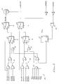
- Fig. 1 is a block diagram illustrating the control system of the present invention.
- Fig. 2A is a circuit diagram of an analog amplifier circuit for receiving and amplifying a signal produced by an infrared motion sensor in response to nearby motion of a user's hands.
- Fig. 2B is a block diagram illustrating connections of DIP switches to a control chip used in the system of the present invention and also indicating the input signals and output signals of the control chips.
- Fig. 2C is a circuit diagram of a reference voltage generating circuit used in the system of Figs. 2A and 2B.
- Figs. 3A and 3B are flowcharts of functions performed by the control chip in Fig. 2B.
- Fig. 4 is a logic diagram of a circuit which controls a valve in response to either a single sensor output signal or a plurality of sensor output signals.
- washroom fixture control system 10 includes an integrated circuit control chip 11 that includes a state machine, the states of which are set forth according to Table 1.
- the state machine and associated logic circuitry which can be effectively implemented in conventional CMOS logic circuitry in control chip 11, performs the functions set forth in the flowcharts of Figs. 3A and 3B.
- Control chip 11 has inputs that receives five water valve output signals SENSW1...SENSW5 which detect the presence of a user's hands adjacent to infrared sensors 13-1, 13-2...13-5, respectively, beneath corresponding water faucet or fountain nozzles. Control chip 11 also has inputs that receive the five soap valve output signals SENSZ1...SENSZ5 produced in response to presence of a user's hands adjacent to infrared sensors located adjacent to corresponding soap dispenser valves. The signals SENSW1...SENSW5 are produced by amplifier/filter circuits 14-1...14-5, respectively. The outputs of infrared sensors 13-1...13-5 are applied to inputs of amplifier/filter circuits 14-1...14-5, respectively. Similarly, the outputs of infrared sensors 33-1...33-5 are connected to inputs of amplifier/filter circuits 34-1...34-5, respectively, to produce the SENSZ1...SENSZ5 signals.
- SENSW1...SENSW5 which detect the presence of a user's hands adjacent to infrared sensors 13-1
- Sensors 13-1...13-5 are positioned to control individual water valves of a wash basin, wash fountain, or the like in response to movement or presence of a person's hand close to water valves.
- infrared sensors 33-1...33-5 are positioned to control individual soap valves of soap dispensers in response to movement or presence of a person's hand close to the soap valves.
- Integrated circuit chip 11 has various outputs 102 and 103 (Fig. 2B) connected to power drivers in block 15 (Fig. 1).
- the outputs 102 include water valve open (i.e., on) signals KWON1, KWON2...KWON5 and water valve closed (i.e., off) signals KWOFF1...KWOFF5.
- the soap valve control outputs 103 include soap valve on (i.e., open) signals KZON1...KZON5 and soap valve off (i.e., closed) signals KZOFF1...KZOFF5.
- the power driver circuitry 15 drives a 4 kilohertz buzzer 16-1 and a 2 kilohertz buzzer 16-2.
- Power driver circuitry 15 also supplies signal 17 to control a hand dryer or towel dispenser 17, five water valve “on” and five water valve “off” signals to five water valves 19-1...19-5, and five soap valve “on” and five soap valve “off” signals to five soap valves 35-1...35-5.
- a battery pack (not shown) powers a circuit producing a power-reset signal and a V DD supply voltage to control chip 11.
- Control chip 11 and the various water solenoid valves and soap solenoid valves can be powered by a battery pack, for example, one containing 3 D-type dry cells.
- control chip 10 in conjunction with the various sensors connected to it, shown in detail in Fig. 2A, has a higher threshold value of STLEV, to initially detect suitable motion of a user's hands to start the fixture control process, than a lower threshold value of WKLEV to detect "continued presence" of the user's hands in order to continue control of the water and soap valves.
- the higher initial threshold prevents undesired opening of water valves or soap valves due to possible external influences, such as a gust of warm air.
- an exemplary amplifier and bandpass circuit for producing the signal SENS in response to the output of infrared sensor 112.
- the signal SENS is an AC signal, which varies between 0 and 4 volts.
- Infrared motion detector 112 can be an RPW100 dual element pyro-electric infrared sensor, available from Philips.
- Amplifiers 113 and 114 can be TLC27L2CD amplifiers, commercially available from Texas Instruments.
- a 2 volt reference voltage V REF is generated by the circuit of Fig. 2C.
- the implementation of this circuit is conventional, and therefore is not described in detail, except to mention that the integrated circuit shown in Fig. 2C is an ICL76635CBA voltage regulator circuit.
- control chip 11 The above-mentioned thresholds are converted by control chip 11 to analog signal levels which are compared by conventional comparators to the various SENS(W i ) and SENS(Z i ) signals produced by the various sensor amplifier circuits to detect amounts of user motion needed to initiate or maintain operation of the water valves and soap valves.
- the presence of a user whose hands are moving into position to use a washroom fixture is definitely established by 32 readings of the AC signal SENS, including 16 readings below low STLEV (for example, 0.5 volts) and 16 readings above high STLEV (for example, 3.5 volts) these two upper and lower “start threshold levels" being centered about the two volt V REF line.
- the corresponding "working threshold levels" against which SENS is compared are 16 readings below low WKLEV (for example, 1.0 volts) and 16 readings above high WKLEV (for example, 3.0 volts).
- Both the initial “start thresholds” and the “working thresholds” can be established by setting the STZ0 and STZ1 DIP switches (i.e., initialization switches), the STW0 and the STW1 DIP switches, and the WKO and WK1 DIP switches in block 109 of Fig. 2B in accordance with Table 2.
- the OM1 and OM2 initialization switch inputs from block 107 of Fig. 2B allow the installer to set the desired delay to be 15, 20, 25, or 30 seconds for the maximum time for a water valve to be open in response to a particular sensor.
- a "variable length" water flow cycle (which-is established by the X2 DIP switch setting of "0") is initiated by detection of the suitable movement of a hand close to the appropriate infrared sensor.
- the length of such a water flow cycle up to a maximum established by the OM1 and OM2 DIP switch settings, is determined by repeated sensing at the above-mentioned "working threshold” levels to detect continued presence (for example, even the slightest motion of the user's hands) near the appropriate infrared sensor.
- a fixed, rather than variable, length water flow cycle established by the X2 DIP switch being set to a "1" opens a water valve for a certain number of seconds established by the DIP switches OM1 and OM2, regardless of the presence or absence of a user's hands in the proximity of the infrared motion sensor.
- control chip 11 effectuates different cycles of soap valve control and water valve control, depending upon whether (1) two infrared sensors are positioned at the faucet and the soap dispenser, respectively, (2) only one sensor is utilized and it is located at the faucet, (3) only one sensor is utilized and it is located at the soap dispenser, or (4) only one sensor is located between the water nozzle and the soap outlet when the water nozzle and soap outlet are located close together.
- the washroom fixture control system described herein therefore is versatile, in that the same system can be installed to operate several different arrangements of water valves and/or soap valve or urinal valves, depending on how the X1, X2, X3, and X4 DIP switches are set and depending on the foregoing positions of the sensors. Table 3 lists the functions of the latter DIP switch settings.
- the X1, X2, X3, and X4 initialization switches control which of the above control cycles are to be utilized for the particular installation desired, in accordance with the following.
- the flowchart shows the sequence of operations and decisions performed by logic elements in control chip 11 to control the multiple (e.g., 5) water valves.
- decision block 41 the value of the present water sensor signal level SENS(Wi) is tested 16 times to determine if its maximum value is above the presently selected upper value of STLEV, (present Start Level of threshold) which, for example, is +3.5 volts, and 16 times to determine if its minimum value is below the selected lower value of STLEV, which is 0.5 volts.
- STLEV Present Start Level of threshold
- a negative determination by decision block 41 means that there is insufficient hand motion near enough to the present water sensor to unambiguously establish the presence of a user that wants to turn on the water, so the testing of SENS(Wi) continues, 32 times per second.
- decision block 42 in which the battery voltage is tested to determine if it is less than 6.3 volts, the level at which insufficient energy remains in the battery to reliably turn the present water valve Wi off. If this is the case, buzzer 16-1 of Fig. 1 is activated to produce a 4 hertz sound for 6 seconds.
- the circuitry of control chip 11 then continues to perform the testing of decision block 41.
- an external hand dryer which can be an electric blow dryer, towel dispenser or the like.
- control chip 11 determines, according to decision block 57, whether further delay is needed, and if so, five seconds is to be added to the delay of block 55 in accordance with block 58 before turning off the present water valve. If the soap sensor has been activated first, it may be desirable to keep the water flowing for 10 seconds, rather than 5 seconds, to allow the user time to soap his or her hands and before putting his or her hands under the faucet. Control chip 11 then tests the X2 initialization switch bit to determine if the water control cycle is of fixed or variable duration. If it is fixed, the circuitry determines if the maximum time (e.g., 20 seconds) set by DIP switches OM1 and OM2 has expired, and if it has not, the flowchart re-enters decision block 59.
- the maximum time e.g. 20 seconds
- the circuitry compares SENS(Wi) to the maximum and minimum WKLEV (Working Level threshold) values selected by the WK0 and WK1 DIP switches. If the continued presence of hands of a user is not thereby detected for 32 successive times, the logic circuitry of control chip 11 turns off the present water valve Wi, but otherwise determines if the maximum water flow time period has elapsed according to decision block 61. If that is the case, control chip 11 turns off the present water valve Wi, but otherwise re-enters the loop beginning with decision block 59. If a wash fountain is being used, as indicated in block 64, an additional two second delay is introduced before beginning the next water flow control cycle, as indicated in block 65.
- SENS(Wi) to the maximum and minimum WKLEV (Working Level threshold) values selected by the WK0 and WK1 DIP switches. If the continued presence of hands of a user is not thereby detected for 32 successive times, the logic circuitry of control chip 11 turns off the present water valve Wi, but otherwise determines if the maximum water
- the logic circuitry of chip 11 tests the present soap sensor amplifier output level and compares it with the corresponding value of STLEV programmed in by means of DIP switches STZ0 and STZ1.
- the logic circuitry of control chip 11 then, in accordance with blocks 72, 73, 74, and 75, tests the battery in the manner previously described in Fig. 3A.
- the logic circuitry waits until the water valve has been turned off, as indicated in block 92, and then introduces 2 more seconds of delay, as indicated in block 93, before beginning the next "soap cycle".
- the resulting fixture control cycle must be a fixed length cycle. This is necessary because when the user then moves his hand under the faucet, a variable cycle of the soap sensor would detect non-presence of the user's hand, and then turn the water flow off, which of course would be unacceptable.
- the above embodiment of the invention has the capability of either (1) allowing any of a plurality of sensors to effectuate "collective" control of a number of fixtures such as faucet valves, or urinal valves, or (2) allowing "individual" control of each fixture by a single corresponding sensor, i.e., for example, each wash station, urinal, or soap dispenser is controlled according to its individual corresponding sensors.
- a single corresponding sensor i.e., for example, each wash station, urinal, or soap dispenser is controlled according to its individual corresponding sensors.
- 5 sensors control a single water valve which supplies water to a single "spray ring" with many spray water nozzles or several separate water nozzles.
- the five sensors are located around the wash fountain.
- Individual soap dispensers, each with its own associated infrared sensor may be located adjacent to each of the five water nozzles.
- control chip 11 contains the above-described logic circuitry for each water valve and each soap valve, respectively, to be controlled. That is, each valve can be independently controlled by its own dedicated logic circuitry.
- a single control chip 11 is the only one required.
- a WV10N (Water Valve 1 On) signal (which also is applied to one of the inputs of OR gate circuit 21) produces direct "individual" control of water valve 25 through multiplexor circuit 24 if multiplexer circuit 24 is set by DIP switch X1 being set to "0" so that its A input is connected to the control input of solenoid valve 25.
- the B input of multiplexer circuit 24 is selected by X1 being set to "1", and any of the five water valve signals WV10N ⁇ ... WV50N ⁇ is applied to the OR gate structure 21.
- the circuitry including OR gate circuit 21 and AND gate 22 checks to determine if solenoid valve 25 is already on, and if it is, then no pulse is applied to turn valve 25 on.
- the inputs to AND gate 33 which actually functions as an OR gate because "negative logic" is being used, establish the timing of the five different sensors used in the collective configuration.
- the signals T ON1 ⁇ , T ON2 ⁇ ... T ON5 ⁇ represent the values of the above-described timers for the 5 water valve ports of control chip 11, respectively. Each of these timer signals is reset to a "0" immediately after sensing the presence of a user. A logical "1" applied to the "on” input of solenoid valve 25 opens it. A logical "1" applied to the "off” input of solenoid valve 25 closes it.
- the circuitry including AND gate 33 and OR gate 32 produces a "1" at the lower input of AND gate 22 if solenoid valve 25 is closed, permitting a "1" output by OR gate circuitry 21 to gate a "1" to the on input of solenoid valve 25, opening it.
- the timer controls how long the water solenoid valve is on, for example 20 seconds. The timer is reset each time any of the sensors in the "collective" configuration indicates the presence of a user. Therefore, as long as a user is present at any of the 5 sensors, water valve 25 remains on and cannot be turned off by any of the WV10FF, WV20FF,...WV50FF signals. As long as any one of the five T ON1 ⁇ , T ON2 ⁇ ...
- T ON5 ⁇ values is a "0"
- no additional turn on pulses can be applied to valve 25 until after it is turned off in one of the ways described earlier. For example, if control chip 11 produces a WVON3 signal equal to a "1" the corresponding timer signal T ON3 ⁇ is immediately set to a "0". Therefore, the left input of OR gate 32 is a "0". The right input of OR gate 32 is a “1” indicating that valve 25 is closed. The lower input of AND gate 22 is a "1", allowing valve 22 to be opened only if it is presently closed. When valve 25 is opened, flip-flop 31 produces a "0" at the right input of OR gate 32.
- valve 25 cannot be opened again because a "0" is produced at the lower input of AND gate 22. Only when valve 25 is closed can flip-flop 31 produce a "1" at the input of AND gate 22 enabling any of the input to OR circuitry 21 to open valve 25.
- valve 25 is successfully turned off by a signal at the output of multiplexor 29, the necessary state is stored in flip-flop 31 to produce a "1" on the right input of OR gate 32 and the lower input of AND gate 22 indicating that valve 25 is closed.
- AND gate 27 prevents any of the WV10FF, WV20FF. .. WV50FF signals from closing valve 25 if the presence of a user is detected at any of the other sensors because its timer signal produces a "0" at an input of AND gate 33, producing a "0" at one input of AND gate 27, disabling the output of OR circuit 26 from reaching the B input of multiplexor 29.
- control chip 11 can be adapted to control lights, security systems, air exhaust systems, toilet seat cover dispensing, ventilation, and other functions.
- control chip 11 can be implemented by a conventional microprocessor or microcomputer programmed to perform the functions of the flowchart of Figs. 3A and 3B, rather than by a logic circuit configured to perform the functions defined by the state table of Table 1.
- the system can, of course, be powered by an inexpensive power supply instead of a battery pack if AC line voltage is readily available.
Landscapes
- Health & Medical Sciences (AREA)
- Life Sciences & Earth Sciences (AREA)
- Engineering & Computer Science (AREA)
- Hydrology & Water Resources (AREA)
- Public Health (AREA)
- Water Supply & Treatment (AREA)
- Domestic Plumbing Installations (AREA)
- Sanitary Device For Flush Toilet (AREA)
- Toilet Supplies (AREA)
Applications Claiming Priority (2)
| Application Number | Priority Date | Filing Date | Title |
|---|---|---|---|
| US07/895,911 US5217035A (en) | 1992-06-09 | 1992-06-09 | System for automatic control of public washroom fixtures |
| US895911 | 1992-06-09 |
Publications (2)
| Publication Number | Publication Date |
|---|---|
| EP0574372A1 true EP0574372A1 (de) | 1993-12-15 |
| EP0574372B1 EP0574372B1 (de) | 1998-08-26 |
Family
ID=25405276
Family Applications (1)
| Application Number | Title | Priority Date | Filing Date |
|---|---|---|---|
| EP93870101A Expired - Lifetime EP0574372B1 (de) | 1992-06-09 | 1993-06-07 | Toilettengarnitur |
Country Status (4)
| Country | Link |
|---|---|
| US (1) | US5217035A (de) |
| EP (1) | EP0574372B1 (de) |
| AT (1) | ATE170248T1 (de) |
| DE (1) | DE69320549T2 (de) |
Cited By (9)
| Publication number | Priority date | Publication date | Assignee | Title |
|---|---|---|---|---|
| EP0792971A1 (de) | 1996-02-28 | 1997-09-03 | N.V. INTERNATIONAL SANITARY WARE-MANUFACTURING CY, S.A. in verkort: N.V. INTERSAN S.A. | Vorrichtung zum Steuern einer Gruppe von Badezimmergeräten |
| EP0830648A4 (de) * | 1995-06-07 | 1998-12-16 | Univ Missouri | Druck-/vakuumregler |
| WO1999033008A3 (en) * | 1997-12-23 | 1999-11-11 | Kimberly Clark Co | System and method for collecting data on product consumption |
| US6027200A (en) * | 1993-01-29 | 2000-02-22 | Canon Kabushiki Kaisha | Information processing apparatus having means for estimating expendables to be consumed during recording |
| WO2000012830A1 (en) * | 1998-08-26 | 2000-03-09 | Eco-Logic (Uk) Emps Limited | Control unit for fluid control valves |
| US6411920B1 (en) | 1999-06-23 | 2002-06-25 | Kimberly-Clark Worldwide, Inc. | System and method for collecting data on product consumption |
| US7213782B2 (en) | 2004-01-30 | 2007-05-08 | Charles Agnew Osborne | Intelligent dispensing system |
| US9756992B2 (en) | 2013-03-15 | 2017-09-12 | Vsi Import Solutions, Llc | Electronic residential tissue dispenser |
| US9907441B2 (en) | 2014-04-18 | 2018-03-06 | Vsi Import Solutions, Llc | Electronic residential tissue dispenser |
Families Citing this family (113)
| Publication number | Priority date | Publication date | Assignee | Title |
|---|---|---|---|---|
| JP2540733Y2 (ja) * | 1991-09-24 | 1997-07-09 | 株式会社イナックス | 水石鹸自動供給装置 |
| GB2304038B (en) * | 1995-08-10 | 1999-04-28 | Hmsi Limited | Handwash station |
| US5533202A (en) * | 1992-11-02 | 1996-07-02 | Zenith Electronics Corporation | Apparatus using a binary coded decimal switch and a programmable logic array for selectively coupling terminals of a controller chip to data bus lines |
| DE4341649A1 (de) * | 1993-12-07 | 1995-06-08 | Grohe Armaturen Friedrich | Selbstschlußventil |
| DE29508850U1 (de) * | 1994-06-13 | 1995-08-17 | Geberit Technik AG, Jona, St.Gallen | Anordnung zur berührungslosen, elektronischen Steuerung des Wasserflusses einer Sanitäranlage |
| US5627375A (en) * | 1994-11-07 | 1997-05-06 | Hsieh; Chin-Hua | Circuit arrangement for a sanitary apparatus |
| US5566702A (en) * | 1994-12-30 | 1996-10-22 | Philipp; Harald | Adaptive faucet controller measuring proximity and motion |
| US5782382A (en) * | 1995-12-27 | 1998-07-21 | International Sanitary Ware Manufacturing Cy | Dispenser for personal hygiene liquids |
| US6695246B1 (en) * | 1996-02-16 | 2004-02-24 | Bay West Paper Corporation | Microprocessor controlled hands-free paper towel dispenser |
| US5772291A (en) * | 1996-02-16 | 1998-06-30 | Mosinee Paper Corporation | Hands-free paper towel dispensers |
| ATE212402T1 (de) * | 1996-02-28 | 2002-02-15 | Internat Sanitary Ware Mfg Cy | Vorrichtung zum steuern einer gruppe von badezimmergeräten |
| US6059192A (en) * | 1996-04-04 | 2000-05-09 | Zosimadis; Peter | Wireless temperature monitoring system |
| US5711329A (en) * | 1996-05-28 | 1998-01-27 | Soon; Min Tet | Self-cleaning knob water faucet |
| AU8404398A (en) | 1997-07-18 | 1999-02-10 | Kohler Company | Advanced touchless plumbing systems |
| US5915417A (en) * | 1997-09-15 | 1999-06-29 | T&S Brass And Bronze Works, Inc. | Automatic fluid flow control apparatus |
| US6038519A (en) * | 1997-12-31 | 2000-03-14 | Sloan Valve Company | Control board for controlling and monitoring usage of water |
| US5966753A (en) * | 1997-12-31 | 1999-10-19 | Sloan Valve Company | Method and apparatus for properly sequenced hand washing |
| US6195588B1 (en) | 1997-12-31 | 2001-02-27 | Sloan Valve Company | Control board for controlling and monitoring usage of water |
| US6293486B1 (en) * | 1998-02-16 | 2001-09-25 | Mosinee Paper Corporation | Hands-free paper towel dispensers |
| US6412679B2 (en) | 1998-05-20 | 2002-07-02 | Georgia-Pacific Corporation | Paper towel dispenser |
| US6202980B1 (en) | 1999-01-15 | 2001-03-20 | Masco Corporation Of Indiana | Electronic faucet |
| US6209751B1 (en) | 1999-09-14 | 2001-04-03 | Woodward Laboratories, Inc. | Fluid dispenser |
| US6279777B1 (en) | 1999-09-14 | 2001-08-28 | Woodward Laboratories, Inc. | Dispensing control system |
| US6390329B1 (en) | 2000-10-10 | 2002-05-21 | Joseph S. Kanfer | Apparatus for hands-free dispensing of a measured quantity of material |
| US6639209B1 (en) | 2000-10-24 | 2003-10-28 | Synpase, Inc. | Method of automatic standardized calibration for infrared sensing device |
| US7376351B2 (en) * | 2000-10-24 | 2008-05-20 | Geberit Technik Ag | Data communications system and method for communication between infrared devices |
| US6955333B2 (en) * | 2000-10-24 | 2005-10-18 | Geberit Technik Ag | Apparatus and method of wireless data transmission |
| US7099649B2 (en) * | 2000-10-24 | 2006-08-29 | Geberit Technik Ag | System and method for wireless data exchange between an appliance and a handheld device |
| US6768103B2 (en) * | 2000-10-24 | 2004-07-27 | The Chicago Faucet Company | System and method of automatic dynamic calibration for infrared sensing device |
| US6770869B2 (en) * | 2000-10-24 | 2004-08-03 | The Chicago Faucet Company | Method of automatic standardized calibration for infrared sensing device |
| US6707030B1 (en) | 2000-10-24 | 2004-03-16 | Synapse, Inc. | System and method of automatic dynamic calibration for infrared sensing device |
| US6956498B1 (en) | 2000-11-02 | 2005-10-18 | Sloan Valve Company | System for remote operation of a personal hygiene or sanitary appliance |
| BR0207029A (pt) | 2001-02-07 | 2004-06-22 | Gerenraich Family Trust | Sistema de controle com detector capacitivo |
| US6592067B2 (en) | 2001-02-09 | 2003-07-15 | Georgia-Pacific Corporation | Minimizing paper waste carousel-style dispenser apparatus, sensor, method and system with proximity sensor |
| US7017856B2 (en) * | 2001-02-09 | 2006-03-28 | Georgia-Pacific Corporation | Static build-up control in dispensing system |
| US7102366B2 (en) * | 2001-02-09 | 2006-09-05 | Georgia-Pacific Corporation | Proximity detection circuit and method of detecting capacitance changes |
| US7597122B1 (en) | 2001-07-26 | 2009-10-06 | Smith Judson L | Apparatus and method to monitor the usage of a network system of personal hand sanitizing dispensers |
| US6883563B2 (en) | 2001-07-26 | 2005-04-26 | Judson L. Smith | Apparatus and method to monitor the usage of a network system of personal hand sanitizing dispensers |
| WO2003038537A1 (en) * | 2001-11-01 | 2003-05-08 | The Chicago Faucet Company | Apparatus for controlling fluid flow and temperature |
| US6860288B2 (en) * | 2001-12-21 | 2005-03-01 | Kenneth J. Uhler | System and method for monitoring and controlling utility systems |
| US7341170B2 (en) * | 2002-03-07 | 2008-03-11 | Georgia-Pacific Consumer Operations Llc | Apparatus and methods usable in connection with dispensing flexible sheet material from a roll |
| US7665673B2 (en) * | 2002-04-19 | 2010-02-23 | Hagleitner Hygiene International Gmbh | Method and apparatus for spraying portions of an air-improving substance |
| CA2390411A1 (en) * | 2002-06-03 | 2003-12-03 | Alwin Manufacturing Company, Incorporated | Automatic dispenser apparatus |
| US6977588B2 (en) * | 2002-06-03 | 2005-12-20 | Alwin Manufacturing Co. | Automatic dispenser apparatus |
| US7351977B2 (en) * | 2002-11-08 | 2008-04-01 | L-3 Communications Cincinnati Electronics Corporation | Methods and systems for distinguishing multiple wavelengths of radiation and increasing detected signals in a detection system using micro-optic structures |
| ATE508093T1 (de) | 2003-03-21 | 2011-05-15 | Kanfer Joseph S | Vorrichtung zur handfreien abgabe einer dosierten materialmenge |
| US6967587B2 (en) * | 2003-09-22 | 2005-11-22 | Sanidoor, Llc | Hands-free door opener and method |
| US6988689B2 (en) * | 2003-10-10 | 2006-01-24 | Bay West Paper Corporation | Hands-free towel dispenser with EMF controller |
| US7774096B2 (en) | 2003-12-31 | 2010-08-10 | Kimberly-Clark Worldwide, Inc. | Apparatus for dispensing and identifying product in washrooms |
| US7783380B2 (en) | 2003-12-31 | 2010-08-24 | Kimberly-Clark Worldwide, Inc. | System and method for measuring, monitoring and controlling washroom dispensers and products |
| US7690395B2 (en) | 2004-01-12 | 2010-04-06 | Masco Corporation Of Indiana | Multi-mode hands free automatic faucet |
| US7690393B2 (en) * | 2004-03-19 | 2010-04-06 | Flow-Tech Industries, Inc. | Irrigation system external water supply shutoff |
| US7296765B2 (en) * | 2004-11-29 | 2007-11-20 | Alwin Manufacturing Co., Inc. | Automatic dispensers |
| US7516939B2 (en) * | 2004-12-14 | 2009-04-14 | Masco Corporation Of Indiana | Dual detection sensor system for washroom device |
| USD512648S1 (en) | 2004-12-15 | 2005-12-13 | Smith Judson L | Dispenser for fluid material |
| USD522785S1 (en) | 2005-01-31 | 2006-06-13 | James Brady | Towel dispenser |
| US20070000941A1 (en) * | 2005-07-01 | 2007-01-04 | Hadden David M | Motion-activated soap dispenser |
| US20070010389A1 (en) * | 2005-07-01 | 2007-01-11 | Scott Paper Limited | Hands-free towel dispenser |
| WO2007013142A1 (ja) * | 2005-07-26 | 2007-02-01 | Mitsubishi Denki Kabushiki Kaisha | 手乾燥装置 |
| CA2533000C (en) * | 2005-12-08 | 2011-07-05 | Alwin Manufacturing Co., Inc | Method and apparatus for controlling a dispenser and detecting a user |
| US20070194166A1 (en) * | 2006-02-18 | 2007-08-23 | Georgia-Pacific Consumer Products Lp | Electronic Dispenser for Dispensing Sheet Products |
| US8089473B2 (en) | 2006-04-20 | 2012-01-03 | Masco Corporation Of Indiana | Touch sensor |
| US8365767B2 (en) | 2006-04-20 | 2013-02-05 | Masco Corporation Of Indiana | User interface for a faucet |
| US8118240B2 (en) | 2006-04-20 | 2012-02-21 | Masco Corporation Of Indiana | Pull-out wand |
| US9243756B2 (en) | 2006-04-20 | 2016-01-26 | Delta Faucet Company | Capacitive user interface for a faucet and method of forming |
| US8162236B2 (en) | 2006-04-20 | 2012-04-24 | Masco Corporation Of Indiana | Electronic user interface for electronic mixing of water for residential faucets |
| MX2009003903A (es) * | 2006-10-13 | 2009-06-11 | Sloan Valve Co | Fluxometro automatico programable. |
| US7878446B2 (en) | 2006-10-20 | 2011-02-01 | Georgia-Pacific Consumer Products Lp | Dispenser housing with motorized roller transport |
| WO2008051973A1 (en) | 2006-10-24 | 2008-05-02 | Bradley Fixtures Corporation | Capacitive sensing for washroom fixture |
| US8006712B2 (en) * | 2006-10-27 | 2011-08-30 | Kum F Boey | Faucet control system and method |
| US9243392B2 (en) | 2006-12-19 | 2016-01-26 | Delta Faucet Company | Resistive coupling for an automatic faucet |
| US8944105B2 (en) | 2007-01-31 | 2015-02-03 | Masco Corporation Of Indiana | Capacitive sensing apparatus and method for faucets |
| US7806141B2 (en) | 2007-01-31 | 2010-10-05 | Masco Corporation Of Indiana | Mixing valve including a molded waterway assembly |
| CA2675417C (en) | 2007-03-28 | 2015-10-13 | Masco Corporation Of Indiana | Improved capacitive touch sensor |
| GB2467661B (en) | 2007-09-20 | 2013-02-13 | Bradley Fixtures Corp | Lavatory system |
| WO2009075858A1 (en) | 2007-12-11 | 2009-06-18 | Masco Corporation Of Indiana | Capacitive coupling arrangement for a faucet |
| US20090309054A1 (en) * | 2008-06-11 | 2009-12-17 | Automatic Switch Company | System and method of operating a solenoid valve at minimum power levels |
| US20100064426A1 (en) * | 2008-09-12 | 2010-03-18 | Marc Chikara Imamura | Toilet Seat Alarm Handle |
| US20100188229A1 (en) * | 2009-01-26 | 2010-07-29 | Nhean Nhep | Safety shut off system for household appliances |
| DE102009025079A1 (de) * | 2009-06-10 | 2010-12-16 | Dorma Gmbh + Co. Kg | Automatische Sanitäranlage |
| MX2012004000A (es) | 2009-10-07 | 2012-10-05 | Bradley Fixtures Corp | Sistema de lavado con secador para manos. |
| US9032565B2 (en) | 2009-12-16 | 2015-05-19 | Kohler Co. | Touchless faucet assembly and method of operation |
| US8776817B2 (en) | 2010-04-20 | 2014-07-15 | Masco Corporation Of Indiana | Electronic faucet with a capacitive sensing system and a method therefor |
| US8561626B2 (en) | 2010-04-20 | 2013-10-22 | Masco Corporation Of Indiana | Capacitive sensing system and method for operating a faucet |
| US8919233B2 (en) * | 2010-12-30 | 2014-12-30 | Kimberly-Clark Worldwide, Inc. | Electronic pre-cut sheet dispenser with dispensing adjustments |
| US10172498B2 (en) | 2011-04-18 | 2019-01-08 | Bradley Fixtures Corporation | Hand dryer with point of ingress dependent air delay and filter sensor |
| US9170148B2 (en) | 2011-04-18 | 2015-10-27 | Bradley Fixtures Corporation | Soap dispenser having fluid level sensor |
| US10294642B2 (en) | 2011-04-18 | 2019-05-21 | Bradley Fixtures Corporation | Lavatory system with integrated hand dryer |
| US9267736B2 (en) * | 2011-04-18 | 2016-02-23 | Bradley Fixtures Corporation | Hand dryer with point of ingress dependent air delay and filter sensor |
| US20130248033A1 (en) | 2012-03-07 | 2013-09-26 | Moen Incorporated | Electronic plumbing fixture fitting |
| EP2828440B1 (de) | 2012-03-21 | 2018-06-27 | Bradley Fixtures Corporation | Becken und handtrocknungssystem |
| EP2859153A4 (de) | 2012-04-20 | 2016-06-22 | Masco Corp | Wasserhahn mit einem ausziehbaren bügel mit kapazitiver detektion |
| US10100501B2 (en) | 2012-08-24 | 2018-10-16 | Bradley Fixtures Corporation | Multi-purpose hand washing station |
| CA2933411C (en) * | 2013-12-16 | 2021-03-30 | M.I.S. Electronics Inc. | Control system for washroom devices |
| US11015329B2 (en) | 2016-06-08 | 2021-05-25 | Bradley Corporation | Lavatory drain system |
| US10041236B2 (en) | 2016-06-08 | 2018-08-07 | Bradley Corporation | Multi-function fixture for a lavatory system |
| US10373477B1 (en) | 2016-09-28 | 2019-08-06 | Gojo Industries, Inc. | Hygiene compliance modules for dispensers, dispensers and compliance monitoring systems |
| US11299872B2 (en) | 2017-12-29 | 2022-04-12 | Kimberly-Clark Worldwide, Inc. | Washroom monitoring system |
| USD859124S1 (en) | 2018-07-20 | 2019-09-10 | Jimmy Wayne Brooks | Toilet lid accessory handle |
| US12301661B2 (en) | 2019-12-06 | 2025-05-13 | Zurn Water, Llc | Water management system and user interface |
| WO2021252008A1 (en) | 2020-06-08 | 2021-12-16 | Zurn Industries, Llc | Cloud-connected occupancy lights and status indication |
| US11108865B1 (en) | 2020-07-27 | 2021-08-31 | Zurn Industries, Llc | Battery powered end point device for IoT applications |
| US11153945B1 (en) | 2020-12-14 | 2021-10-19 | Zurn Industries, Llc | Facility occupancy detection with thermal grid sensor |
| US11316908B1 (en) | 2021-02-01 | 2022-04-26 | Zurn Industries, Llc | BACnet conversion of water management data for building management solutions |
| US11594119B2 (en) | 2021-05-21 | 2023-02-28 | Zurn Industries, Llc | System and method for providing a connection status of a battery powered end point device |
| US11221601B1 (en) | 2021-05-24 | 2022-01-11 | Zurn Industries, Llc | Various IoT sensory products and cloud-purge for commercial building solutions utilizing LoRa to BACnet conversion for efficient data management and monitoring |
| US11573539B1 (en) | 2021-09-03 | 2023-02-07 | Zurn Industries, Llc | Managing edge devices in building management systems |
| CN113940576B (zh) * | 2021-10-14 | 2023-08-15 | 上海利康消毒高科技有限公司 | 一种红外非接触出液器的出液方法 |
| US11543791B1 (en) | 2022-02-10 | 2023-01-03 | Zurn Industries, Llc | Determining operations for a smart fixture based on an area status |
| US11514679B1 (en) | 2022-02-18 | 2022-11-29 | Zurn Industries, Llc | Smart method for noise rejection in spatial human detection systems for a cloud connected occupancy sensing network |
| US11555734B1 (en) | 2022-02-18 | 2023-01-17 | Zurn Industries, Llc | Smart and cloud connected detection mechanism and real-time internet of things (IoT) system management |
| US12493355B2 (en) | 2022-04-14 | 2025-12-09 | Kohler Co. | Touchless plumbing control system |
| US12599271B2 (en) | 2023-09-18 | 2026-04-14 | Shyamal Chakravorty | Hygienic and controlled fabric web dispensing system |
Citations (3)
| Publication number | Priority date | Publication date | Assignee | Title |
|---|---|---|---|---|
| US4606085A (en) * | 1985-03-27 | 1986-08-19 | Davies Joseph R | Hand washing device |
| DE3938533A1 (de) * | 1989-11-21 | 1991-05-23 | Rainer M Lutz | Wasserauslaufarmatur |
| US5031258A (en) * | 1989-07-12 | 1991-07-16 | Bauer Industries Inc. | Wash station and method of operation |
Family Cites Families (9)
| Publication number | Priority date | Publication date | Assignee | Title |
|---|---|---|---|---|
| US3151340A (en) * | 1961-10-26 | 1964-10-06 | Carousel Sanwa Licensing Corp | Automatic water-supply apparatus |
| US4788998A (en) * | 1981-03-26 | 1988-12-06 | Pepper Robert B | Ultrasonically operated water faucet |
| US4914758A (en) * | 1988-06-27 | 1990-04-10 | Bauer Industries Inc. | Fresh water control system and method |
| US4886207A (en) * | 1988-09-14 | 1989-12-12 | Lee Chang H | Automatic mixing faucet |
| JP2774545B2 (ja) * | 1989-02-07 | 1998-07-09 | 東陶機器株式会社 | 自動水栓装置 |
| US5060323A (en) * | 1989-07-12 | 1991-10-29 | Bauer Industries, Inc. | Modular system for automatic operation of a water faucet |
| US5086526A (en) * | 1989-10-10 | 1992-02-11 | International Sanitary Ware Manufacturin Cy, S.A. | Body heat responsive control apparatus |
| US4941219A (en) * | 1989-10-10 | 1990-07-17 | International Sanitary Ware Manufacturing Cy, S.A. | Body heat responsive valve control apparatus |
| US5095941A (en) * | 1990-06-27 | 1992-03-17 | Betz John J | Method and apparatus for actuating a faucet |
-
1992
- 1992-06-09 US US07/895,911 patent/US5217035A/en not_active Expired - Lifetime
-
1993
- 1993-06-07 EP EP93870101A patent/EP0574372B1/de not_active Expired - Lifetime
- 1993-06-07 AT AT93870101T patent/ATE170248T1/de not_active IP Right Cessation
- 1993-06-07 DE DE69320549T patent/DE69320549T2/de not_active Expired - Lifetime
Patent Citations (3)
| Publication number | Priority date | Publication date | Assignee | Title |
|---|---|---|---|---|
| US4606085A (en) * | 1985-03-27 | 1986-08-19 | Davies Joseph R | Hand washing device |
| US5031258A (en) * | 1989-07-12 | 1991-07-16 | Bauer Industries Inc. | Wash station and method of operation |
| DE3938533A1 (de) * | 1989-11-21 | 1991-05-23 | Rainer M Lutz | Wasserauslaufarmatur |
Non-Patent Citations (1)
| Title |
|---|
| PATENT ABSTRACTS OF JAPAN vol. 14, no. 281 (M-0986)18 June 1990 & JP-A-2 085 430 ( TOTO LTD ) * |
Cited By (15)
| Publication number | Priority date | Publication date | Assignee | Title |
|---|---|---|---|---|
| US6027200A (en) * | 1993-01-29 | 2000-02-22 | Canon Kabushiki Kaisha | Information processing apparatus having means for estimating expendables to be consumed during recording |
| EP0830648A4 (de) * | 1995-06-07 | 1998-12-16 | Univ Missouri | Druck-/vakuumregler |
| EP1160383A1 (de) * | 1996-02-28 | 2001-12-05 | N.V. INTERNATIONAL SANITARY WARE-MANUFACTURING CY, S.A. in verkort: N.V. INTERSAN S.A. | Vorrichtung zum Steuern einer Gruppe von Badezimmergeräten |
| EP0792971A1 (de) | 1996-02-28 | 1997-09-03 | N.V. INTERNATIONAL SANITARY WARE-MANUFACTURING CY, S.A. in verkort: N.V. INTERSAN S.A. | Vorrichtung zum Steuern einer Gruppe von Badezimmergeräten |
| US6360181B1 (en) | 1997-12-23 | 2002-03-19 | Kimberly-Clark Worldwide, Inc. | System and method for collecting data on product consumption |
| WO1999033008A3 (en) * | 1997-12-23 | 1999-11-11 | Kimberly Clark Co | System and method for collecting data on product consumption |
| WO2000012830A1 (en) * | 1998-08-26 | 2000-03-09 | Eco-Logic (Uk) Emps Limited | Control unit for fluid control valves |
| US6382252B1 (en) | 1998-08-26 | 2002-05-07 | Eco-Logic (Uk) Emps Limited | Control unit for fluid control valves |
| US6411920B1 (en) | 1999-06-23 | 2002-06-25 | Kimberly-Clark Worldwide, Inc. | System and method for collecting data on product consumption |
| US7213782B2 (en) | 2004-01-30 | 2007-05-08 | Charles Agnew Osborne | Intelligent dispensing system |
| US7370824B1 (en) | 2004-01-30 | 2008-05-13 | Charles Agnew Osborne | Intelligent electronic paper dispenser |
| US9756992B2 (en) | 2013-03-15 | 2017-09-12 | Vsi Import Solutions, Llc | Electronic residential tissue dispenser |
| US10123665B2 (en) | 2013-03-15 | 2018-11-13 | Valve Solutions, Inc. | Electronic residential tissue dispenser |
| US9907441B2 (en) | 2014-04-18 | 2018-03-06 | Vsi Import Solutions, Llc | Electronic residential tissue dispenser |
| US10136769B2 (en) | 2014-04-18 | 2018-11-27 | Valve Solutions, Inc. | Electronic residential tissue dispenser |
Also Published As
| Publication number | Publication date |
|---|---|
| DE69320549D1 (de) | 1998-10-01 |
| DE69320549T2 (de) | 1999-04-29 |
| US5217035A (en) | 1993-06-08 |
| EP0574372B1 (de) | 1998-08-26 |
| ATE170248T1 (de) | 1998-09-15 |
Similar Documents
| Publication | Publication Date | Title |
|---|---|---|
| EP0574372A1 (de) | Toilettengarnitur | |
| US6000429A (en) | Device for controlling a series of washroom appliances | |
| US5086526A (en) | Body heat responsive control apparatus | |
| JP4570613B2 (ja) | 衛生設備における給水を制御するための方法 | |
| US8876025B1 (en) | Variable flow showerhead | |
| EP0792971B1 (de) | Vorrichtung zum Steuern einer Gruppe von Badezimmergeräten | |
| JPS6095038A (ja) | 自動水栓 | |
| JPH0453219B2 (de) | ||
| JPS63111383A (ja) | 自動水栓装置 | |
| JPH0782770A (ja) | 自動水栓装置 | |
| JPH0868096A (ja) | 吐水装置 | |
| JPH04343927A (ja) | 自動湯水切り替え水栓 | |
| WO1999014647A1 (en) | Improvements in automated fluid flow systems | |
| JPH02176027A (ja) | 自動手洗いシステム及びその装置 | |
| JP2926382B2 (ja) | 複数の自動装置の制御回路 | |
| JP2568136Y2 (ja) | 衛生器具の自動洗浄制御装置 | |
| JP2001303649A (ja) | 便器洗浄装置 | |
| JPH08302783A (ja) | 水洗便所の給水装置 | |
| JP2003082743A (ja) | 便器装置 | |
| JPH0352864Y2 (de) | ||
| JPH0729077U (ja) | 衛生器具の自動洗浄装置 | |
| JPH0374731B2 (de) | ||
| JPH0331415Y2 (de) | ||
| KR19990035066U (ko) | 절수형좌변기의자동세척장치. | |
| JPH06248676A (ja) | 自動給水装置 |
Legal Events
| Date | Code | Title | Description |
|---|---|---|---|
| PUAI | Public reference made under article 153(3) epc to a published international application that has entered the european phase |
Free format text: ORIGINAL CODE: 0009012 |
|
| AK | Designated contracting states |
Kind code of ref document: A1 Designated state(s): AT BE CH DE FR GB IT LI NL |
|
| 17P | Request for examination filed |
Effective date: 19940606 |
|
| GRAG | Despatch of communication of intention to grant |
Free format text: ORIGINAL CODE: EPIDOS AGRA |
|
| 17Q | First examination report despatched |
Effective date: 19970620 |
|
| GRAG | Despatch of communication of intention to grant |
Free format text: ORIGINAL CODE: EPIDOS AGRA |
|
| GRAH | Despatch of communication of intention to grant a patent |
Free format text: ORIGINAL CODE: EPIDOS IGRA |
|
| GRAH | Despatch of communication of intention to grant a patent |
Free format text: ORIGINAL CODE: EPIDOS IGRA |
|
| GRAA | (expected) grant |
Free format text: ORIGINAL CODE: 0009210 |
|
| AK | Designated contracting states |
Kind code of ref document: B1 Designated state(s): AT BE CH DE FR GB IT LI NL |
|
| REF | Corresponds to: |
Ref document number: 170248 Country of ref document: AT Date of ref document: 19980915 Kind code of ref document: T |
|
| REG | Reference to a national code |
Ref country code: CH Ref legal event code: EP |
|
| REF | Corresponds to: |
Ref document number: 69320549 Country of ref document: DE Date of ref document: 19981001 |
|
| REG | Reference to a national code |
Ref country code: CH Ref legal event code: NV Representative=s name: R. A. EGLI & CO. PATENTANWAELTE |
|
| ET | Fr: translation filed | ||
| PLBE | No opposition filed within time limit |
Free format text: ORIGINAL CODE: 0009261 |
|
| STAA | Information on the status of an ep patent application or granted ep patent |
Free format text: STATUS: NO OPPOSITION FILED WITHIN TIME LIMIT |
|
| 26N | No opposition filed | ||
| REG | Reference to a national code |
Ref country code: GB Ref legal event code: IF02 |
|
| PG25 | Lapsed in a contracting state [announced via postgrant information from national office to epo] |
Ref country code: IT Free format text: LAPSE BECAUSE OF NON-PAYMENT OF DUE FEES;WARNING: LAPSES OF ITALIAN PATENTS WITH EFFECTIVE DATE BEFORE 2007 MAY HAVE OCCURRED AT ANY TIME BEFORE 2007. THE CORRECT EFFECTIVE DATE MAY BE DIFFERENT FROM THE ONE RECORDED. Effective date: 20050607 |
|
| PGFP | Annual fee paid to national office [announced via postgrant information from national office to epo] |
Ref country code: FR Payment date: 20100506 Year of fee payment: 18 |
|
| PGFP | Annual fee paid to national office [announced via postgrant information from national office to epo] |
Ref country code: NL Payment date: 20100426 Year of fee payment: 18 Ref country code: AT Payment date: 20100614 Year of fee payment: 18 |
|
| PGFP | Annual fee paid to national office [announced via postgrant information from national office to epo] |
Ref country code: CH Payment date: 20100623 Year of fee payment: 18 Ref country code: BE Payment date: 20100518 Year of fee payment: 18 |
|
| PGFP | Annual fee paid to national office [announced via postgrant information from national office to epo] |
Ref country code: GB Payment date: 20100618 Year of fee payment: 18 Ref country code: DE Payment date: 20100625 Year of fee payment: 18 |
|
| BERE | Be: lapsed |
Owner name: S.A. *INTERNATIONAL SANITARY WARE MFG CY Effective date: 20110630 |
|
| REG | Reference to a national code |
Ref country code: NL Ref legal event code: V1 Effective date: 20120101 |
|
| REG | Reference to a national code |
Ref country code: CH Ref legal event code: PL |
|
| GBPC | Gb: european patent ceased through non-payment of renewal fee |
Effective date: 20110607 |
|
| PG25 | Lapsed in a contracting state [announced via postgrant information from national office to epo] |
Ref country code: AT Free format text: LAPSE BECAUSE OF NON-PAYMENT OF DUE FEES Effective date: 20110607 |
|
| REG | Reference to a national code |
Ref country code: AT Ref legal event code: MM01 Ref document number: 170248 Country of ref document: AT Kind code of ref document: T Effective date: 20110607 |
|
| REG | Reference to a national code |
Ref country code: FR Ref legal event code: ST Effective date: 20120229 |
|
| PG25 | Lapsed in a contracting state [announced via postgrant information from national office to epo] |
Ref country code: BE Free format text: LAPSE BECAUSE OF NON-PAYMENT OF DUE FEES Effective date: 20110630 |
|
| REG | Reference to a national code |
Ref country code: DE Ref legal event code: R119 Ref document number: 69320549 Country of ref document: DE Effective date: 20120103 |
|
| PG25 | Lapsed in a contracting state [announced via postgrant information from national office to epo] |
Ref country code: FR Free format text: LAPSE BECAUSE OF NON-PAYMENT OF DUE FEES Effective date: 20110630 Ref country code: DE Free format text: LAPSE BECAUSE OF NON-PAYMENT OF DUE FEES Effective date: 20120103 Ref country code: LI Free format text: LAPSE BECAUSE OF NON-PAYMENT OF DUE FEES Effective date: 20110630 Ref country code: CH Free format text: LAPSE BECAUSE OF NON-PAYMENT OF DUE FEES Effective date: 20110630 |
|
| PG25 | Lapsed in a contracting state [announced via postgrant information from national office to epo] |
Ref country code: NL Free format text: LAPSE BECAUSE OF NON-PAYMENT OF DUE FEES Effective date: 20120101 |
|
| PG25 | Lapsed in a contracting state [announced via postgrant information from national office to epo] |
Ref country code: GB Free format text: LAPSE BECAUSE OF NON-PAYMENT OF DUE FEES Effective date: 20110607 |