EP0574574B1 - Betätiger für aktive vibrationssteuerung - Google Patents
Betätiger für aktive vibrationssteuerung Download PDFInfo
- Publication number
- EP0574574B1 EP0574574B1 EP93902871A EP93902871A EP0574574B1 EP 0574574 B1 EP0574574 B1 EP 0574574B1 EP 93902871 A EP93902871 A EP 93902871A EP 93902871 A EP93902871 A EP 93902871A EP 0574574 B1 EP0574574 B1 EP 0574574B1
- Authority
- EP
- European Patent Office
- Prior art keywords
- coils
- housing
- shaft
- actuator
- permanent magnet
- Prior art date
- Legal status (The legal status is an assumption and is not a legal conclusion. Google has not performed a legal analysis and makes no representation as to the accuracy of the status listed.)
- Expired - Lifetime
Links
- 238000006243 chemical reaction Methods 0.000 claims abstract description 9
- 230000004044 response Effects 0.000 claims abstract description 6
- 230000004907 flux Effects 0.000 claims description 18
- 239000000463 material Substances 0.000 claims description 6
- 230000001939 inductive effect Effects 0.000 claims description 4
- 239000000696 magnetic material Substances 0.000 claims description 3
- 230000035699 permeability Effects 0.000 claims description 3
- 230000003993 interaction Effects 0.000 claims 1
- 230000008859 change Effects 0.000 description 5
- 229910000831 Steel Inorganic materials 0.000 description 4
- 239000012141 concentrate Substances 0.000 description 4
- 239000010959 steel Substances 0.000 description 4
- 230000037361 pathway Effects 0.000 description 3
- 230000005540 biological transmission Effects 0.000 description 2
- 238000000034 method Methods 0.000 description 2
- 239000006096 absorbing agent Substances 0.000 description 1
- 229910052782 aluminium Inorganic materials 0.000 description 1
- XAGFODPZIPBFFR-UHFFFAOYSA-N aluminium Chemical compound [Al] XAGFODPZIPBFFR-UHFFFAOYSA-N 0.000 description 1
- 239000004020 conductor Substances 0.000 description 1
- 230000008878 coupling Effects 0.000 description 1
- 238000010168 coupling process Methods 0.000 description 1
- 238000005859 coupling reaction Methods 0.000 description 1
- 238000013016 damping Methods 0.000 description 1
- 230000001419 dependent effect Effects 0.000 description 1
- 230000001066 destructive effect Effects 0.000 description 1
- 230000009977 dual effect Effects 0.000 description 1
- 238000009413 insulation Methods 0.000 description 1
- 229910052751 metal Inorganic materials 0.000 description 1
- 239000002184 metal Substances 0.000 description 1
- 230000004048 modification Effects 0.000 description 1
- 238000012986 modification Methods 0.000 description 1
- 238000005293 physical law Methods 0.000 description 1
- 230000009467 reduction Effects 0.000 description 1
Images

Classifications
-
- F—MECHANICAL ENGINEERING; LIGHTING; HEATING; WEAPONS; BLASTING
- F16—ENGINEERING ELEMENTS AND UNITS; GENERAL MEASURES FOR PRODUCING AND MAINTAINING EFFECTIVE FUNCTIONING OF MACHINES OR INSTALLATIONS; THERMAL INSULATION IN GENERAL
- F16F—SPRINGS; SHOCK-ABSORBERS; MEANS FOR DAMPING VIBRATION
- F16F7/00—Vibration-dampers; Shock-absorbers
- F16F7/10—Vibration-dampers; Shock-absorbers using inertia effect
- F16F7/1005—Vibration-dampers; Shock-absorbers using inertia effect characterised by active control of the mass
- F16F7/1011—Vibration-dampers; Shock-absorbers using inertia effect characterised by active control of the mass by electromagnetic means
-
- H—ELECTRICITY
- H02—GENERATION; CONVERSION OR DISTRIBUTION OF ELECTRIC POWER
- H02K—DYNAMO-ELECTRIC MACHINES
- H02K33/00—Motors with reciprocating, oscillating or vibrating magnet, armature or coil system
- H02K33/02—Motors with reciprocating, oscillating or vibrating magnet, armature or coil system with armatures moved one way by energisation of a single coil system and returned by mechanical force, e.g. by springs
- H02K33/04—Motors with reciprocating, oscillating or vibrating magnet, armature or coil system with armatures moved one way by energisation of a single coil system and returned by mechanical force, e.g. by springs wherein the frequency of operation is determined by the frequency of uninterrupted AC energisation
- H02K33/06—Motors with reciprocating, oscillating or vibrating magnet, armature or coil system with armatures moved one way by energisation of a single coil system and returned by mechanical force, e.g. by springs wherein the frequency of operation is determined by the frequency of uninterrupted AC energisation with polarised armatures
-
- H—ELECTRICITY
- H02—GENERATION; CONVERSION OR DISTRIBUTION OF ELECTRIC POWER
- H02K—DYNAMO-ELECTRIC MACHINES
- H02K33/00—Motors with reciprocating, oscillating or vibrating magnet, armature or coil system
- H02K33/16—Motors with reciprocating, oscillating or vibrating magnet, armature or coil system with polarised armatures moving in alternate directions by reversal or energisation of a single coil system
-
- H—ELECTRICITY
- H02—GENERATION; CONVERSION OR DISTRIBUTION OF ELECTRIC POWER
- H02K—DYNAMO-ELECTRIC MACHINES
- H02K33/00—Motors with reciprocating, oscillating or vibrating magnet, armature or coil system
- H02K33/18—Motors with reciprocating, oscillating or vibrating magnet, armature or coil system with coil systems moving upon intermittent or reversed energisation thereof by interaction with a fixed field system, e.g. permanent magnets
Definitions
- the present invention relates to linear actuators generally and, in particular, actuators suitable for the use in an active vibration control system.
- Other passive vibration control systems include energy-storing elements such as springs which present a reactive load to the vibrating source.
- springs which have a spring constant chosen in accordance with the frequency at which the motor is known to vibrate.
- Such springs by storing and re-emitting the vibrational energy, essentially serve as mechanical filters to lessen the vibrational force transmitted to the surface upon which the motor is mounted.
- active vibration control systems utilize an actuator for producing vibrations to cancel out the unwanted vibrations, the actuator being under the control of a feedback control system with a vibration sensing means for deriving the error signal used to drive the actuator. Examples of such active systems are found in the U.S. Patent Nos. 4,566,118 and 4,490,841, the disclosures of which are hereby incorporated by reference.
- the actuator be capable of producing vibrations in strict accordance with the input signal used to drive the actuator. That is, the preferred relationship between the input signal and the vibrational force produced by the actuator should be a linear one.
- One type of electromagnetic actuator which is very suitable for vibration control applications is the moving coil type of arrangement commonly used to drive loudspeakers. In such an actuator, an input current is applied to a solenoidal coil which is subjected to a constant magnetic field directed perpendicularly to the direction of the current within the coil. The coil thus experiences a force which is proportional to the input current and directed perpendicularly to the direction of both the magnetic field and current.
- the moving coil (a.k.a.
- the voice coil is attached to a diaphragm for producing sound waves in accordance with the input signal.
- the moving coil is mounted around a slidably mounted shaft which undergoes reciprocating motion in correspondence to the input current.
- a variation of the moving coil type of actuator involves the placement of one or more stationary coils around a slidably mounted shaft upon which is mounted a permanent magnet. The N-S pole of the magnet is coaxial with the slidably mounted shaft and the surrounding coil. Applying current to the stationary coil causes a magnetic field to be produced which moves the shaft in one direction or the other with a force proportional to the input current applied to the coil.
- an actuator needs to respond in as linear a fashion as possible to its driving input signal.
- the force experienced by the moving element i.e., the moving coil or moving permanent magnet
- the force experienced by the moving element should be the same for a given amount of input current irrespective of the moving element's position along its line of travel. This means that ideally the magnetic field produced by the permanent magnet should be uniform all along the stroke of the actuator.
- the coil current should follow the input voltage signal as closely as possible.
- the coil to which the input voltage signal is applied is an inductive load which means that the coil current cannot change instantaneously in response to a change in the input signal voltage. Rather, the coil current responds with a time constant proportional to the inductance of the coil. For linear operation, this time constant should be as small as possible which means the inductance should be minimized.
- the current which flows through the actuator coil however, itself produces a magnetic field which changes the field produced by the permanent magnet.
- the change of the field produced by the magnet should be eliminated, resulting in a force per unit of current which is independent of the amount and direction of the current.
- the actuator comprises a permanent magnet structure mounted on a shaft which is situated within a magnetically permeable housing which is open at both ends along the axis of the shaft.
- the shaft is mounted at each end within nonmagnetic endcaps mounted at each open end of the housing.
- the permanent magnet structure is magnetized in the axial direction.
- Two or more field coils are wound around a non-magnetic bobbin mounted coaxially within the housing.
- the coils are electrically connected so that, when driven by an input current, the coils produce magnetic fields in opposition to one another. The resulting forces cause the permanent magnet structure to be driven in one direction or the other, depending upon the polarity of the input current.
- Each pole of the permanent magnet structure is placed in close proximity to a field coil so as to leave a small magnetic air gap.
- the housing with its nonmagnetic endcaps, provides a flux path for the magnet structure which concentrates the field and causes it to be directed perpendicularly within the air gap toward the field coils.
- a plurality of field coils are wound around a magnetically permeable cylinder mounted coaxially on a shaft.
- the shaft is mounted within a magnetically permeable housing which is open at both ends along the axis of the shaft, with the shaft mounted within nonmagnetic endcaps as in the first embodiment.
- Mounted on the inner periphery of the housing are annular permanent magnets corresponding to each field coil and magnetized in the radial direction.
- the field coils are electrically connected so that, when driven by an input current, the coils produce opposing magnetic fields.
- the coils and shaft are moved in one direction or the other depending upon the polarity of the input current.
- the housing, with its nonmagnetic endcaps, and cylinder provide a flux path which serves to concentrate and direct perpendicularly the permanent magnet field within the air gap between the cylinder and the housing, with the field coils situated within that air gap.
- Either of the embodiments described above is particularly suitable for active vibration control when the housing of the actuator is mounted stationarily between a vibrating and a non-vibrating surface.
- the actuator is then driven with an input current signal so as to oppose the vibrations of the vibrating surface by means of a feedback control system.
- the actuator shaft When the actuator shaft is connected to the vibrating surface, the operating force is directly applied to that surface.
- the actuator shaft When the actuator shaft is left free to slide in reciprocal fashion, on the other hand, the mass reaction force opposes the vibrations. If the total mass mounted on (or integral with) the actuator shaft within the housing is large enough, the reciprocating motion of the moving element causes a significant reaction force on the actuator housing due to conservation of momentum. This reaction force is then applied to the surfaces in a manner which tends to prevent the transmission of vibrations from the vibrating to the non-vibrating surface.
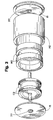
- Fig. 1 is an exploded view of a moving magnet embodiment.
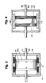
- Fig. 2 is a sectional view of the embodiment shown in Fig. 1.
- Fig. 3 is an exploded view of a moving coil embodiment.
- Fig. 4 is a sectional view of the embodiment shown in Fig. 3.
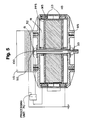
- Fig. 5 shows an embodiment of the invention particularly suitable for vibration control.
- FIG. 1 and 2 there is shown an embodiment of the present invention which is of the moving magnet type.
- a permanent magnet structure or armature M1 is mounted on an actuator shaft S1 and magnetized in an axial direction.
- the shaft S1 is slidably mounted at its ends within a magnetically permeable housing H1 which is open at both ends along the axis of the shaft S1.
- the armature M1 is a magnet stack which contains one or more coaxially positioned permanent magnets and two or more pole plates PP1.
- a plate PP1 is placed between each magnet and at either end of the magnet stack. In case of more than one magnet, the magnets are stacked on the shaft S1 in such a way that equal magnetic poles face each other.
- the armature M1 in this embodiment is cylindrical with a circular cross-section but could be of any arbitrary shape.
- Two or more solenoidal coils C1 are wound on a non magnetic bobbin B1 mounted within the housing H1.
- the coils C1 are spaced from each other in an axial direction so as to form rings on the bobbin B1.
- the inside diameter fits around the magnet structure M1 with some minimal diametrical clearance so as to allow free axial motion of the armature structure M1.
- the outside diameter of the bobbin B1 fits snugly inside the cylindrical steel housing H1.
- the coils C1 are electrically connected with each other in such a way that an electrical current flowing through adjacent coils C1 will create opposing magnetic fields.
- the open ends of the cylindrical outer housing H1 are closed off with non magnetic endcaps 15 at each end with a sleeve bearing 20 in the center of each endcap 15.
- the housing H1 is made of magnetically soft steel while the endcaps 15 are made of aluminum or other non-magnetic material.
- the bearings 20 guide the actuator shaft S1 and center the armature M1. When an electrical input current is applied to the coils C1, the armature M1 is subjected to reciprocal forces in accordance with the input current signal.
- the magnetically permeable housing H1, nonmagnetic endcaps 15, and nonmagnetic bobbin B1 cause the field produced by the magnet stack to be concentrated and directed more perpendicularly toward the coils C1.
- FIG. 3 and 4 there is shown another embodiment of the present invention which is of the moving coil type.
- Two or more annular magnet segments M2 are attached on the inside of an outer housing H2 made of highly magnetically permeable material such as magnetically soft steel.
- the housing H2 is closed at each end with non-magnetic endcaps 15.
- the magnets M2 are magnetized in a radial direction.
- Adjacent magnets M2 have their N-S poles oriented in opposite directions.
- Two or more field coils C2 are wound on a thin walled magnetic steel cylinder 25.
- a non-magnetic core 26 occupies the center of the cylinder 25.
- the coils C2 are spaced from each other with a non-magnetic material 27.
- An actuator shaft S2 is mounted in the center of the core 27 and shaft S2 is slidably mounted within the housing H2 by means of sleeve bearings 20 in each endcap 15.
- the coils C2 are electrically connected so that an input current applied to the coils creates opposing magnet fields in each adjacent coil C2 which also causes the field coils C2 to undergo reciprocal motion in accordance with the input signal.
- the housing H1 cylinder 25, and nonmagnetic endcaps 15 provide a magnetic flux path for the magnets M2 which concentrates and directs perpendicularly their fields toward the coils C2.
- the magnets by enclosing the magnets with a material having high magnetic permeability (i.e., housing H1 or H2), most of the magnetic flux is guided through the magnetic gap in which the coils C1 or C2 are placed. Only very little flux will leak past this gap, thus creating a highly efficient electromagnetic actuator.
- the first embodiment all the flux in the pole plates PP1 is guided through the coils.
- the cylinder 25 provides a low reluctance pathway for the flux produced by the magnets M2.
- the nonmagnetic endcaps 15 help to direct the permanent magnet flux perpendicularly toward the coils C1 or C2.
- Each of the embodiments of the present invention also provides an actuator which presents a low inductance load to the electrical input signal. Since the change in input current due to a change in the input voltage signal occurs with a time constant proportional to this inductance, reducing this inductance results in a more linear relationship between the input signal and the force applied to the moving element.
- the inductance is reduced by electrically connecting adjacent coils in series so as to create opposing magnetic fields. An inductive coupling between adjacent coils occurs due to a linkage of magnetic fields created when a current runs through the coils. When the direction of the current in two adjacent coils is the same, the resulting magnetic fields are added and the total inductance of the combination is double the inductance of a single coil.
- the embodiments described above also provide an actuator where the force on the moving element (i.e., either the coil or the magnet) due to a given input current is independent of the position of the moving element along its stroke path.
- This is achieved in the first embodiment by providing coils C1 adjacent to each pole of the magnets making up the armature M1.
- an annular magnet M2 is provided adjacent each of the coils C2.
- the actuator shown is of the moving magnet type as described earlier with reference to Figs. 1 and 2. Accordingly, the actuator comprises a housing H3 having mounted there within field coils C3 electrically connected so as to create opposing magnetic fields when an electrical input signal is applied to the coils.
- the magnetic armature M3 is magnetized in the axial direction so that the magnetic fields produced by the current-carrying coils C3 produce a force on the armature M3.
- the housing H3 and pole plates PP3 provide a low reluctance pathway for the magnetic flux.
- the shaft S3 is mounted stationarily within the housing H3 while the armature M3 is slidably mounted on the shaft.
- the armature M3 thus undergoes reciprocal motion in accordance with the input current applied to the coils C3 and is unimpeded by any mechanical load other than minimal frictional resistance.
- the housing H3 is shown as being stationarily mounted between a vibration source VS and a mounting surface MS.
- the actuator is physically connected to the vibration source by means of amount 50 made of rubber or similar material attached to a metal plate 51. If an input signal produced by a suitable feedback control system which senses the vibrations of the vibrating surface is applied to the coils C3, the armature M3 undergoes reciprocal motion in accordance with the input signal.
- FIG. 5 shows a processing unit PU into which is fed a signal from vibration sensor 100 and which then generates the driving signal to coils C3 in a manner so as to reduce the sensed vibrations.
- the armature has mass, this motion of the armature causes reaction forces to be imparted to the housing H3 due to conservation of momentum. These reaction forces then act so as to prevent the transmission of vibrations between the vibration source VS and the mounting surface MS. Because the armature moves freely, these reaction forces are the same for a given input current regardless of the strength of the vibrational forces produced by the source VS.
- the actuator of Fig. 5 can be used to actively control the vibrations produced by an automobile engine and prevent those vibrations from being transmitted to the automobile frame.
- the mounting surface MS is the automobile frame while the vibration source VS is the engine.
- the mount 50 is then a rubber engine mount which secures the engine to the frame.
- the actuator described above with reference to Fig. 5 could also be of the moving coil type.
- the armature could be stationarily mounted on a slidably mounted shaft as long as there is room at each end of the housing for the shaft to extend when at the limits of its stroke.
- the armature M3 of the actuator described above if perturbed from its equilibrium middle position, will oscillate with a certain natural frequency due to the restoring force of the internal magnetic field which causes the armature to seek a position with a flux path of minimum reluctance. This natural frequency is dependent upon the strength of the restoring force and the mass of the armature. Since the frequency response of the actuator depends upon this natural frequency, it may be desireable in certain applications to alter the natural frequency by the addition of internal springs R1 within the housing H3.
- the actuator of Fig. 5 is simply mounted on the vibrating surface VS alone.
- the reaction forces produced by the actuator then act so as to reduce the vibrations of the surface VS.
Landscapes
- Engineering & Computer Science (AREA)
- Power Engineering (AREA)
- General Engineering & Computer Science (AREA)
- Physics & Mathematics (AREA)
- Electromagnetism (AREA)
- Mechanical Engineering (AREA)
- Reciprocating, Oscillating Or Vibrating Motors (AREA)
- Arrangement Or Mounting Of Propulsion Units For Vehicles (AREA)
- Buildings Adapted To Withstand Abnormal External Influences (AREA)
- Apparatuses For Generation Of Mechanical Vibrations (AREA)
- Vibration Prevention Devices (AREA)
- Electromagnets (AREA)
- Agricultural Chemicals And Associated Chemicals (AREA)
Claims (13)
- Elektromagnetischer Aktuator für Anwendungen zur aktiven Vibrationssteuerung, mit:- einem Gehäuse (H), das dazu ausgelegt ist, an einer vibrierenden Oberfläche (VS) montiert zu werden;- einem beweglichen Element (S), das gleitbar innerhalb des Gehäuses (H) gelagert ist;- Mitteln (M, C), um das bewegliche Element (S) in Antwort auf ein elektrisches Eingangssignal in eine lineare Hin-und Herbewegung in einer Richtung zu zwingen, die senkrecht zu den zwei Oberflächen ist; und- Mitteln (100) zum Erfassen der Vibrationen der vibrierenden Oberfläche (VS) und zum Erzeugen des elektrischen Eingangssignals, das den Mitteln (M, C) zum Erzwingen der Bewegung zugeführt wird;wobei die Bewegung des beweglichen Elementes (S) Reaktionskräfte auf das Gehäuse (H) aufgrund der Masse des beweglichen Elementes (S) und der Speicherung von Trägheitsmoment erzeugt, die dazu verwendet werden können, die Vibrationen der vibrierenden Oberfläche (VS) zu verringern;
gekennzeichnet durchdie Tatsache, daß das Gehäuse (H) dazu ausgelegt ist, zwischen der vibrierenden Oberfläche (VS) und einer nicht vibrierenden Montageoberfläche (MS) montiert zu werden; undnichtmagnetische Abschlußkappen (15), die an jedem Ende des Gehäuses (H) montiert sind. - Aktuator nach Anspruch 1, der weiterhin Mittel aufweist zum Montieren des Aktuators zwischen einer vibrierenden Oberfläche (VS) und einer nicht vibrierenden Oberfläche (MS).
- Aktuator nach Anspruch 1 oder Anspruch 2, der weiterhin Federn (R1) aufweist, die innerhalb des Gehäuses (H) angeordnet sind und auf das bewegliche Element (S) wirken, um die Eigenvibrationsfrequenz des beweglichen Elementes zu verändern und hierdurch die Frequenzantwort des Aktuators zu ändern.
- Aktuator nach Anspruch 1, der weiterhin Federn (R1) aufweist, die das bewegliche Element (S) abstützen.
- Aktuator nach einem der vorhergehenden Ansprüche, wobei:das bewegliche Element eine Permanentmagnetstruktur (M1) aufweist, die an einer Welle (S1) montiert ist, wobei die Welle (S1) an jedem Ende innerhalb des Gehäuses (H) montiert ist, wobei das Gehäuse (H) aus einem Material mit hoher magnetischer Permeabilität hergestellt und an beiden Enden entlang der Achse der Welle (S1) offen ist, und wobei die Permanentmagnetstruktur in einer axialen Richtung magnetisiert ist;die Mittel zum Erzwingen der linearen Hin- und Herbewegung des beweglichen Elementes eine Vielzahl von Spulen (C1) aufweisen, die um einen nichtmagnetischen Spulenkörper (B1) gewickelt sind, der koaxial innerhalb des Gehäuses montiert ist, wobei die Permanentmagnetstruktur (M1) innerhalb des Spulenkörpers (B1) angeordnet ist, wobei sich die Pole des Magneten jeweils in enger Nähe zu einer Spule (C1) befinden, die so angeordnet sind, daß eine Axialkraft auf die Permanentmagnetstruktur (M1) in Übereinstimmung mit der Polarität und der Amplitude des Eingangssignals angelegt wird, wenn die Spulen durch das elektrische Eingangssignal erregt werden;die nichtmagnetischen Abschlußkappen (15) an jedem Ende des Gehäuses Enden der Welle (S1) lagern, wobei die Abschlußkappen die Ausrichtung des Magnetfeldes der Permanentmagnetstruktur (M1) senkrechter auf die Spulen zu halten;die Spulen (C1) elektrisch miteinander derart verbunden sind, daß benachbarte Spulen entgegengesetzte Magnetfelder erzeugen, wenn sie erregt werden, um dem elektrischen Eingangssignal eine Last mit geringer Induktivität zu zeigen und um Flußmodulationen in der Magnetstruktur zu eliminieren;die Spulen (C1) jeweils benachbart zu den Polen der Permanentmagnetstruktur (M1) angeordnet sind, wobei die Abmessungen der Spulen und die der Permanentmagnetstruktur derart sind, daß der von der Permanentmagnetstruktur auf die Spulen auftreffende Magnetfluß relativ gesehen konstant bleibt, wenn sich die Magnetstruktur in einer Axialrichtung bewegt; undwobei die Permanentmagnetstruktur ein Magnetstapel ist, der einen oder mehrere koaxial angeordnete Permanentmagnete aufweist, wobei an jedem Ende des Magnetstapels und zwischen den Magneten jeweils Polplatten (PP1) vorgesehen sind.
- Aktuator nach Anspruch 5, wobei die Permanentmagnetstruktur (M3) gleitbar an der Welle (S3) gelagert ist und wobei die Welle (S3) stationär innerhalb des Gehäuses (H3) montiert ist.
- Aktuator nach Anspruch 5, wobei die Welle (S1) gleitbar innerhalb des Gehäuses (H1) montiert ist und wobei die Permanentmagnetstruktur (M1) stationär an der Welle (S1) montiert ist.
- Aktuator nach einem der Ansprüche 1 - 4, wobei:das bewegliche Element einen Zylinder (25) aufweist, der koaxial an einer Welle (S2) montiert ist, die an jedem Ende innerhalb des Gehäuses (H2) montiert ist, wobei das Gehäuse (H2) aus einem Material mit hoher magnetischer Permeabilität hergestellt und an beiden Enden entlang der Achse der Welle (S2) offen ist;eine Vielzahl von Spulen (C2) um den Zylinder (25) herumgewickelt sind;entsprechend zu jeder Spule (C2) ein ringförmiger Permanentmagnet (M2) koaxial an dem Innenumfang des Gehäuses (H2) montiert und in einer radialen Richtung magnetisiert ist, wobei jeder Permanentmagnet (M2) in enger Nähe zu einer Spule (C2) positioniert und derart ausgelegt ist, daß eine Axialkraft auf die Spulen in Übereinstimmung mit der Polarität und der Amplitude des Eingangssignals angelegt wird, wenn die Spulen (C2) durch das elektrische Eingangssignal erregt werden;die nichtmagnetischen Abschlußkappen (15) an jedem Ende des Gehäuses (H2) Enden der Welle (S2) lagern, wobei die Abschlußkappen die Ausrichtung des Magnetfeldes der ringförmigen Permanentmagneten senkrechter in Richtung auf die Spulen (C2) halten;die Spulen (C2) elektrisch miteinander verbunden sind, so daß benachbarte Spulen entgegengesetzte Magnetfelder erzeugen, wenn sie erregt werden, um dem elektrischen Eingangssignal eine Last geringer Induktivität zu zeigen und Flußmodulationen in der Magnetstruktur zu eliminieren; undwobei ein ringförmiger Magnet (M2) benachbart zu jeder der Spulen (C2) angeordnet ist, wobei die Abmessungen der Spulen und der ringförmigen Magnete derart gewählt sind, daß der von den ringförmigen Magneten auf die Spulen auftreffenden Magnetfluß relativ gesehen konstant bleibt, wenn sich die Spulen in einer axialen Richtung bewegen.
- Aktuator nach Anspruch 8, wobei der Zylinder (25) gleitbar an der Welle gelagert ist und wobei die Welle stationär in dem Gehäuse (H2) montiert ist.
- Aktuator nach Anspruch 8, wobei die Welle (S2) gleitbar in dem Gehäuse (H2) gelagert ist und wobei der Zylinder (25) stationär an der Welle (S2) montiert ist.
- Aktuator nach einem der Ansprüche 8 - 10, der weiterhin einen nichtmagnetischen Kern (26) aufweist, der den mittleren Bereich des Zylinders (25) einnimmt, und wobei die Feldspulen an dem Zylinder (25) durch ein nichtmagnetisches Material voneinander getrennt sind.
- Aktuator nach einem der vorhergehenden Ansprüche, der weiterhin Mittel aufweist, um den Aktuator mit dem Eingangssignal anzusteuern, um unerwünschten Vibrationen entgegenzuwirken.
- System zum aktiven Auslöschen von Primärvibrationen, die von einer Vibrationsquelle (VS) ausgehen, durch Erzeugen von Sekundärvibrationen, mit:Mitteln zum Erfassen von Restvibrationen, die nach der Interaktion der Primär- und der Sekundärvibrationen verbleiben;Mitteln zum Erzeugen eines elektrischen Signales in Übereinstimmung mit einem Signal, das von den Vibrationserfassungsmitteln empfangen ist, um einen Aktuator derart anzusteuern, daß die erfaßten Vibrationen reduziert werden; undeinem elektromagnetischen Aktuator gemäß einem der vorhergehenden Ansprüche zum Erzeugen von Sekundärvibrationen.
Applications Claiming Priority (3)
| Application Number | Priority Date | Filing Date | Title |
|---|---|---|---|
| US816658 | 1992-01-03 | ||
| US07/816,658 US5231336A (en) | 1992-01-03 | 1992-01-03 | Actuator for active vibration control |
| PCT/US1992/011359 WO1993013586A1 (en) | 1992-01-03 | 1992-12-31 | Actuator for active vibration control |
Publications (3)
| Publication Number | Publication Date |
|---|---|
| EP0574574A1 EP0574574A1 (de) | 1993-12-22 |
| EP0574574A4 EP0574574A4 (de) | 1995-03-29 |
| EP0574574B1 true EP0574574B1 (de) | 1997-06-18 |
Family
ID=25221284
Family Applications (1)
| Application Number | Title | Priority Date | Filing Date |
|---|---|---|---|
| EP93902871A Expired - Lifetime EP0574574B1 (de) | 1992-01-03 | 1992-12-31 | Betätiger für aktive vibrationssteuerung |
Country Status (10)
| Country | Link |
|---|---|
| US (1) | US5231336A (de) |
| EP (1) | EP0574574B1 (de) |
| JP (1) | JPH06505676A (de) |
| AT (1) | ATE154731T1 (de) |
| AU (1) | AU661111B2 (de) |
| CA (1) | CA2105308A1 (de) |
| DE (1) | DE69220482T2 (de) |
| NO (1) | NO933130L (de) |
| NZ (1) | NZ246767A (de) |
| WO (1) | WO1993013586A1 (de) |
Cited By (6)
| Publication number | Priority date | Publication date | Assignee | Title |
|---|---|---|---|---|
| EP4191846A1 (de) * | 2011-04-26 | 2023-06-07 | Kokusai Keisokuki Kabushiki Kaisha | Elektrodynamischer aktuator und elektrodynamische anregungsvorrichtung |
| WO2023144045A1 (en) * | 2022-01-25 | 2023-08-03 | Robert Bosch Gmbh | Methods, materials & structures for manufacturing a magnetically actuated exciter device using 3d printing |
| US11781941B2 (en) | 2022-01-25 | 2023-10-10 | Robert Bosch Gmbh | Multi-degree-of-freedom impedance fixture for automated frequency response function measurements |
| US12104987B2 (en) | 2022-01-25 | 2024-10-01 | Robert Bosch Gmbh | Analyzing quality of sensed force-response data during testing and mitigation poor quality output |
| US12105060B2 (en) | 2022-01-25 | 2024-10-01 | Robert Bosch Gmbh | Magnetically actuated exciter device with impact function |
| US12255512B2 (en) | 2022-01-25 | 2025-03-18 | Robert Bosch Gmbh | Axial and radial suspension for a magnetically actuated exciter device |
Families Citing this family (111)
| Publication number | Priority date | Publication date | Assignee | Title |
|---|---|---|---|---|
| US5319938A (en) * | 1992-05-11 | 1994-06-14 | Macrosonix Corp. | Acoustic resonator having mode-alignment-canceled harmonics |
| US5682069A (en) * | 1994-08-30 | 1997-10-28 | Harris Corporation | Concentrically mounted vibration attenuator and method |
| US5535853A (en) * | 1994-11-14 | 1996-07-16 | Otis Elevator Company | Actuator having a two ended actuator rod movable longitudinally and transversely |
| ES2286821T3 (es) * | 1995-04-18 | 2007-12-01 | Harman International Industries Incorporated | Activador de doble bobina con alojamiento multifuncion. |
| US5901809A (en) * | 1995-05-08 | 1999-05-11 | Berkun; Andrew | Apparatus for supplying compressed air |
| US5638303A (en) * | 1995-06-28 | 1997-06-10 | Mcdonnell Douglas Corporation | Non-contacting isolated stabilized microgravity platform system |
| US5740082A (en) * | 1995-12-21 | 1998-04-14 | Mcdonnell Douglas Corporation | Collocated sensor actuator |
| JP3493592B2 (ja) * | 1996-02-20 | 2004-02-03 | Necトーキン株式会社 | ペイジャー用振動アクチュエータ |
| US5701113A (en) * | 1996-02-28 | 1997-12-23 | Mcdonnell Douglas Corporation | Passive non-contacting centering system |
| CN1077966C (zh) * | 1996-04-08 | 2002-01-16 | 株式会社三角工具加工 | 具有阻尼特性的磁弹簧和具有所述磁弹簧的振动机构 |
| US5913091A (en) * | 1996-05-21 | 1999-06-15 | Minolta Co., Ltd. | Image reading apparatus |
| US5844815A (en) * | 1996-10-08 | 1998-12-01 | Mcdonnell Douglas Corporation | Umbilical and follower assembly utilized in microgravity platform system |
| JP3725272B2 (ja) * | 1996-12-27 | 2005-12-07 | 株式会社デルタツーリング | 振動発生機構 |
| US6009985A (en) * | 1997-02-10 | 2000-01-04 | Lord Corporation | Efficient multi-directional active vibration absorber assembly |
| US5884736A (en) * | 1997-03-31 | 1999-03-23 | Virginia Tech Intellectual Properties, Inc. | Active dual reaction mass absorber for vibration control |
| US5957440A (en) * | 1997-04-08 | 1999-09-28 | Lord Corporation | Active fluid mounting |
| US5947457A (en) * | 1997-04-08 | 1999-09-07 | Lord Corporation | Fluid-filled active vibration absorber |
| US6213737B1 (en) * | 1997-04-18 | 2001-04-10 | Ebara Corporation | Damper device and turbomolecular pump with damper device |
| JPH1130274A (ja) * | 1997-05-15 | 1999-02-02 | Delta Tsuuring:Kk | 磁気バネを有する振動機構 |
| KR100281474B1 (ko) | 1997-05-16 | 2001-02-01 | 후지타 히토시 | 자기스프링을구비한에너지출력기구 |
| US5961899A (en) * | 1997-07-15 | 1999-10-05 | Lord Corporation | Vibration control apparatus and method for calender rolls and the like |
| US6768806B1 (en) | 1998-03-19 | 2004-07-27 | Harman International Industries, Incorporated | Shorting rings in dual-coil dual-gap loudspeaker drivers |
| JPH11351322A (ja) * | 1998-06-05 | 1999-12-24 | Tokai Rubber Ind Ltd | 能動的防振用加振器 |
| DE19832244C2 (de) * | 1998-07-17 | 2000-10-19 | Rollei Fototechnic Gmbh | Elektromagnetischer Antrieb für einen Schlitzverschluß |
| US5973422A (en) * | 1998-07-24 | 1999-10-26 | The Guitammer Company | Low frequency vibrator |
| US6296093B1 (en) * | 1998-11-09 | 2001-10-02 | Lord Corportion | Vibration-damped machine and control method therefor |
| US6242823B1 (en) | 1999-02-05 | 2001-06-05 | Wayne Griswold | Linear electric machine |
| US6470751B1 (en) * | 1999-02-20 | 2002-10-29 | Lg Electronics Inc. | Vibration detecting apparatus and method thereof |
| US6869375B2 (en) * | 2001-02-27 | 2005-03-22 | Sikorsky Aircraft Corporation | High output force actuator for an active vibration control system |
| US6861771B2 (en) * | 2003-03-26 | 2005-03-01 | Asm Technology Singapore Pte. Ltd. | Active vibration attenuation |
| US7958801B2 (en) * | 2003-10-01 | 2011-06-14 | Sikorsky Aircraft Corporation | Harmonic force generator for an active vibration control system |
| FR2860658B1 (fr) * | 2003-10-01 | 2006-01-13 | Hutchinson | Dispositif actif d'amortissement de vibrations d'un element vibrant |
| US6938889B2 (en) * | 2003-10-15 | 2005-09-06 | Pao-An Chuang | Shock absorbing and magnetic levitating cushion |
| US7288861B1 (en) * | 2004-03-06 | 2007-10-30 | Motran Industries Inc. | Inertial actuator with multiple flexure stacks |
| CN100535473C (zh) * | 2004-06-10 | 2009-09-02 | 洛德公司 | 控制直升机振动的方法和系统 |
| US20060030872A1 (en) * | 2004-08-03 | 2006-02-09 | Brad Culbert | Dilation introducer for orthopedic surgery |
| US7378765B2 (en) * | 2004-08-09 | 2008-05-27 | Oriental Motor Co., Ltd. | Cylinder-type linear motor and moving part thereof |
| US8162606B2 (en) | 2004-08-30 | 2012-04-24 | Lord Corporation | Helicopter hub mounted vibration control and circular force generation systems for canceling vibrations |
| US7722322B2 (en) * | 2004-08-30 | 2010-05-25 | Lord Corporation | Computer system and program product for controlling vibrations |
| US8267652B2 (en) * | 2004-08-30 | 2012-09-18 | Lord Corporation | Helicopter hub mounted vibration control and circular force generation systems for canceling vibrations |
| CN101022994B (zh) | 2004-08-30 | 2012-07-04 | 洛德公司 | 直升飞机振动控制系统和消除振动的旋转力发生器 |
| JP2006075734A (ja) * | 2004-09-09 | 2006-03-23 | Namiki Precision Jewel Co Ltd | 偏平振動アクチュエータ |
| US20060056993A1 (en) * | 2004-09-14 | 2006-03-16 | Moshe Gombinsky | Magnetic spring actuator device |
| WO2006063014A2 (en) * | 2004-12-06 | 2006-06-15 | Renaissance Sound, Llc | Acoustic wave generating apparatus and method |
| JP2006177547A (ja) * | 2004-12-21 | 2006-07-06 | Hyundai Motor Co Ltd | 車両用振動制御装置の動吸振器構造 |
| US20060236456A1 (en) * | 2005-03-03 | 2006-10-26 | Beale Robert S | Patient transport method and apparatus |
| US7449803B2 (en) * | 2005-03-21 | 2008-11-11 | Sahyoun Joseph Y | Electromagnetic motor to create a desired low frequency vibration or to cancel an undesired low frequency vibration |
| US7768160B1 (en) | 2005-03-21 | 2010-08-03 | Sahyoun Joseph Y | Electromagnetic motor to create a desired low frequency vibration or to cancel an undesired low frequency vibration |
| DE602005008019D1 (de) * | 2005-05-16 | 2008-08-21 | Agusta Spa | Hubschrauber mit verbesserter Schwingungskontrollvorrichtung |
| JP4802307B2 (ja) * | 2005-06-29 | 2011-10-26 | 並木精密宝石株式会社 | 振動アクチュエータ |
| WO2007020599A2 (en) * | 2005-08-16 | 2007-02-22 | Koninklijke Philips Electronics, N.V. | Resonant actuator for a personal care appliance having a programmable actuation capability |
| WO2007029325A1 (ja) * | 2005-09-08 | 2007-03-15 | Namiki Seimitsu Houseki Kabusikikaisha | 扁平振動アクチュエー タ |
| US20070210653A1 (en) * | 2006-03-13 | 2007-09-13 | Scanlon Matthew J | Moving magnet actuator with counter-cogging end-ring and asymmetrical armature stroke |
| US7550880B1 (en) | 2006-04-12 | 2009-06-23 | Motran Industries Inc | Folded spring flexure suspension for linearly actuated devices |
| US20080036303A1 (en) * | 2006-06-15 | 2008-02-14 | Clive Graham Stevens | Linear motor for imparting vibration to a supported body |
| US20080001484A1 (en) * | 2006-07-03 | 2008-01-03 | Chris Fuller | Linear Electromechanical Vibrator with Axially Movable Magnet |
| US7859144B1 (en) | 2006-08-31 | 2010-12-28 | Joseph Y Sahyoun | Low frequency electromagnetic motor to create or cancel a low frequency vibration |
| CA2665700C (en) * | 2006-10-12 | 2013-11-19 | Bell Helicopter Textron Inc. | Vibration-attenuating hard-mounted pylon |
| EP2034594B1 (de) * | 2007-08-16 | 2021-09-29 | ViZaar AG | Elektromagnetischer Linearmotor |
| WO2009055007A2 (en) * | 2007-10-25 | 2009-04-30 | Lord Corporation | Distributed active vibration control systems and rotary wing aircraft with suppressed vibrations |
| US20130281776A1 (en) * | 2008-08-11 | 2013-10-24 | Tricatalyst, Llc | Sexual Stimulation Devices and Methods |
| US9107797B2 (en) | 2008-08-11 | 2015-08-18 | Tricatalyst, Llc | Sexual stimulation devices and methods |
| DE102008061205A1 (de) * | 2008-11-18 | 2010-05-20 | Institut für Luft- und Kältetechnik gemeinnützige Gesellschaft mbH | Elektrodynamischer Linearschwingmotor |
| US8860337B2 (en) | 2009-05-18 | 2014-10-14 | Resonant Systems, Inc. | Linear vibration modules and linear-resonant vibration modules |
| US8097987B2 (en) * | 2009-07-31 | 2012-01-17 | Hiwin Mikrosystem Corp. | Movable magnet type linear motor with improved end cover assembly |
| US8129870B1 (en) | 2009-08-04 | 2012-03-06 | Pusl Kenneth E | Asymmetric folded spring flexure suspension system for reciprocating devices |
| US9325232B1 (en) | 2010-07-22 | 2016-04-26 | Linear Labs, Inc. | Method and apparatus for power generation |
| FR2964579B1 (fr) | 2010-09-15 | 2012-09-28 | Peugeot Citroen Automobiles Sa | Batteur actif comportant une piece d'equilibrage et vehicule automobile equipe d'un tel batteur |
| FR2965600B1 (fr) * | 2010-10-05 | 2013-09-27 | Peugeot Citroen Automobiles Sa | Batteur actif a guidage optimise |
| CA2814530C (en) * | 2010-10-22 | 2019-09-10 | Linear Labs, Inc. | An improved magnetic motor |
| US8475748B2 (en) | 2011-02-25 | 2013-07-02 | Cognis Ip Management Gmbh | Metal solvent extraction reagents and use thereof |
| KR101223069B1 (ko) | 2011-05-30 | 2013-01-17 | (주) 디에이치홀딩스 | 능동타입 에코페달장치 |
| US9590463B2 (en) * | 2011-09-22 | 2017-03-07 | Minebea Co., Ltd. | Vibration generator moving vibrator by magnetic field generated by coil and holder used in vibration-generator |
| JP5930388B2 (ja) * | 2012-04-20 | 2016-06-08 | 日本電産セイミツ株式会社 | 振動発生装置 |
| WO2013169303A1 (en) | 2012-05-09 | 2013-11-14 | Yknots Industries Llc | Adaptive haptic feedback for electronic devices |
| US10108265B2 (en) | 2012-05-09 | 2018-10-23 | Apple Inc. | Calibration of haptic feedback systems for input devices |
| WO2013188307A2 (en) | 2012-06-12 | 2013-12-19 | Yknots Industries Llc | Haptic electromagnetic actuator |
| US9886116B2 (en) | 2012-07-26 | 2018-02-06 | Apple Inc. | Gesture and touch input detection through force sensing |
| WO2014036567A1 (en) | 2012-09-03 | 2014-03-06 | Linear Labs, Inc. | An improved transducer and method of operation |
| US9219962B2 (en) | 2012-09-03 | 2015-12-22 | Linear Labs, Inc. | Transducer and method of operation |
| US20140117786A1 (en) * | 2012-10-25 | 2014-05-01 | Kendall C. Gosvener | Magnetically Actuated Reciprocating Motor and Process Using Reverse Magnetic Switching |
| US10099780B2 (en) * | 2013-10-07 | 2018-10-16 | Sikorsky Aircraft Corporation | Active vibration control actuator |
| USD747641S1 (en) * | 2014-01-10 | 2016-01-19 | Nordost Corporation | Vibration damper |
| US20150242037A1 (en) | 2014-01-13 | 2015-08-27 | Apple Inc. | Transparent force sensor with strain relief |
| US10297119B1 (en) * | 2014-09-02 | 2019-05-21 | Apple Inc. | Feedback device in an electronic device |
| US9939901B2 (en) | 2014-09-30 | 2018-04-10 | Apple Inc. | Haptic feedback assembly |
| JP6289396B2 (ja) * | 2014-10-28 | 2018-03-07 | アズビル株式会社 | アクチュエータ |
| EP3043087A1 (de) * | 2015-01-07 | 2016-07-13 | BAE Systems PLC | Verbesserungen an und im Zusammenhang mit elektromechanischen Aktuatoren |
| US10458502B2 (en) | 2015-01-07 | 2019-10-29 | Bae Systems Plc | Relating to electromechanical actuators |
| EP3262310B1 (de) | 2015-02-26 | 2020-10-28 | Carrier Corporation | Magnetlager |
| US10927892B2 (en) | 2015-02-26 | 2021-02-23 | Carrier Corporation | Magnetic thrust bearing |
| US9798409B1 (en) | 2015-03-04 | 2017-10-24 | Apple Inc. | Multi-force input device |
| US9837939B1 (en) | 2015-04-01 | 2017-12-05 | Lockheed Martin Corporation | System and method for providing vibration isolation by magnetic levitation |
| GB2548803B (en) * | 2016-03-22 | 2021-09-15 | Animal Dynamics Ltd | Linear actuator |
| US11296587B2 (en) * | 2016-11-30 | 2022-04-05 | Massachusetts Institute Of Technology | High force and low noise linear fine-tooth motor |
| JP2018143041A (ja) * | 2017-02-28 | 2018-09-13 | 日本電産セイミツ株式会社 | 振動モータ |
| WO2018182891A1 (en) | 2017-04-01 | 2018-10-04 | Carrier Corporation | Magnetic radial bearing with flux boost |
| WO2018182872A1 (en) | 2017-04-01 | 2018-10-04 | Carrier Corporation | Magnetic radial bearing with flux boost |
| CN110462235B (zh) | 2017-04-01 | 2021-08-03 | 开利公司 | 具有磁通升高的磁径向轴承 |
| US10848044B1 (en) | 2017-08-14 | 2020-11-24 | The Government Of The United States Of America, As Represented By The Secretary Of The Navy | Linear electromagnetic actuator |
| US10908306B2 (en) * | 2018-05-10 | 2021-02-02 | Geospectrum Technologies Inc. | Underwater acoustic source and actuator |
| KR102457741B1 (ko) * | 2018-12-28 | 2022-10-24 | 한국알박(주) | 진공 분위기에서 사용되는 전자석 어셈블리 및 그 제조 방법 |
| EP3954133B1 (de) | 2019-04-11 | 2024-02-21 | Continental Engineering Services GmbH | Schwingungsaktuator für steife strukturen zur hochleistungs-basswiedergabe im automobilbereich |
| US11035179B2 (en) | 2019-11-05 | 2021-06-15 | Saudi Arabian Oil Company | Disconnecting a stuck drill pipe |
| DE102020213768A1 (de) * | 2020-11-02 | 2022-05-05 | Continental Engineering Services Gmbh | Aktuator zur Anregung von Schwingungen umfassend einen Antrieb mit verbesserter Dämpfung |
| US11682513B1 (en) * | 2021-01-06 | 2023-06-20 | The United States Of America, As Represented By The Secretary Of The Navy | Linearized pull-pull electromagnetic actuators, systems, and methods |
| CN217388499U (zh) * | 2021-05-06 | 2022-09-06 | 瑞声光电科技(常州)有限公司 | 线性振动电机 |
| US11817755B2 (en) * | 2021-06-01 | 2023-11-14 | Apple Inc. | Axisymmetric linear resonant actuators |
| EP4551809A1 (de) * | 2022-07-08 | 2025-05-14 | Vestas Wind Systems A/S | Dämpfungsanordnung für eine windturbine |
| US12573931B1 (en) * | 2024-06-16 | 2026-03-10 | David Deak, SR. | Vibration powered energy harvesting generator with metallic glass layer having high permeability, around coil structure |
| CN120169656B (zh) * | 2025-05-19 | 2025-08-22 | 浙江大学 | 一种圆柱型电磁换能器 |
Family Cites Families (35)
| Publication number | Priority date | Publication date | Assignee | Title |
|---|---|---|---|---|
| US1912167A (en) * | 1931-07-13 | 1933-05-30 | Leroy J Leahy | Electrical reciprocating motor |
| US3135880A (en) * | 1958-11-10 | 1964-06-02 | Tronics Corp | Linear motion electromagnetic machines |
| US3148292A (en) * | 1959-11-06 | 1964-09-08 | Linear eddy-current electromagnetic actuator | |
| US3119940A (en) * | 1961-05-16 | 1964-01-28 | Sperry Rand Corp | Magnetomotive actuators of the rectilinear output type |
| US3202886A (en) * | 1962-01-11 | 1965-08-24 | Bulova Watch Co Inc | Bistable solenoid |
| GB981439A (en) * | 1962-03-27 | 1965-01-27 | Trench Electric Ltd | Electromagnetic axially reciprocating motors or generators and armatures therefor |
| US3590293A (en) * | 1969-09-29 | 1971-06-29 | Gen Electric | Dynamoelectric machine having a stationary assembly of the permanent magnet type |
| US3790834A (en) * | 1970-11-21 | 1974-02-05 | T Tanaka | Low speed synchronous motor |
| US3952979A (en) * | 1975-02-19 | 1976-04-27 | Hughes Aircraft Company | Isolator |
| US4363980A (en) * | 1979-06-05 | 1982-12-14 | Polaroid Corporation | Linear motor |
| US4612592A (en) * | 1979-12-26 | 1986-09-16 | Burroughs Corporation | Dual coil/dual magnet actuator |
| US4692999A (en) * | 1979-12-26 | 1987-09-15 | Unisys Corp. | Method of making a multi-coil/multi-magnet actuator |
| US4868432A (en) * | 1979-12-26 | 1989-09-19 | Unisys Corporation (Formerly Burroughs Corp) | Multi-coil actuator with end cap flux carrier |
| JPS56141769A (en) * | 1980-04-07 | 1981-11-05 | Ryoda Sato | Low voltage linear motor |
| JPS5859368U (ja) * | 1981-10-15 | 1983-04-21 | 住友特殊金属株式会社 | 直流モ−タ用磁気回路 |
| GB2110422A (en) * | 1981-11-27 | 1983-06-15 | Philips Electronic Associated | Electromechanical bistable arrangements |
| JPS5964A (ja) * | 1982-06-24 | 1984-01-05 | 杉山 賢一 | 撰択加熱可能の家庭用浴槽装置 |
| JPS5959064A (ja) * | 1982-09-29 | 1984-04-04 | Takahashi Yoshiteru | 可動マグネツト型ブラシレスリニアモ−タ |
| US4508988A (en) * | 1982-12-21 | 1985-04-02 | Kollmorgen Technologies Corporation | Permanent magnet motor stator for d.c. motors |
| JPS61164459A (ja) * | 1985-01-11 | 1986-07-25 | Showa Electric Wire & Cable Co Ltd | リニアモ−タ |
| DE3538017A1 (de) * | 1985-10-25 | 1987-04-30 | Triumph Adler Ag | Elektrischer antrieb |
| DE3674370D1 (de) * | 1985-11-28 | 1990-10-25 | Ebara Corp | Elektrisch angetriebenes geraet. |
| JPS63217965A (ja) * | 1987-03-05 | 1988-09-12 | Shinko Electric Co Ltd | リニアモ−タ |
| JPS6439255A (en) * | 1987-08-03 | 1989-02-09 | Tokin Corp | Magnetic circuit for linear motor |
| JP2535181B2 (ja) * | 1987-09-30 | 1996-09-18 | 株式会社シコー技研 | 電機子巻線が重畳しない5相の直流電動機 |
| JPH0197249A (ja) * | 1987-10-08 | 1989-04-14 | Asahi Chem Ind Co Ltd | カーリング防止機能を有する経編地 |
| JPH01164256A (ja) * | 1987-12-18 | 1989-06-28 | Aisin Seiki Co Ltd | リニア発電機 |
| GB2214724A (en) * | 1988-01-28 | 1989-09-06 | Custom Dev Ltd | Permanent magnet electric motor |
| US4885489A (en) * | 1988-03-30 | 1989-12-05 | Honeywell Inc. | Permanent magnet motor with hysteresis drag cup coupling |
| US4922159A (en) * | 1988-05-09 | 1990-05-01 | Harris Corporation | Linear precision actuator with accelerometer feedback |
| DE3824257A1 (de) * | 1988-07-14 | 1990-01-18 | Johannes Keller | Linearer magnetantrieb fuer turbinenlader mit pufferung |
| US5113104A (en) * | 1989-10-19 | 1992-05-12 | General Electric Company | Structured product dynamoelectric machine |
| US5138209A (en) * | 1990-03-01 | 1992-08-11 | Nippon Densan Corporation | Spindle motor |
| US5095238A (en) * | 1990-04-03 | 1992-03-10 | Minebea Co., Ltd. | Brushless dc motor and rotor magnet |
| JPH08102501A (ja) * | 1994-09-30 | 1996-04-16 | Nippon Steel Corp | 半導体装置 |
-
1992
- 1992-01-03 US US07/816,658 patent/US5231336A/en not_active Expired - Lifetime
- 1992-12-31 DE DE69220482T patent/DE69220482T2/de not_active Expired - Lifetime
- 1992-12-31 AU AU34288/93A patent/AU661111B2/en not_active Ceased
- 1992-12-31 WO PCT/US1992/011359 patent/WO1993013586A1/en not_active Ceased
- 1992-12-31 EP EP93902871A patent/EP0574574B1/de not_active Expired - Lifetime
- 1992-12-31 NZ NZ246767A patent/NZ246767A/en unknown
- 1992-12-31 AT AT93902871T patent/ATE154731T1/de not_active IP Right Cessation
- 1992-12-31 JP JP5511969A patent/JPH06505676A/ja active Pending
- 1992-12-31 CA CA002105308A patent/CA2105308A1/en not_active Abandoned
-
1993
- 1993-09-02 NO NO933130A patent/NO933130L/no unknown
Cited By (8)
| Publication number | Priority date | Publication date | Assignee | Title |
|---|---|---|---|---|
| EP4191846A1 (de) * | 2011-04-26 | 2023-06-07 | Kokusai Keisokuki Kabushiki Kaisha | Elektrodynamischer aktuator und elektrodynamische anregungsvorrichtung |
| US11824416B2 (en) | 2011-04-26 | 2023-11-21 | Kokusai Keisokuki Kabushiki Kaisha | Electrodynamic actuator and electrodynamic excitation device |
| WO2023144045A1 (en) * | 2022-01-25 | 2023-08-03 | Robert Bosch Gmbh | Methods, materials & structures for manufacturing a magnetically actuated exciter device using 3d printing |
| US11781941B2 (en) | 2022-01-25 | 2023-10-10 | Robert Bosch Gmbh | Multi-degree-of-freedom impedance fixture for automated frequency response function measurements |
| US12104987B2 (en) | 2022-01-25 | 2024-10-01 | Robert Bosch Gmbh | Analyzing quality of sensed force-response data during testing and mitigation poor quality output |
| US12105060B2 (en) | 2022-01-25 | 2024-10-01 | Robert Bosch Gmbh | Magnetically actuated exciter device with impact function |
| US12205761B2 (en) | 2022-01-25 | 2025-01-21 | Robert Bosch Gmbh | Methods, materials and structures for manufacturing a magnetically actuated exciter device using 3D printing |
| US12255512B2 (en) | 2022-01-25 | 2025-03-18 | Robert Bosch Gmbh | Axial and radial suspension for a magnetically actuated exciter device |
Also Published As
| Publication number | Publication date |
|---|---|
| EP0574574A4 (de) | 1995-03-29 |
| WO1993013586A1 (en) | 1993-07-08 |
| DE69220482D1 (de) | 1997-07-24 |
| EP0574574A1 (de) | 1993-12-22 |
| ATE154731T1 (de) | 1997-07-15 |
| CA2105308A1 (en) | 1993-07-04 |
| AU3428893A (en) | 1993-07-28 |
| NZ246767A (en) | 1995-12-21 |
| AU661111B2 (en) | 1995-07-13 |
| JPH06505676A (ja) | 1994-06-30 |
| DE69220482T2 (de) | 1998-02-05 |
| NO933130L (no) | 1993-11-01 |
| US5231336A (en) | 1993-07-27 |
| NO933130D0 (no) | 1993-09-02 |
Similar Documents
| Publication | Publication Date | Title |
|---|---|---|
| US5231336A (en) | Actuator for active vibration control | |
| US7768160B1 (en) | Electromagnetic motor to create a desired low frequency vibration or to cancel an undesired low frequency vibration | |
| US6565072B2 (en) | Damping actuator and active vibration damping device equipped with the actuator | |
| US7449803B2 (en) | Electromagnetic motor to create a desired low frequency vibration or to cancel an undesired low frequency vibration | |
| EP1101273B1 (de) | Tieffrequenzschwinger | |
| US6105943A (en) | Active damping oscillator having non-connected shaft member and outer sleeve movable relative to each other by energization of coils | |
| US4542311A (en) | Long linear stroke reciprocating electric machine | |
| CA2493603C (en) | Actuator capable of moving in axial and rotational directions | |
| US5444313A (en) | Electromagnetic actuator having two opposite phase movable parts | |
| JP2002525007A5 (de) | ||
| EP1835602B1 (de) | Beweglicher magnetischer Aktor mit gegenverzahntem Abschlussring und asymmetrischem Ankerhub | |
| JP2002525007A (ja) | 振動するバネ質量体システムを備えた電磁アクチエータ | |
| EP1023764B1 (de) | Elektromagnetische vorrichtung zur erzeugung einer linearen bewegung | |
| EP4207809A1 (de) | Schalldiffusor und verfahren zur diffusion eines schalls durch einen schalldiffusor | |
| CA2085920C (en) | Rubber mount | |
| CA2280973C (en) | Apparatus for producing linear motion | |
| US8049375B2 (en) | Electromagnetic transducer apparatus | |
| GB2367110A (en) | A vibration isolation mount | |
| JP3404139B2 (ja) | 電磁アクチュエータ | |
| JP3733745B2 (ja) | 能動型制振器 | |
| JPH0612796A (ja) | 磁気ヘッド・アクチュエータ | |
| JPH0993900A (ja) | 振動アクチュエータ | |
| JP2601240Y2 (ja) | 振動アクチュエータ | |
| JPH11341782A (ja) | コイル可動形リニア直流モータ | |
| JPH09107670A (ja) | リニア直流モータ |
Legal Events
| Date | Code | Title | Description |
|---|---|---|---|
| PUAI | Public reference made under article 153(3) epc to a published international application that has entered the european phase |
Free format text: ORIGINAL CODE: 0009012 |
|
| AK | Designated contracting states |
Kind code of ref document: A1 Designated state(s): AT BE CH DE DK ES FR GB GR IE IT LI LU NL PT SE |
|
| 17P | Request for examination filed |
Effective date: 19931215 |
|
| A4 | Supplementary search report drawn up and despatched | ||
| AK | Designated contracting states |
Kind code of ref document: A4 Designated state(s): AT BE CH DE DK ES FR GB GR IE IT LI LU NL PT SE |
|
| 17Q | First examination report despatched |
Effective date: 19950816 |
|
| GRAG | Despatch of communication of intention to grant |
Free format text: ORIGINAL CODE: EPIDOS AGRA |
|
| GRAH | Despatch of communication of intention to grant a patent |
Free format text: ORIGINAL CODE: EPIDOS IGRA |
|
| GRAH | Despatch of communication of intention to grant a patent |
Free format text: ORIGINAL CODE: EPIDOS IGRA |
|
| GRAA | (expected) grant |
Free format text: ORIGINAL CODE: 0009210 |
|
| RAP1 | Party data changed (applicant data changed or rights of an application transferred) |
Owner name: HARMAN INTERNATIONAL INDUSTRIES INCORPORATED |
|
| AK | Designated contracting states |
Kind code of ref document: B1 Designated state(s): AT BE CH DE DK ES FR GB GR IE IT LI LU NL PT SE |
|
| PG25 | Lapsed in a contracting state [announced via postgrant information from national office to epo] |
Ref country code: NL Free format text: LAPSE BECAUSE OF FAILURE TO SUBMIT A TRANSLATION OF THE DESCRIPTION OR TO PAY THE FEE WITHIN THE PRESCRIBED TIME-LIMIT Effective date: 19970618 Ref country code: LI Effective date: 19970618 Ref country code: IT Free format text: LAPSE BECAUSE OF FAILURE TO SUBMIT A TRANSLATION OF THE DESCRIPTION OR TO PAY THE FEE WITHIN THE PRE;WARNING: LAPSES OF ITALIAN PATENTS WITH EFFECTIVE DATE BEFORE 2007 MAY HAVE OCCURRED AT ANY TIME BEFORE 2007. THE CORRECT EFFECTIVE DATE MAY BE DIFFERENT FROM THE ONE RECORDED.SCRIBED TIME-LIMIT Effective date: 19970618 Ref country code: GR Free format text: LAPSE BECAUSE OF FAILURE TO SUBMIT A TRANSLATION OF THE DESCRIPTION OR TO PAY THE FEE WITHIN THE PRESCRIBED TIME-LIMIT Effective date: 19970618 Ref country code: FR Effective date: 19970618 Ref country code: ES Free format text: THE PATENT HAS BEEN ANNULLED BY A DECISION OF A NATIONAL AUTHORITY Effective date: 19970618 Ref country code: DK Effective date: 19970618 Ref country code: CH Effective date: 19970618 Ref country code: BE Effective date: 19970618 Ref country code: AT Effective date: 19970618 |
|
| REF | Corresponds to: |
Ref document number: 154731 Country of ref document: AT Date of ref document: 19970715 Kind code of ref document: T |
|
| REG | Reference to a national code |
Ref country code: CH Ref legal event code: EP |
|
| REF | Corresponds to: |
Ref document number: 69220482 Country of ref document: DE Date of ref document: 19970724 |
|
| PG25 | Lapsed in a contracting state [announced via postgrant information from national office to epo] |
Ref country code: SE Effective date: 19970918 Ref country code: PT Effective date: 19970918 |
|
| EN | Fr: translation not filed | ||
| NLV1 | Nl: lapsed or annulled due to failure to fulfill the requirements of art. 29p and 29m of the patents act | ||
| PG25 | Lapsed in a contracting state [announced via postgrant information from national office to epo] |
Ref country code: LU Free format text: LAPSE BECAUSE OF NON-PAYMENT OF DUE FEES Effective date: 19971231 Ref country code: IE Free format text: LAPSE BECAUSE OF NON-PAYMENT OF DUE FEES Effective date: 19971231 |
|
| REG | Reference to a national code |
Ref country code: CH Ref legal event code: PL |
|
| PLBE | No opposition filed within time limit |
Free format text: ORIGINAL CODE: 0009261 |
|
| STAA | Information on the status of an ep patent application or granted ep patent |
Free format text: STATUS: NO OPPOSITION FILED WITHIN TIME LIMIT |
|
| 26N | No opposition filed | ||
| REG | Reference to a national code |
Ref country code: GB Ref legal event code: IF02 |
|
| PGFP | Annual fee paid to national office [announced via postgrant information from national office to epo] |
Ref country code: GB Payment date: 20101229 Year of fee payment: 19 |
|
| PGFP | Annual fee paid to national office [announced via postgrant information from national office to epo] |
Ref country code: DE Payment date: 20111229 Year of fee payment: 20 |
|
| REG | Reference to a national code |
Ref country code: DE Ref legal event code: R071 Ref document number: 69220482 Country of ref document: DE |
|
| REG | Reference to a national code |
Ref country code: GB Ref legal event code: PE20 Expiry date: 20121230 |
|
| PG25 | Lapsed in a contracting state [announced via postgrant information from national office to epo] |
Ref country code: GB Free format text: LAPSE BECAUSE OF EXPIRATION OF PROTECTION Effective date: 20121230 |
|
| PG25 | Lapsed in a contracting state [announced via postgrant information from national office to epo] |
Ref country code: DE Free format text: LAPSE BECAUSE OF EXPIRATION OF PROTECTION Effective date: 20130101 |