EP0574601A1 - Verbessertes Verfahren und Gerät für optische Zwischenwirkungs- und Durchlassungsvermögenmessungen - Google Patents
Verbessertes Verfahren und Gerät für optische Zwischenwirkungs- und Durchlassungsvermögenmessungen Download PDFInfo
- Publication number
- EP0574601A1 EP0574601A1 EP92110082A EP92110082A EP0574601A1 EP 0574601 A1 EP0574601 A1 EP 0574601A1 EP 92110082 A EP92110082 A EP 92110082A EP 92110082 A EP92110082 A EP 92110082A EP 0574601 A1 EP0574601 A1 EP 0574601A1
- Authority
- EP
- European Patent Office
- Prior art keywords
- specimen
- illumination
- probe
- optical information
- optical
- Prior art date
- Legal status (The legal status is an assumption and is not a legal conclusion. Google has not performed a legal analysis and makes no representation as to the accuracy of the status listed.)
- Granted
Links
- 230000003287 optical effect Effects 0.000 title claims abstract description 64
- 238000005259 measurement Methods 0.000 title claims abstract description 45
- 238000000034 method Methods 0.000 title claims abstract description 45
- 238000002834 transmittance Methods 0.000 title claims abstract description 22
- 239000000523 sample Substances 0.000 claims abstract description 46
- 238000005286 illumination Methods 0.000 claims description 51
- 238000001514 detection method Methods 0.000 claims description 29
- 239000000835 fiber Substances 0.000 claims description 29
- 238000012545 processing Methods 0.000 claims description 9
- 230000008569 process Effects 0.000 claims description 2
- 230000004044 response Effects 0.000 claims description 2
- 230000005540 biological transmission Effects 0.000 abstract description 9
- 230000003993 interaction Effects 0.000 abstract description 3
- 238000013461 design Methods 0.000 abstract description 2
- 238000000926 separation method Methods 0.000 abstract description 2
- 230000003595 spectral effect Effects 0.000 abstract description 2
- 230000002708 enhancing effect Effects 0.000 abstract 1
- 238000001228 spectrum Methods 0.000 description 7
- 238000010521 absorption reaction Methods 0.000 description 4
- 239000011248 coating agent Substances 0.000 description 4
- 238000000576 coating method Methods 0.000 description 4
- 239000010410 layer Substances 0.000 description 4
- 239000012491 analyte Substances 0.000 description 3
- 239000000463 material Substances 0.000 description 3
- 238000013459 approach Methods 0.000 description 2
- 230000000694 effects Effects 0.000 description 2
- 239000000203 mixture Substances 0.000 description 2
- 239000002344 surface layer Substances 0.000 description 2
- 238000012935 Averaging Methods 0.000 description 1
- 240000008042 Zea mays Species 0.000 description 1
- 235000005824 Zea mays ssp. parviglumis Nutrition 0.000 description 1
- 235000002017 Zea mays subsp mays Nutrition 0.000 description 1
- 238000002835 absorbance Methods 0.000 description 1
- 235000005822 corn Nutrition 0.000 description 1
- 238000009792 diffusion process Methods 0.000 description 1
- 239000003085 diluting agent Substances 0.000 description 1
- 230000003292 diminished effect Effects 0.000 description 1
- 230000009977 dual effect Effects 0.000 description 1
- 235000013399 edible fruits Nutrition 0.000 description 1
- 230000001747 exhibiting effect Effects 0.000 description 1
- 238000003384 imaging method Methods 0.000 description 1
- 230000031700 light absorption Effects 0.000 description 1
- 239000007788 liquid Substances 0.000 description 1
- 230000007246 mechanism Effects 0.000 description 1
- 238000012986 modification Methods 0.000 description 1
- 230000004048 modification Effects 0.000 description 1
- 210000003205 muscle Anatomy 0.000 description 1
- 235000016709 nutrition Nutrition 0.000 description 1
- 230000035764 nutrition Effects 0.000 description 1
- 239000013307 optical fiber Substances 0.000 description 1
- 230000035515 penetration Effects 0.000 description 1
- 239000000843 powder Substances 0.000 description 1
- 230000005855 radiation Effects 0.000 description 1
- 125000006850 spacer group Chemical group 0.000 description 1
- 238000000411 transmission spectrum Methods 0.000 description 1
- 235000013311 vegetables Nutrition 0.000 description 1
Images


Classifications
-
- G—PHYSICS
- G01—MEASURING; TESTING
- G01N—INVESTIGATING OR ANALYSING MATERIALS BY DETERMINING THEIR CHEMICAL OR PHYSICAL PROPERTIES
- G01N21/00—Investigating or analysing materials by the use of optical means, i.e. using sub-millimetre waves, infrared, visible or ultraviolet light
- G01N21/17—Systems in which incident light is modified in accordance with the properties of the material investigated
- G01N21/47—Scattering, i.e. diffuse reflection
- G01N21/4738—Diffuse reflection, e.g. also for testing fluids, fibrous materials
- G01N21/474—Details of optical heads therefor, e.g. using optical fibres
-
- G—PHYSICS
- G01—MEASURING; TESTING
- G01N—INVESTIGATING OR ANALYSING MATERIALS BY DETERMINING THEIR CHEMICAL OR PHYSICAL PROPERTIES
- G01N21/00—Investigating or analysing materials by the use of optical means, i.e. using sub-millimetre waves, infrared, visible or ultraviolet light
- G01N21/17—Systems in which incident light is modified in accordance with the properties of the material investigated
Definitions
- the present invention relates to an improved method and apparatus for performing optical interactance and transmittance measurements and, in particular, such method and apparatus where undesired information is discriminated against and desired information is enhanced. Reflectance measurements on small amounts of specimen are also encompassed by the invention.
- a further cause of interference is nonhomogeneous or layered distribution of specimen characteristics, e.g., the layers of skin and fat which cover muscle tissue, the skin which covers the flesh of a fruit or vegetable, or the coating of windows through which measurements are to be made. Often, it is desirable to eliminate the affects of the surface layers to provide information on the underlying portions of the specimen.
- the present invention is directed to solving these problems which cause inaccuracies in spectroscopic determination of qualitative or quantitative characteristics of the specimen.
- Dual pathlength transmission cells with separate detection have been proposed to remove the effects of window coating in transmission measurements through clear liquids. This approach is equivalent to placing a second cell of different thickness in the reference beam of a dual-beam spectrometer. Effects common to the two paths, such as absorption due to the window material, equal deposits on the windows, atmospheric absorption, and the specimen absorption in the equal portion of the pathlength are canceled by taking the simple ratio of the signals derived from the two paths.
- Diffuse transmittance and reflectance measurements are usually made on large volumes of specimen to reduce errors by averaging the inhomogeneities.
- the usual procedure is to grind each specimen into a fine powder and mix it with a nonabsorbing diluent or to spread it on a diffusely reflecting background so as to present a large area for reflectance measurement.
- a method for improving optical interactance measurements comprises the steps of providing illumination by way of a plurality of paths through a specimen having a characteristic to be measured, sensing two or more independent signals developed at the same time or in rapid sequence representing optical information from said specimen and processing said signals in accordance with appropriate modeling techniques to minimize inaccuracies in spectroscopic determination of qualitative of quantitative characteristics of the specimen.
- apparatus for improving optical interactance measurements comprises means for providing illumination through a specimen having a characteristic to be measured along a plurality of different paths, means for sensing optical information provided from an illuminated specimen, means for developing a plurality of independent signals corresponding in number to said plurality of paths, the signals representing the optical information obtained from the specimen and means for processing the signals in accordance with appropriate modeling techniques to minimize inaccuracies in spectroscopic determination of quantitative or qualitative characteristics of the specimen.
- a first aspect of this invention comprises the use of three or more optical apertures shared among the source and illumination functions so as to provide two or more independent signals for further processing and analysis.
- Figure 1A a probe utilizing fiber optics is shown which has two ring apertures surrounding a central round aperture.
- the probe 10 includes a cylindrical outer body 30 in which a concentric inner body 31 is arranged.
- the inner body 31 tapers at the examining end to a central aperture 15.
- the outer body 30 constriots at the examining end to define a conical, inwardly directed wall.
- the tapered end of the inner body 31 defines a second conical wall. Between these two walls is disposed a conical dividing element 33.
- the angles defined by the two walls and the conical dividing element are preferably the same.
- Conical annular spaces or rings (shown in cross-section as 14, 13, 12 and 11) are defined by the two walls and dividing element. In these annular spaces or rings are disposed, in conical fashion, optical fibers 16 and 17 for supplying illumination to the specimen.
- one or more lenses 20 for focusing and transmitting incident light entering the aperture 15.
- each ring is used for illumination by fiber optic elements while the central detection aperture is connected by fiber optics to a detection system, such as a diode-array spectrophotometer.
- the central aperture in one embodiment is 1.2 mm diameter, and the inner ring has a mean diameter of 6 mm with a width of 1 mm. The mean spacing from the inner ring to the central aperture is therefore 3 mm and the minimum spacing is 1.9 mm.
- the outer ring has a mean diameter of 12 mm and a width of 1 mm, providing a mean spacing from source to detection of 6 mm and a minimum spacing of 4.9 mm.
- the tip portion of the probe and the fiber optic elements at the tip portion are angled at approximately 26° with respect to the longitudinal axis of the probe.
- the central detection assembly is movable axially.
- the detection aperture at the distal end of this assembly is normally positioned in the same plane as the source ring apertures, however, it may be moved back and lenses inserted so as to image a detection area on the specimen into the aperture of the detection fibers.
- the lenses 20 in the inner body of the probe are interchangeable and the positions of the lenses and the central detection assembly are adjustable by means of spacers.
- lenses and arrangements for three different specimen sizes for reflectance and one arrangement for interactance are listed in the following Table 1:
- This reimaging allows control of the size of the detection area and the angular cone within which energy is detected by changing the lenses and their spacing.
- the energy source fibers are arranged in conical form.
- introduction of the energy at an angle directed toward the detector improves the efficiency.
- This feature also provides for diffuse reflectance and transmittance measurements using the same probe as discussed below.
- each source fiber optic bundle preferably, has a small percentage of its input fibers brought out 50 so that the associated source intensity and modulation can be monitored. It will be obvious to one skilled in the art that additional source rings may be provided, each with its distinctive modulation, and that the operation may be reversed to provide a single source by using two or more detection rings coupled to multiple or time- shared detection means.
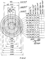
- Figure 2 shows a design comprising 10 large area (8 to 28 mm2 active area) ring apertures, nominally designated as source rings, and a central aperture plus 2 additional rings of smaller area (2.9 to 3.4 mm2) nominally considered as detection rings.
- the source ring active area is adjusted by the density of active fibers within each ring.
- This structure allows selection of a wide variety of spacings and locations for the measurements using combinations of the three different detection apertures and 10 source apertures. While the examples shown here show ring geometries, other geometries, such as parallel slits or small apertures, which provide substantially constant values of the spacing between all points within a given source aperture and those within a given detection aperture may be used.
- the signals may then be expressed as K1*T1*I1 and K2*T1*I2 where K1 and K2 are system functions involving the relative source intensities, the gain through the system, scattering losses and similar factors.
- the ratio is therefore (K1/K2) * (I1/I2) and the window coating transmission has been eliminated from the result. Note that any factors common to K1 and K2 are also canceled as in the normal use of a reference and the remainder factors may be adjusted so that the K factor becomes unity. Taking the log of the ratio yields "absorbance" A equal to log(I1) - log(I2) .
- log(I) will equal (a*t) and the log difference becomes a*(t1-t2) where a is the "absorptivity" spectrum which is linearly related to concentration.
- a is the "absorptivity" spectrum which is linearly related to concentration.
- the various signals are derived by absorption of light through different combinations of materials within the specimen. All the signals contain information on the surface layers while the signals derived from the larger spacings contain information on the deeper layers that is diminished or lacking in the signals measured with smaller spacings.
- these signals may be combined in a linear or nonlinear chemometric model so as to extract the desired information. In this case, it is helpful to have the input energy for each source aperture as an additional measured quantity for use in the modeling.
- Each class of specimens requires a different form of model, and subclasses require determination of various model parameters during the calibration process.
- the specimen may be held in a small hole drilled in a flat plate mounted approximately 2 to 4 mm from the end of the fiber-optic probe. It is illuminated via one or both of the outer ring bundles at an angle of incidence of approximately 45 degrees.
- the plate to finished with a mirror surface so that incident energy outside the area of the specimen is reflected at approximately 45 degrees from the normal.
- the diffusely reflected energy is collected by imaging the specimen surface on the central fiber bundle via lenses whose optical axes are coincident with the axis of the probe assembly. The power and spacing of the lenses may be selected so as to select the desired sample area.
- a diffuse or specular reflector may be placed behind the specimen to increase its apparent depth by a factor of at least two.
- the axis of the probe may be positioned vertically with the apertures at the top and a transparent window, such as a microscope slide, positioned with its upper surface at the appropriate distance from the apertures. Specimens may be placed on the window for measurement. Three measurements may be made:
- the "no specimen” energy spectrum it subtracted from the spectrum of the specimen and the spectrum of the reference to correct for residual energy reflected or scattered from the window.
- Still another aspect of the invention is the measurement of diffuse transmission through small specimens.
- the specimen is mounted in a hole on a plate and illuminated as previously described for reflectance measurements.
- the receiving fiber-optic bundle is placed behind the sample so as to collect the transmitted energy.
- the conical illumination pattern is helpful in achieving rapid diffusion of energy within the specimen thereby improving the repeatability of measurements on small specimens.
- simultaneous or time shared measurement of both the diffusely transmitted and diffusely reflected energy is possible. The combination of these two measurements allows additional information to be obtained concerning the absorption and scattering characteristics of the specimen.
- Still another embodiment utilizes the probe as described above for reflection and an additional fiber bundle is employed behind the specimen to illuminate it. Therefore, the same receiver is utilized for transmittance and reflectance with two different illumination sources being provided. A switching arrangement may be used to alternate between the illumination sources.
- the central detection element may comprise the detector itself rather than the fiberoptic detector bundle.
- an alternate embodiment can be constructed where the direction of light flow can use the light source being provided at the control aperture and one or more of the fiber optic bundles responsive to specimen information.
Landscapes
- Physics & Mathematics (AREA)
- Health & Medical Sciences (AREA)
- Life Sciences & Earth Sciences (AREA)
- Chemical & Material Sciences (AREA)
- Analytical Chemistry (AREA)
- Biochemistry (AREA)
- General Health & Medical Sciences (AREA)
- General Physics & Mathematics (AREA)
- Immunology (AREA)
- Pathology (AREA)
- Investigating Or Analysing Materials By Optical Means (AREA)
Priority Applications (2)
| Application Number | Priority Date | Filing Date | Title |
|---|---|---|---|
| EP19920110082 EP0574601B1 (de) | 1992-06-15 | 1992-06-15 | Verbessertes Verfahren und Gerät für optische Zwischenwirkungs- und Durchlassungsvermögenmessungen |
| DE1992627025 DE69227025T2 (de) | 1992-06-15 | 1992-06-15 | Verbessertes Verfahren und Gerät für optische Zwischenwirkungs- und Durchlassungsvermögenmessungen |
Applications Claiming Priority (1)
| Application Number | Priority Date | Filing Date | Title |
|---|---|---|---|
| EP19920110082 EP0574601B1 (de) | 1992-06-15 | 1992-06-15 | Verbessertes Verfahren und Gerät für optische Zwischenwirkungs- und Durchlassungsvermögenmessungen |
Publications (2)
| Publication Number | Publication Date |
|---|---|
| EP0574601A1 true EP0574601A1 (de) | 1993-12-22 |
| EP0574601B1 EP0574601B1 (de) | 1998-09-16 |
Family
ID=8209710
Family Applications (1)
| Application Number | Title | Priority Date | Filing Date |
|---|---|---|---|
| EP19920110082 Expired - Lifetime EP0574601B1 (de) | 1992-06-15 | 1992-06-15 | Verbessertes Verfahren und Gerät für optische Zwischenwirkungs- und Durchlassungsvermögenmessungen |
Country Status (2)
| Country | Link |
|---|---|
| EP (1) | EP0574601B1 (de) |
| DE (1) | DE69227025T2 (de) |
Cited By (3)
| Publication number | Priority date | Publication date | Assignee | Title |
|---|---|---|---|---|
| NL1011905C2 (nl) * | 1999-04-27 | 2000-10-30 | Co Peratie Rundveeverbetering | Inrichting voor het analyseren van melk en daarvoor bestemde sensor. |
| WO2000064242A1 (en) * | 1999-04-27 | 2000-11-02 | Coöperatie Rundveeverbetering Delta U.A. | Measuring head for a device for analysing products |
| WO2003060458A1 (en) * | 2002-01-17 | 2003-07-24 | Agilent Technologies, Inc. | Determination of optical properties of a device under test in both directions in transmission and in reflection |
Families Citing this family (1)
| Publication number | Priority date | Publication date | Assignee | Title |
|---|---|---|---|---|
| US7061616B2 (en) | 2002-03-28 | 2006-06-13 | Samsung Electronics Co., Ltd. | Optical transceiver and method for image density measurement |
Citations (5)
| Publication number | Priority date | Publication date | Assignee | Title |
|---|---|---|---|---|
| US3786266A (en) * | 1969-05-19 | 1974-01-15 | Atomic Energy Authority Uk | Methods and apparatus for distinguishing between bodies according to their translucency |
| US4627014A (en) * | 1984-04-09 | 1986-12-02 | Eastman Kodak Company | Method and apparatus for determination of an analyte and method of calibrating such apparatus |
| US4633087A (en) * | 1985-04-24 | 1986-12-30 | Trebor Industries, Inc. | Near infrared apparatus for measurement of organic constituents of material |
| US4800885A (en) * | 1987-12-02 | 1989-01-31 | The Boc Group, Inc. | Blood constituent monitoring apparatus and methods with frequency division multiplexing |
| EP0351994A2 (de) * | 1988-07-19 | 1990-01-24 | Beckman Instruments, Inc. | Bestimmung der Konzentration mit Blitzlichtphotometern mit mehrfachen Wellenlängen |
-
1992
- 1992-06-15 EP EP19920110082 patent/EP0574601B1/de not_active Expired - Lifetime
- 1992-06-15 DE DE1992627025 patent/DE69227025T2/de not_active Expired - Fee Related
Patent Citations (5)
| Publication number | Priority date | Publication date | Assignee | Title |
|---|---|---|---|---|
| US3786266A (en) * | 1969-05-19 | 1974-01-15 | Atomic Energy Authority Uk | Methods and apparatus for distinguishing between bodies according to their translucency |
| US4627014A (en) * | 1984-04-09 | 1986-12-02 | Eastman Kodak Company | Method and apparatus for determination of an analyte and method of calibrating such apparatus |
| US4633087A (en) * | 1985-04-24 | 1986-12-30 | Trebor Industries, Inc. | Near infrared apparatus for measurement of organic constituents of material |
| US4800885A (en) * | 1987-12-02 | 1989-01-31 | The Boc Group, Inc. | Blood constituent monitoring apparatus and methods with frequency division multiplexing |
| EP0351994A2 (de) * | 1988-07-19 | 1990-01-24 | Beckman Instruments, Inc. | Bestimmung der Konzentration mit Blitzlichtphotometern mit mehrfachen Wellenlängen |
Non-Patent Citations (2)
| Title |
|---|
| THE AMERICAN JOURNAL OF CLINICAL NUTRITION vol. 40, 1 December 1984, pages 1123 - 1130 J.CONWAY ET AL. 'A NEW APPROACH FOR THE ESTIMATION OF BODY COMPOSITION,ETC.' * |
| TRANSACTIONS OF THE ASAE vol. 21, no. 3, 1 June 1978, pages 581 - 584 E.FINNEY ET AL. 'DETERMINATION OF MOISTURE IN CORN KERNELS,ETC.' WHOLE DOCUMENT * |
Cited By (3)
| Publication number | Priority date | Publication date | Assignee | Title |
|---|---|---|---|---|
| NL1011905C2 (nl) * | 1999-04-27 | 2000-10-30 | Co Peratie Rundveeverbetering | Inrichting voor het analyseren van melk en daarvoor bestemde sensor. |
| WO2000064242A1 (en) * | 1999-04-27 | 2000-11-02 | Coöperatie Rundveeverbetering Delta U.A. | Measuring head for a device for analysing products |
| WO2003060458A1 (en) * | 2002-01-17 | 2003-07-24 | Agilent Technologies, Inc. | Determination of optical properties of a device under test in both directions in transmission and in reflection |
Also Published As
| Publication number | Publication date |
|---|---|
| DE69227025T2 (de) | 1999-06-02 |
| DE69227025D1 (de) | 1998-10-22 |
| EP0574601B1 (de) | 1998-09-16 |
Similar Documents
| Publication | Publication Date | Title |
|---|---|---|
| US5935062A (en) | Diffuse reflectance monitoring apparatus | |
| US4734584A (en) | Quantitative near-infrared measurement instrument for multiple measurements in both reflectance and transmission modes | |
| US5258825A (en) | Optical compositional analyzer apparatus and method for detection of ash in wheat and milled wheat products | |
| US7142307B1 (en) | Method and apparatus for optical interactance and transmittance measurements | |
| EP1576345B1 (de) | Optisches analysesystem | |
| US5028139A (en) | Readhead for reflectance measurement of distant samples | |
| EP0965824B1 (de) | Gerät und Verfahren zur spektroskopischen Transmissions- und Reflexionsanalyse | |
| US6268910B1 (en) | Method and apparatus for screening plasma for interferents in plasma from donor blood bags | |
| EP0206433A2 (de) | Verfahren zur Messung des Lichtabsorptionsvermögens eines Flüssigkeitsmediums | |
| US6111653A (en) | Translucency measurement | |
| EP0815434A4 (de) | Diffus reflektierende sonde | |
| JPH06186159A (ja) | 近赤外透過スペクトルによる果実糖度の非破壊測定法 | |
| US20040027659A1 (en) | Sample holder | |
| KR100460972B1 (ko) | 핸드-헬드적외선분광계를사용한폐기카펫확인방법및장치 | |
| US4657398A (en) | Simultaneous multiple wavelength photometer | |
| US20020186363A1 (en) | Method and apparatus for screening plasma for interferents in plasma from donor blood bags | |
| EP0032774A2 (de) | Optische Reflektionsmesseinrichtung | |
| EP0574601B1 (de) | Verbessertes Verfahren und Gerät für optische Zwischenwirkungs- und Durchlassungsvermögenmessungen | |
| US7623906B2 (en) | Diffuse reflectance spectroscopy | |
| WO2005100955A1 (en) | Method and apparatus for determining the absorption of weakly absorbing and/or scattering liquid samples | |
| WO1988009920A1 (en) | Near infrared measurement apparatus for organic materials | |
| DE19751403A1 (de) | Kombinierte Absorptions- und Reflektanzspektroskopie zur synchronen Ermittlung der Absorption, Fluoreszenz, Streuung und Brechung von Flüssigkeiten, Gasen und Festkörpern | |
| RU103924U1 (ru) | Датчик со смещенными каналами | |
| Birth | Applications of electro-optical techniques to nondestructive quality evaluation of foods |
Legal Events
| Date | Code | Title | Description |
|---|---|---|---|
| PUAI | Public reference made under article 153(3) epc to a published international application that has entered the european phase |
Free format text: ORIGINAL CODE: 0009012 |
|
| AK | Designated contracting states |
Kind code of ref document: A1 Designated state(s): DE FR GB |
|
| 17P | Request for examination filed |
Effective date: 19940513 |
|
| 17Q | First examination report despatched |
Effective date: 19960612 |
|
| GRAG | Despatch of communication of intention to grant |
Free format text: ORIGINAL CODE: EPIDOS AGRA |
|
| GRAG | Despatch of communication of intention to grant |
Free format text: ORIGINAL CODE: EPIDOS AGRA |
|
| GRAG | Despatch of communication of intention to grant |
Free format text: ORIGINAL CODE: EPIDOS AGRA |
|
| GRAH | Despatch of communication of intention to grant a patent |
Free format text: ORIGINAL CODE: EPIDOS IGRA |
|
| GRAH | Despatch of communication of intention to grant a patent |
Free format text: ORIGINAL CODE: EPIDOS IGRA |
|
| GRAA | (expected) grant |
Free format text: ORIGINAL CODE: 0009210 |
|
| AK | Designated contracting states |
Kind code of ref document: B1 Designated state(s): DE FR GB |
|
| REF | Corresponds to: |
Ref document number: 69227025 Country of ref document: DE Date of ref document: 19981022 |
|
| ET | Fr: translation filed | ||
| PLBE | No opposition filed within time limit |
Free format text: ORIGINAL CODE: 0009261 |
|
| STAA | Information on the status of an ep patent application or granted ep patent |
Free format text: STATUS: NO OPPOSITION FILED WITHIN TIME LIMIT |
|
| 26N | No opposition filed | ||
| REG | Reference to a national code |
Ref country code: GB Ref legal event code: IF02 |
|
| PGFP | Annual fee paid to national office [announced via postgrant information from national office to epo] |
Ref country code: GB Payment date: 20080630 Year of fee payment: 17 |
|
| PGFP | Annual fee paid to national office [announced via postgrant information from national office to epo] |
Ref country code: FR Payment date: 20081201 Year of fee payment: 17 |
|
| PGFP | Annual fee paid to national office [announced via postgrant information from national office to epo] |
Ref country code: DE Payment date: 20081223 Year of fee payment: 17 |
|
| GBPC | Gb: european patent ceased through non-payment of renewal fee |
Effective date: 20090615 |
|
| REG | Reference to a national code |
Ref country code: FR Ref legal event code: ST Effective date: 20100226 |
|
| PG25 | Lapsed in a contracting state [announced via postgrant information from national office to epo] |
Ref country code: FR Free format text: LAPSE BECAUSE OF NON-PAYMENT OF DUE FEES Effective date: 20090630 |
|
| PG25 | Lapsed in a contracting state [announced via postgrant information from national office to epo] |
Ref country code: GB Free format text: LAPSE BECAUSE OF NON-PAYMENT OF DUE FEES Effective date: 20090615 |
|
| PG25 | Lapsed in a contracting state [announced via postgrant information from national office to epo] |
Ref country code: DE Free format text: LAPSE BECAUSE OF NON-PAYMENT OF DUE FEES Effective date: 20100101 |