EP0574610A1 - Conteneur pour le transport de liquides à transferer dans des bouteilles - Google Patents
Conteneur pour le transport de liquides à transferer dans des bouteilles Download PDFInfo
- Publication number
- EP0574610A1 EP0574610A1 EP92110350A EP92110350A EP0574610A1 EP 0574610 A1 EP0574610 A1 EP 0574610A1 EP 92110350 A EP92110350 A EP 92110350A EP 92110350 A EP92110350 A EP 92110350A EP 0574610 A1 EP0574610 A1 EP 0574610A1
- Authority
- EP
- European Patent Office
- Prior art keywords
- filling
- container according
- container
- chamber
- filling container
- Prior art date
- Legal status (The legal status is an assumption and is not a legal conclusion. Google has not performed a legal analysis and makes no representation as to the accuracy of the status listed.)
- Withdrawn
Links
- 239000007788 liquid Substances 0.000 title claims abstract description 28
- 238000005086 pumping Methods 0.000 claims abstract description 12
- 238000004140 cleaning Methods 0.000 claims abstract description 5
- 239000000945 filler Substances 0.000 claims description 21
- 238000007654 immersion Methods 0.000 claims description 6
- 238000005406 washing Methods 0.000 abstract 1
- 239000004033 plastic Substances 0.000 description 6
- 229920003023 plastic Polymers 0.000 description 6
- 239000012459 cleaning agent Substances 0.000 description 3
- 239000003599 detergent Substances 0.000 description 3
- 239000000463 material Substances 0.000 description 3
- 238000004806 packaging method and process Methods 0.000 description 3
- 230000008878 coupling Effects 0.000 description 2
- 238000010168 coupling process Methods 0.000 description 2
- 238000005859 coupling reaction Methods 0.000 description 2
- 238000005429 filling process Methods 0.000 description 2
- 208000034809 Product contamination Diseases 0.000 description 1
- 239000000853 adhesive Substances 0.000 description 1
- 230000001070 adhesive effect Effects 0.000 description 1
- 230000015572 biosynthetic process Effects 0.000 description 1
- 239000008162 cooking oil Substances 0.000 description 1
- 230000006735 deficit Effects 0.000 description 1
- 238000004851 dishwashing Methods 0.000 description 1
- 239000010791 domestic waste Substances 0.000 description 1
- 230000009977 dual effect Effects 0.000 description 1
- 239000000975 dye Substances 0.000 description 1
- 239000006260 foam Substances 0.000 description 1
- 239000011888 foil Substances 0.000 description 1
- 235000021056 liquid food Nutrition 0.000 description 1
- 239000012263 liquid product Substances 0.000 description 1
- 238000012423 maintenance Methods 0.000 description 1
- 238000004519 manufacturing process Methods 0.000 description 1
- 239000002184 metal Substances 0.000 description 1
- 239000000123 paper Substances 0.000 description 1
- 238000003825 pressing Methods 0.000 description 1
- 238000012958 reprocessing Methods 0.000 description 1
- 238000007789 sealing Methods 0.000 description 1
- 230000001960 triggered effect Effects 0.000 description 1
- 235000021419 vinegar Nutrition 0.000 description 1
- 239000000052 vinegar Substances 0.000 description 1
- 239000002699 waste material Substances 0.000 description 1
Images


Classifications
-
- B—PERFORMING OPERATIONS; TRANSPORTING
- B67—OPENING, CLOSING OR CLEANING BOTTLES, JARS OR SIMILAR CONTAINERS; LIQUID HANDLING
- B67D—DISPENSING, DELIVERING OR TRANSFERRING LIQUIDS, NOT OTHERWISE PROVIDED FOR
- B67D7/00—Apparatus or devices for transferring liquids from bulk storage containers or reservoirs into vehicles or into portable containers, e.g. for retail sale purposes
- B67D7/02—Apparatus or devices for transferring liquids from bulk storage containers or reservoirs into vehicles or into portable containers, e.g. for retail sale purposes for transferring liquids other than fuel or lubricants
Definitions
- the invention relates to a filling container for the transport of liquids, in particular rinsing, softening and cleaning liquids, and their filling in bottles.
- the reprocessing of the recycled plastic packaging is problematic because it is a mixed plastic material that is contaminated due to insufficient cleaning and often contains undesirable components such as paper, adhesives, dyes, light metal foil, etc.
- the mixed plastics ultimately obtained from the recycled material can only be used to a limited extent. So it is known that only 25% old plastic is used in the production of new plastic bottles.
- the present invention has for its object to provide a packaging for the transport of household liquids, especially liquid detergents and cleaning agents, in which there is practically no waste in the form of empty bottles, especially plastic bottles.
- a packaging container for the transport of liquids from the manufacturer / bottler to the consumer market which can be filled with little capital and labor and can be transported from the bottler to the consumer market and within the consumer market. Further advantages result from the description below.
- a filling container which is characterized according to the invention in that in the upper part of a cuboid container at least one chamber is separated from its filling space, in which at least one filling and pumping device is accommodated, and in that the chamber is on the top and / or on the front has an opening with a lid which is flush with the container wall in the closed state.
- the filling container according to the invention generally has a double function. It is used to transport the liquid from the manufacturer / bottler to the consumer market, where it is placed so that it is accessible to the consumer. It also enables the consumer to fill the liquid himself into a reusable bottle he has brought with him.
- the full filling container is opened in the consumer market, so that the filling device can be operated by the consumer.
- the bottle to be filled and the filling device are matched to one another, so that only the bottles of a certain shape and size authorized by the liquid supplier can be filled, as will be explained in more detail below.
- the bottle specific for the filling device can be refilled as often as desired by the consumer after emptying. It is therefore correspondingly durable and dimensionally stable, so that it is still accepted by the filling device even after frequent use.
- empty bottles are available for purchase in the consumer market next to the filling container. The price for the empty bottle is so high that the consumer is encouraged to use a bottle several times.
- the market employees only have the task of Monitor the operational readiness of the filling container. After emptying a filling container, the chamber opening is closed and the empty container is replaced with a full one from the warehouse. The empty filling containers of the various liquid products are picked up by the supplier and serviced and refilled in the factory.
- the lid of the top and front opening of the chamber is of an angular design, can be pivoted outwards in the top wall of the container by means of a hinge joint parallel to the upper container edge and can be locked in a vertical position.
- the chamber with the filling device is accessible to the consumer when the lid is pivoted outwards, so that he can insert his bottle into the filling device for filling.
- the filling container has a cuboid shape and the sensitive filling and pumping device is protected for transport.
- the top and front opening with the angled lid is useful if the filling containers are not one above the other, but only in a row next to each other. If two filling containers are to be one above the other in the consumer market, the chamber opening is only to be arranged on the front side and the chamber must have a height corresponding to the bottle height, so that the consumer can insert his bottle into the chamber.
- the filling device comprises a chassis with a filler neck holder that can be moved perpendicular to the chamber floor, a filler neck held by the filler neck holder, which is connected to the pressure side of a pump via a flexible pipeline, and a control part for switching the pump and the chassis.
- the undercarriage is preferably attached to the inside of the cover with the filler neck holder which can be moved perpendicularly to the chamber floor in the operating state.
- the filler neck holder When the lid is swung up and locked in a vertical position, the filler neck holder is vertically movable.
- the filler neck holder with the filler neck moved upward, so that the filler neck is located above the mouth of the bottle used.
- the filler neck is lowered by moving the filler neck holder down to a short distance above the bottom of the bottle. Then the pump is switched on, which pumps the volume of liquid corresponding to the capacity of the bottle into the bottle via the line and the nozzle. As the level of liquid in the bottle rises, the filler neck is raised, the filler neck opening always remaining below the liquid level, as a result of which foam formation is avoided, particularly in the case of surface-active liquids, such as detergents and cleaning agents. After the bottle has been completely filled, the filler neck is moved out of the bottle again, so that the consumer can withdraw the bottle from the filling position and remove it from the chamber. The liquid-tight closure of the bottle is the responsibility of the consumer.
- a guide rail adapted to the bottle dimension is expediently provided on the bottom of the chamber and a stop determining the filling position of the bottle at the end of the guide rail.
- the guide rail defines such a distance that only the bottles supplied by the liquid supplier can be pushed into the filling position. This prevents bottles from being filled with other liquid residues or other capacities, which in one case can lead to product contamination and in the other case to overflowing the bottle.
- the stop is arranged so that the authorized bottle is exactly in the filling position when the stop is applied.
- the guide rail and stop can be exchangeably attached for the purpose of switching to another bottle.
- this can be actuated by a bottle in the filling position
- Signal generator of the control section marked which switches on the filling cycle.
- the consumer therefore does not need to start the filling process by pressing a button.
- the signal transmitter can be a mechanical contact switch or a light switch.
- the suction side of the pump is preferably connected to an essentially vertical immersion tube which ends close above the bottom of the filling space.
- the filling space can therefore be emptied 98%. Complete emptying is not necessary because the filling container is always filled with the same liquid.
- the dip tube is equipped near its lower end with a foot valve which always keeps the dip tube completely full, even when the filling chamber is partially empty. In this way, incorrect dosing during filling is avoided.
- the pump is connected on the suction side to a line piece projecting into the filling space
- the container is provided with an opening with door (s) in the area of its filling space and at least one exchange tank with a recessed connecting piece is accommodated in the filling space Line is connectable.
- the filling container is not also the liquid container, but the liquid is in an exchange tank which is inserted into the filling space of the filling container and connected to the pump.
- the replacement tank is filled at the manufacturer / bottler, transported to the consumer market and inserted in the bottling container in the sales room.
- the filling container remains in the sales room and is only replaced for maintenance and overhaul.
- the recessed connecting piece of the replacement tank prevents impairments during stacking and possible damage to a protruding piece.
- each filling and pumping device can be accommodated in separate chambers or in a common chamber in the upper part of the container, each filling and pumping device being assigned its own exchange tank in the filling space.
- This filling container with, for example, two, three or more filling and pumping devices with an equal number of exchange tanks allows different liquids to be filled from the same filling container.
- Each filling device can only be operated with the associated bottle, so that the filling of a liquid into a bottle not intended for it is excluded.
- this type of filling container with replacement tanks the consumer market always has filled replacement tanks in stock, so that an empty tank can be replaced quickly.
- the recessed connecting piece is expediently arranged on the top of the exchange tank and connected to the filling space of the exchange tank via an immersion tube which extends into the vicinity of the bottom.
- the exchange tanks can therefore be almost completely emptied.
- the suction line of the pump is expediently flexible, so that it can be easily connected to the connecting piece of the exchange tank.
- the dimensions of the exchange tanks are expediently adapted to the euro pallet size.
- the parallelepiped-shaped tanks can therefore be palletized to Euro dimensions, so that they can be transported in a cost- and space-saving manner.
- Feet are preferably attached on the underside to the corners of the filling container and on the upper side at their corners over the top protruding foot holder, the spacing dimensions of the feet on the one hand and the foot holder on the other hand being selected such that feet and foot holder interlock when the filling containers are stacked.
- These feet and foot holders make it easier to stack the filling containers one on top of the other, and there are gaps between the stacked filling containers for industrial trucks so that the filling containers are loaded and unloaded, for example with forklifts and can be promoted in the consumer market.
- the height of the feet and thus the gap between them is generally 100 mm.
- the feet and foot holder are expediently angled, which increases the stacking security.
- the base area of the filling container is expediently adapted to the Euro pallet size and is preferably 800 mm x 1200 mm.
- the height of the container without feet and foot holder is, for example, 1000 mm.
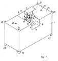
- the filling container consists of a cuboid container 1, from the filling chamber 2 of which a chamber 3 is separated in the upper part by a transverse U-shaped insert.
- the chamber 3 is open on the top and front and back. Its front and top opening can be closed by a first angular cover 4, which is articulated upwards in a first hinge joint 5.
- the chamber 3 is also closed by a second cover 6, which can also be pivoted upwards by a hinge joint 7.
- a guide rail 9 is mounted on the bottom 8, on which the bottle 10 to be filled is guided horizontally.
- a carriage 11 is attached, through which a filler neck holder 12 can be moved vertically when the cover 4 is pivoted upward, as shown in FIGS. 1 and 2.
- the filler neck holder 12 holds a filler neck 13, which is connected via a flexible line 14 to the pressure side of a rotary lobe pump.
- the pump 15 and an electric motor 16 coupled to it are mounted on the floor 8 in the rear part of the chamber 3.
- a control part 17 is fixedly mounted on the side wall of the chamber 3. It is connected on the one hand to the motor 16 and on the other hand via the cable 18 to the chassis 11.
- a signal transmitter 19 is arranged in the form of a mechanical switch which, when contacted by the bottle 10, starts the filling cycle.
- An immersion tube 20 is connected to the suction-side nozzle of the pump 15, which extends vertically through the base 8 into the filling space and is equipped with a foot valve 21 near the lower end.
- the dip tube 20 ends close above the bottom of the filling space, so that it can be substantially completely emptied.
- the filling space 2 can be filled through the connecting piece 22 in the ceiling wall 24.
- the bottling container has four angular feet 23 on the underside, which are set back somewhat from the side walls of the container. At the corners of the filling container, the top 24 protruding foot holders 25 are formed on top, whereby the stackability is improved and the stacking safety is increased.
- the filling container according to the invention has, for example, a base area dimension of 800 mm x 1200 mm and a height including the feet 23 of 1100 mm, the foot height being 100 mm.
- An opening may be provided in the bottom (not shown) to facilitate complete emptying and cleaning.
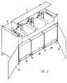
- FIG. 3 and 4 The embodiment of the shown in Figures 3 and 4 Filling container according to the invention differs from the container according to Figures 1 and 2 essentially in that it does not contain a filling and pumping device, but three such devices side by side. This filling container is therefore suitable for filling three different liquids from one supplier.
- Each filling and pumping station is assigned an exchange tank 26 which is inserted into the filling space 2 of the container 1.
- the exchange tank 26 contains a recessed filler neck 27 on the upper side, to which in turn an immersion tube 20 with a foot valve 21 is connected.
- a flexible pipe section 28 is connected to the suction side of the pump 15, the lower end of which carries a coupling part 29 which can be screwed tightly to the filler neck 27 of the exchange tank 26.
- two doors 30 pivotable to the side are articulated on the front, so that the filling space 2 is accessible for the use of the exchange tanks 26.
- the exchange tanks 26 have baseboards 31 (or feet) which enable the tanks to be moved into the filling space 2 with a forklift or the like.
- the second cover 6 is pivoted up around the joint. Since the base 8 has no sealing function in this embodiment, it is broken through between the pump units 15, 16 of the individual stations. When the cover 6 is folded up, the connection 27-29 is therefore accessible by hand so that the operator can connect the replacement tank 26.
- a lid 4 is provided for all three filling stations. It is also possible to provide separate lids for each filling station so that the stations that are not in operation can remain closed.
Landscapes
- Engineering & Computer Science (AREA)
- Mechanical Engineering (AREA)
- Filling Of Jars Or Cans And Processes For Cleaning And Sealing Jars (AREA)
Priority Applications (1)
| Application Number | Priority Date | Filing Date | Title |
|---|---|---|---|
| EP92110350A EP0574610A1 (fr) | 1992-06-19 | 1992-06-19 | Conteneur pour le transport de liquides à transferer dans des bouteilles |
Applications Claiming Priority (1)
| Application Number | Priority Date | Filing Date | Title |
|---|---|---|---|
| EP92110350A EP0574610A1 (fr) | 1992-06-19 | 1992-06-19 | Conteneur pour le transport de liquides à transferer dans des bouteilles |
Publications (1)
| Publication Number | Publication Date |
|---|---|
| EP0574610A1 true EP0574610A1 (fr) | 1993-12-22 |
Family
ID=8209726
Family Applications (1)
| Application Number | Title | Priority Date | Filing Date |
|---|---|---|---|
| EP92110350A Withdrawn EP0574610A1 (fr) | 1992-06-19 | 1992-06-19 | Conteneur pour le transport de liquides à transferer dans des bouteilles |
Country Status (1)
| Country | Link |
|---|---|
| EP (1) | EP0574610A1 (fr) |
Cited By (1)
| Publication number | Priority date | Publication date | Assignee | Title |
|---|---|---|---|---|
| CN111543323A (zh) * | 2020-05-29 | 2020-08-18 | 沭阳呈祥花卉研究开发有限公司 | 蝴蝶兰培养基灌装设备 |
Citations (7)
| Publication number | Priority date | Publication date | Assignee | Title |
|---|---|---|---|---|
| US2652174A (en) * | 1950-07-29 | 1953-09-15 | Union Metal Mfg Co | Tote box stack construction |
| US4819833A (en) * | 1988-01-25 | 1989-04-11 | Hudd Investment Trust, Inc. | Measuring, metering, and mixing can for gasoline and oil |
| US5005615A (en) * | 1990-01-08 | 1991-04-09 | Lrs, Inc. | Safety tank apparatus for liquid storage |
| DE9107528U1 (de) * | 1991-05-23 | 1991-10-10 | Armaturenfabrik Ernst Horn GmbH, 24937 Flensburg | Vorrichtung zur Abgabe geeichter Mengen von Flüssigkeiten für Kraftfahrzeuge |
| DE9112312U1 (de) * | 1991-10-02 | 1991-11-21 | Deutsche Tecalemit Gmbh, 4800 Bielefeld | Abgabeeinrichtung für Flüssigkeiten, insbesondere für Mineralölprodukte |
| DE9108409U1 (de) * | 1991-07-08 | 1991-12-05 | Contraves GmbH, 7768 Stockach | Vorrichtung zum Nachfüllen von Waschmitteln o.dgl. |
| DE9110046U1 (de) * | 1991-08-14 | 1991-12-19 | Boes, Hans Christian, Dipl.-Ing., 4650 Gelsenkirchen | Behälterkonzept |
-
1992
- 1992-06-19 EP EP92110350A patent/EP0574610A1/fr not_active Withdrawn
Patent Citations (7)
| Publication number | Priority date | Publication date | Assignee | Title |
|---|---|---|---|---|
| US2652174A (en) * | 1950-07-29 | 1953-09-15 | Union Metal Mfg Co | Tote box stack construction |
| US4819833A (en) * | 1988-01-25 | 1989-04-11 | Hudd Investment Trust, Inc. | Measuring, metering, and mixing can for gasoline and oil |
| US5005615A (en) * | 1990-01-08 | 1991-04-09 | Lrs, Inc. | Safety tank apparatus for liquid storage |
| DE9107528U1 (de) * | 1991-05-23 | 1991-10-10 | Armaturenfabrik Ernst Horn GmbH, 24937 Flensburg | Vorrichtung zur Abgabe geeichter Mengen von Flüssigkeiten für Kraftfahrzeuge |
| DE9108409U1 (de) * | 1991-07-08 | 1991-12-05 | Contraves GmbH, 7768 Stockach | Vorrichtung zum Nachfüllen von Waschmitteln o.dgl. |
| DE9110046U1 (de) * | 1991-08-14 | 1991-12-19 | Boes, Hans Christian, Dipl.-Ing., 4650 Gelsenkirchen | Behälterkonzept |
| DE9112312U1 (de) * | 1991-10-02 | 1991-11-21 | Deutsche Tecalemit Gmbh, 4800 Bielefeld | Abgabeeinrichtung für Flüssigkeiten, insbesondere für Mineralölprodukte |
Cited By (1)
| Publication number | Priority date | Publication date | Assignee | Title |
|---|---|---|---|---|
| CN111543323A (zh) * | 2020-05-29 | 2020-08-18 | 沭阳呈祥花卉研究开发有限公司 | 蝴蝶兰培养基灌装设备 |
Similar Documents
| Publication | Publication Date | Title |
|---|---|---|
| DE69606919T2 (de) | Tupferausgabevorrichtung | |
| EP4728957A2 (fr) | Cartouche pour agent de traitement pour lave-vaisselle et lave-vaisselle | |
| DE10100133B4 (de) | Transport-und Lagerbehälter für Flüssikeiten | |
| DE8805448U1 (de) | Ständer für Pipettenspitzen | |
| EP2794410B1 (fr) | Bidon empilable | |
| DE69615625T2 (de) | Zusammengesetzte verpackung für auslöffelbare produkte | |
| EP0574610A1 (fr) | Conteneur pour le transport de liquides à transferer dans des bouteilles | |
| DE9208181U1 (de) | Abfüllcontainer | |
| DE4327442A1 (de) | Faß, das besonders zum Versenden von Chemikalien oder Abfällen geeignet ist | |
| DE3703911C2 (fr) | ||
| DE102008030076A1 (de) | Verbundstoffverpackung für flüssiges oder viskoses Füllgut | |
| DE4041748C2 (fr) | ||
| EP0610489B1 (fr) | Recipient de transport reutilisable | |
| DE202008012489U1 (de) | Behälter zur Aufnahme von gleichartigen Gegenständen | |
| DE19957716C2 (de) | Verfahren und Vorrichtung zum Ent- und Versorgen mit Hilfe von verschließbaren Behältern | |
| EP0789660B1 (fr) | Caisse de transport | |
| DE3621833A1 (de) | Stapelbarer kunststoffbehaelter | |
| DE9404654U1 (de) | Mehrwegbehälter aus Kunststoff | |
| DE29701733U1 (de) | Wasch- und Geschirrspülmitteltabletten-Behälter | |
| EP3964422B1 (fr) | Chariot permettant de recevoir au moins un récipient de transport | |
| DE29515715U1 (de) | Kunststoff-Kanister | |
| EP0640556A1 (fr) | Dispositif de remplissage | |
| DE4240670C2 (de) | Spender für Spülmittel, insbesondere für Industriespülmittel | |
| DE19817673A1 (de) | Palettencontainer | |
| DE8908787U1 (de) | Verpackung für fließfähiges Füllgut |
Legal Events
| Date | Code | Title | Description |
|---|---|---|---|
| PUAI | Public reference made under article 153(3) epc to a published international application that has entered the european phase |
Free format text: ORIGINAL CODE: 0009012 |
|
| AK | Designated contracting states |
Kind code of ref document: A1 Designated state(s): AT BE CH DE DK ES FR GB GR IT LI NL SE |
|
| STAA | Information on the status of an ep patent application or granted ep patent |
Free format text: STATUS: THE APPLICATION IS DEEMED TO BE WITHDRAWN |
|
| 18D | Application deemed to be withdrawn |
Effective date: 19940623 |