EP0574925B1 - Appareil récepteur à ultrasons et dispositif de détection d'obstacles - Google Patents
Appareil récepteur à ultrasons et dispositif de détection d'obstacles Download PDFInfo
- Publication number
- EP0574925B1 EP0574925B1 EP93109717A EP93109717A EP0574925B1 EP 0574925 B1 EP0574925 B1 EP 0574925B1 EP 93109717 A EP93109717 A EP 93109717A EP 93109717 A EP93109717 A EP 93109717A EP 0574925 B1 EP0574925 B1 EP 0574925B1
- Authority
- EP
- European Patent Office
- Prior art keywords
- ultrasonic wave
- elastic body
- rubber
- obstacle detection
- vehicle
- Prior art date
- Legal status (The legal status is an assumption and is not a legal conclusion. Google has not performed a legal analysis and makes no representation as to the accuracy of the status listed.)
- Expired - Lifetime
Links
Images





Classifications
-
- G—PHYSICS
- G01—MEASURING; TESTING
- G01S—RADIO DIRECTION-FINDING; RADIO NAVIGATION; DETERMINING DISTANCE OR VELOCITY BY USE OF RADIO WAVES; LOCATING OR PRESENCE-DETECTING BY USE OF THE REFLECTION OR RERADIATION OF RADIO WAVES; ANALOGOUS ARRANGEMENTS USING OTHER WAVES
- G01S15/00—Systems using the reflection or reradiation of acoustic waves, e.g. sonar systems
- G01S15/02—Systems using the reflection or reradiation of acoustic waves, e.g. sonar systems using reflection of acoustic waves
- G01S15/04—Systems determining presence of a target
-
- G—PHYSICS
- G01—MEASURING; TESTING
- G01S—RADIO DIRECTION-FINDING; RADIO NAVIGATION; DETERMINING DISTANCE OR VELOCITY BY USE OF RADIO WAVES; LOCATING OR PRESENCE-DETECTING BY USE OF THE REFLECTION OR RERADIATION OF RADIO WAVES; ANALOGOUS ARRANGEMENTS USING OTHER WAVES
- G01S15/00—Systems using the reflection or reradiation of acoustic waves, e.g. sonar systems
- G01S15/88—Sonar systems specially adapted for specific applications
- G01S15/93—Sonar systems specially adapted for specific applications for anti-collision purposes
- G01S15/931—Sonar systems specially adapted for specific applications for anti-collision purposes of land vehicles
-
- G—PHYSICS
- G01—MEASURING; TESTING
- G01H—MEASUREMENT OF MECHANICAL VIBRATIONS OR ULTRASONIC, SONIC OR INFRASONIC WAVES
- G01H11/00—Measuring mechanical vibrations or ultrasonic, sonic or infrasonic waves by detecting changes in electric or magnetic properties
- G01H11/06—Measuring mechanical vibrations or ultrasonic, sonic or infrasonic waves by detecting changes in electric or magnetic properties by electric means
-
- G—PHYSICS
- G01—MEASURING; TESTING
- G01S—RADIO DIRECTION-FINDING; RADIO NAVIGATION; DETERMINING DISTANCE OR VELOCITY BY USE OF RADIO WAVES; LOCATING OR PRESENCE-DETECTING BY USE OF THE REFLECTION OR RERADIATION OF RADIO WAVES; ANALOGOUS ARRANGEMENTS USING OTHER WAVES
- G01S7/00—Details of systems according to groups G01S13/00, G01S15/00, G01S17/00
- G01S7/52—Details of systems according to groups G01S13/00, G01S15/00, G01S17/00 of systems according to group G01S15/00
- G01S7/521—Constructional features
-
- G—PHYSICS
- G01—MEASURING; TESTING
- G01S—RADIO DIRECTION-FINDING; RADIO NAVIGATION; DETERMINING DISTANCE OR VELOCITY BY USE OF RADIO WAVES; LOCATING OR PRESENCE-DETECTING BY USE OF THE REFLECTION OR RERADIATION OF RADIO WAVES; ANALOGOUS ARRANGEMENTS USING OTHER WAVES
- G01S15/00—Systems using the reflection or reradiation of acoustic waves, e.g. sonar systems
- G01S15/88—Sonar systems specially adapted for specific applications
- G01S15/93—Sonar systems specially adapted for specific applications for anti-collision purposes
- G01S15/931—Sonar systems specially adapted for specific applications for anti-collision purposes of land vehicles
- G01S2015/937—Sonar systems specially adapted for specific applications for anti-collision purposes of land vehicles sensor installation details
- G01S2015/938—Sonar systems specially adapted for specific applications for anti-collision purposes of land vehicles sensor installation details in the bumper area
Definitions
- This invention relates to an ultrasonic wave reception apparatus and an obstacle detection apparatus utilizing the same.
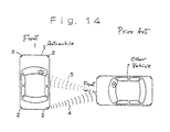
- an automobile 1 with an obstacle detection apparatus which has a case 2 containing an ultrasonic wave transmitter and a receiver disposed at a corner part 3 of the vehicle body for preventing collision at the corner during garaging or the like.
- An ultrasonic wave 4 is transmitted from the corner part 3 and its reflection wave 5 is received to determine the distance from the corner part 3 to an obstacle 6 based upon the delay time from the transmission to the reception and notify the driver of the distance.
- An piezoelectric element is used for the transmission and reception of the ultrasonic wave.
- an ultrasonic wave is a compression wave of air
- the piezoelectric element receives the compression wave to produce a deformation, and the deformation generates an electromotive force by the piezoelectric effect of the element.
- a piezoelectric element is used as an ultrasonic wave reception sensor, since the piezoelectric element itself has a natural frequency, and it is necessary to select a specific resonance frequency region by selecting its material, size, and shape in order to improve the sensitivity, it is difficult to receive ultrasonic wave 5 over a wide frequency region.
- the transmitter and the receiver have a substantial directional dependency.
- the above-described prior art obstacle detection apparatus is effective for preventing collision of the corner part 3.
- an obstacle for example, another automobile 7, is present at the right or left of the automobile 1, it may sometimes be impossible to receive the reflection wave 5 and detect the other vehicle 7.
- it has been considered to provide the transmitter and receiver not only at the corner part 3, but as disclosed in Japanese Utility Model Laid-open Publication 63-69654, a number of the devices may be provided over the entire periphery of the vehicle.
- the piezoelectric element is increased in length to expand the reception zone, the resonance frequency is decreased to the extent, and not resonant with nor receive the ultrasonic wave, which is not practical.
- the danger of collision with an obstacle depends not only on the distance but also on the relative velocity with the obstacle.
- the prior art obstacle detection apparatus which uses a piezoelectric element, it is difficult to measure the relative velocity.
- the frequency of the reflection wave may be out of the resonance frequency of the reception piezoelectric element, and the reflection wave is not detected.
- a primary object of the present invention is to provide an apparatus which is able to receive an ultrasonic wave without being affected by a change in frequency and therefore receive an ultrasonic wave in all directions.
- an ultrasonic wave reception apparatus comprising a rubber-like elastic body interspersed with electroconductive particles, and conversion means for applying a voltage to the rubber-like elastic body to obtain an ultrasonic wave reception signal from a change in electrical resistance.
- the electroconductive particles interspersed in the rubber-like elastic body vibrate and undergo relative dislocation due to the vibration of the ultrasonic wave, which leads to a change in electrical resistance characteristics of the rubber-like elastic body.
- an electrical signal varying according to a change in electrical resistance is obtained, and the electrical signal varies with the ultrasonic vibration.
- the rubber-like elastic body utilizes the changes in electrical resistance characteristics due to relative dislocation between the electroconductive particles interspersed therein, and is therefore not affected by a particular natural frequency as typically seen in a piezoelectric element, and thereby receives the ultrasonic wave over a wide frequency range without being affected by the size and shape of the element.
- a relatively long-sized rubber-like elastic body can receive an ultrasonic wave.
- reception is also possible even if the frequency varies due to the Doppler effect.
- the rubber-like elastic body along an outer periphery almost over the entire periphery of its support member. This enables the ultrasonic wave to be received from any direction without disturbance by the support member.
- the electroconductive particles are preferably carbon short fibers of 0.01 to 0.02 mm in diameter and less than 1 mm in length, or carbon particles of 0.01 to 0.1 mm in diameter, contained in an amount of 25% to 60% by weight based on the total weight of the rubber-like elastic body. In this case, a sufficient conductivity and a sufficient strength of the rubber-like elastic body can be achieved.
- an obstacle detection apparatus comprising an ultrasonic wave transmission apparatus mounted on a support member for transmitting an ultrasonic wave outward, a rubber-like elastic body interspersed with electroconductive particles provided on an outer surface of the support member, and conversion means for applying a voltage to the rubber-like elastic body to obtain an ultrasonic wave reception signal from a change in electrical resistance.
- an ultrasonic wave is transmitted outward, and its reflection wave is received by the rubber-like elastic body, which converts the wave to an electrical signal to detect an obstacle.
- the obstacle detection apparatus is provided with distance calculation means for calculating a distance to a reflective body from a difference between the time at which the ultrasonic wave is transmitted from the ultrasonic wave transmission apparatus and the time at which the wave is received by the rubber-like elastic body.
- the distance between the support member and the reflective body is calculated from the difference in time between transmission and reception of the ultrasonic wave.
- the obstacle detection apparatus further comprises relative velocity calculation means for calculating a relative velocity between the support member and the reflective body from a difference in frequency between the ultrasonic wave transmitted from the transmission apparatus and the ultrasonic wave received by the rubber-like elastic body.
- the obstacle detection apparatus may also include collision time calculation means for calculating a time to collision of the support member with the reflective body from the relative velocity and the distance calculated by the distance calculation means. In this case, utilizing the Doppler effect, a relative velocity between the support member and the reflective body is calculated from a difference in frequency between the transmitted ultrasonic wave and the received ultrasonic wave, and a time to collision is calculated from the relative velocity and the distance.
- another obstacle detection apparatus comprising an ultrasonic wave transmission apparatus mounted on a vehicle for transmitting an ultrasonic wave outward, a rubber-like elastic body interspersed with electroconductive particles provided on an outer surface of the vehicle, and conversion means for applying a voltage to the rubber-like elastic body to obtain an ultrasonic wave reception signal from a change in electrical resistance.
- an ultrasonic wave is transmitted outward, and its reflection wave is received by the rubber-like elastic body, which wave is converted to an electrical signal to detect an obstacle.
- the obstacle detection apparatus is provided with distance calculation means for calculating a distance to a reflective body from a difference between the time at which the ultrasonic wave is transmitted from the ultrasonic wave transmission apparatus and the time at which the wave is received by the rubber-like elastic body.
- the distance between the vehicle and the reflective body is calculated from the difference in time between transmission and reception of the ultrasonic wave.
- the obstacle detection apparatus further comprises relative velocity calculation means for calculating a relative velocity between the vehicle and the reflective body from a difference in frequency between the ultrasonic wave transmitted from the transmission apparatus and the ultrasonic wave received by the rubber-like elastic body.
- the apparatus may also include collision time calculation means for calculating a time to collision of the vehicle with the reflective body from the relative velocity and the distance calculated by the distance calculation means.
- a relative velocity between the vehicle and the reflective body is calculated from a difference in frequency between the transmitted ultrasonic wave and the received ultrasonic wave, and a time to collision is calculated from the relative velocity and the distance,
- the rubber-like elastic body may be provided on the entire outer periphery of the vehicle or at a selected portion of the outer surface of the vehicle. Furthermore, the rubber-like elastic body may be mounted on an indicator provided on the roof. A selected portion of the outer surface of the vehicle is preferably at least one of the front and rear bumpers, doors, wheel arches, fenders, and body panels of the vehicle. Furthermore, portions of the rubber-like elastic body can be electrically connected in series or parallel.
- the ultrasonic wave can be received from all directions when the rubber-like elastic body is provided over the entire outer periphery of the vehicle body, or the ultrasonic wave from a selected zone can be received when the rubber-like elastic body is provided at a selected position.
- the rubber-like elastic body is provided in segments in selected portions, it can satisfactorily receive the ultrasonic wave by connecting the segments or pieces electrically in series. Alternatively, the pieces may be electrically connected in parallel and the individual pieces be applied with a voltage. All of the ultrasonic wave reception signals can be processed by a single obstacle detection apparatus.
- the ultrasonic wave transmitters may be attached to the four individual corner parts, or a single transmitter may be mounted on the roof of the vehicle.
- a single non-directional ultrasonic wave transmitter can be provided on the roof, or directional ultrasonic wave transmission means can be provided at four corner parts of the vehicle, to transmit and receive the ultrasonic wave over the entire outer periphery of the vehicle body.
- the invention includes air bag operation instruction means for operating an air bag when the time to collision calculated by the collision time calculation means is less than a predetermined value.
- the invention may include air bag operation permission means for permitting the operation of the air bag only when the relative velocity calculated by the relative velocity calculation means is greater than a predetermined value.
- Another feature of the invention comprises warning means for giving different warnings according to the time to collision calculated by the collision time calculation means. In these cases, since, when the support member is a vehicle, it is difficult to avoid collision if the time to collision is short, the air bag is operated to protect the passenger. The air bag is operated only when the relative velocity is high, and the air bag is not operated since the shock is very small when the relative velocity is low. Furthermore, different warnings are given according to the time to collision to attract the driver's attention.
- Another obstacle detection apparatus comprises an ultrasonic wave transmission apparatus mounted on the vehicle for transmitting an ultrasonic wave outward, a molding formed of a rubber-like elastic body interspersed with electroconductive particles, and conversion means for applying a voltage to the rubber-like elastic body of the molding to obtain an ultrasonic wave reception signal from a change in electrical resistance.
- an existing molding can also be used as the rubber-like elastic body, thereby eliminating the need for a new place for the rubber-like elastic body.
- the molding may be a side protect molding or a bumper molding of the vehicle.
- the present invention it is possible to provide an apparatus which can receive ultrasonic waves without being affected by the resonance frequency and even in the presence of the Doppler effect.
- the apparatus can be provided with a desired size necessary for a desired range, and may be an apparatus which can detect an obstacle in all directions.
- the present invention can accurately detect an approaching obstacle, it remarkably improves safety when used for the vehicle.
- an air bag is practically of no use if the air bag is opened after a collision.
- the air bag can be previously operated to reduce injury to the passenger.
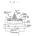
- Fig.1 is a schematic view showing an arrangement of a basic embodiment of the ultrasonic wave reception apparatus according to the present invention.
- Fig.2(a) is a diagram showing a waveform example of ultrasonic wave reception.
- Fig.2(b) is a diagram showing a waveform example when an ultrasonic wave from a fixed position is received.
- Fig,2(c) is a diagram showing a waveform example when an ultrasonic wave from an object approaching at a constant speed is received.
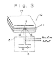
- Fig.3 is a schematic view showing an embodiment of the ultrasonic wave reception apparatus of the invention.
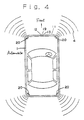
- Fig.4 is a schematic view showing a first embodiment of automobile to which the obstacle detection apparatus of the present invention is applied.
- Fig.5 is diagram showing the circuit construction of the first embodiment of the obstacle detection apparatus.
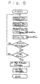
- Fig.6 is a flow chart showing operation of the obstacle detection apparatus.
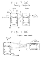
- Fig.7(a) is a schematic view showing a condition where the vehicle and an obstacle are traveling side by side.
- Fig.7(b) is a schematic view showing a condition where an obstacle is about to collide with the side of the vehicle.
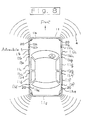
- Fig.8 is a schematic view showing a second embodiment of automobile to which the obstacle detection apparatus of the present invention is applied.
- Fig.9 is diagram showing the circuit construction of the second embodiment of the obstacle detection apparatus.
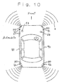
- Fig.10 is a schematic view showing a third embodiment of automobile to which the obstacle detection apparatus of the present invention is applied.
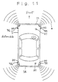
- Fig.11 is a schematic view showing a fourth embodiment of automobile to which the obstacle detection apparatus of the present invention is applied.
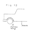
- Fig.12 is a schematic view showing a wheel house molding formed of the rubber-like elastic body.
- Fig.13 is a schematic view of a prior art obstacle detection apparatus.
- Fig.14 is a schematic view showing a prior art problem.
- Fig.15 is a schematic view showing a further embodiment wherein the rubber-like elastic body is mounted to an indicator on the roof.
- Fig.1 shows the basic structure of an ultrasonic wave reception apparatus 10.
- a rubber-like elastic body 11 is formed of a substance 11A having a rubber elasticity, including elastic rubber or rubber-like substances such as synthetic rubber, plastics, or resins, interspersed with electroconductive particles 11B.
- the electroconductive particles 11B include short fibers, for example, carbon and metal particles of silver, copper, or the like.
- the content of the electroconductive particles 11B may be such that both the electroconductivity and the rubber strength are assured. For example, when carbon is used, the content is preferably 25% to 60% by weight.
- the shape of the carbon particles can be particles of 0.01 to 0.1 mm in diameter, or fibers of 0.01 to 0.02 in diameter and less than 1 mm in length.
- electrodes 12 and 13 are formed at both ends of an elongated rubber-like elastic body 11 with a thickness of 0.5 to 1.0 mm.
- the elastic body is mounted on an insulating support member 14, and a DC power supply 16 is connected as a conversion circuit 15 between the electrodes 12 and 13 through a resistor R.
- a measuring instrument 17 such as an oscilloscope is connected between the electrodes 12 and 13.
- an ultrasonic wave 18 is applied, a waveform as shown in Fig.2(a) is observed, and the ultrasonic wave 18 could be received.
- the ultrasonic wave 18 in this case is a 175 KHz pulse wave.
- Fig.3 shows an embodiment wherein the rubber-like elastic body 11 is provided one fully turn around the outer periphery of the support member 14 so that reception is possible from anywhere in 360° around the support member 14, and an insulating material 19 is disposed between the electrodes 12 and 13.
- the numeral 15 indicates a conversion circuit.
- FIG.4 A first embodiment of obstacle detection apparatus of the present invention applied to an automobile will be described with reference to Figs.4 to 7.
- the elongated rubber-like elastic body 11 of the same shape as a body molding is provided continuously on the entire periphery over the front, rear, right and left surfaces of the automobile 1 so that it also functions as a molding, and the electrodes 12 and 13 are connected to the conversion circuit 15.
- the numeral 19 indicates the insulating material between the electrodes 12 and 13.
- ultrasonic wave transmitters 20 are attached to the four individual corner parts of the automobile 1 so that the ultrasonic wave 4 is transmitted outward radially.
- Fig.5 shows an example of circuit structure.
- the numeral 21 indicates an amplifier
- the numeral 22 indicates a detector
- the numeral 23 indicates a low-pass filter
- the numeral 24 indicates a distance calculator
- the numeral 25 indicates a pulse generator
- the numeral 26 indicates a relative velocity calculator
- the numeral 27 indicates a collision time calculator
- the numeral 28 indicates an air bag operation instructor
- the numeral 29 indicates an air bag operation permitter
- the numeral 30 indicates a warning device
- the numeral 31 indicates an actuator
- the numeral 32 indicates an air bag
- the numeral 33 indicates a buzzer.
- the individual devices 24 to 30 each comprise a microcomputer. The functions will be described below.
- the ultrasonic wave transmitter 20 transmits the ultrasonic wave 4 of a preset frequency intermittently for a preselected time every time the pulse generator 25 generates a pulse.
- the ultrasonic wave receiver 10 receives a reflection wave 5.
- the reception signal is amplified by the amplifier 21, detected by the detector 22, and passed through the low-pass filter 23 to be shaped to a reception pulse signal.
- the reception signal of the ultrasonic wave receiver 10 is also inputted to the relative velocity calculator 26 through the amplifier 21, where a frequency fR of the reception signal is detected.
- a positive relative velocity VX indicates that the obstacle is approaching.
- the warning device 30 in order to notify the passenger of the condition before the air bag operation, divides the collision time into a plurality of intervals or segments in length to sound the buzzer 33 stepwise with a higher tone for a shorter collision time T. However, when T is sufficiently long, the buzzer 33 is not sounded.
- the value of distance L and the magnitude of the relative velocity VX are divided into a plurality of segments or levels to notify the passenger of the distance and the relative velocity with different indication colors.
- the air bag for lateral collision will not serve the purpose if it opens after collision.
- the first embodiment is described for a structure in which the rubber-like elastic body also functions as a molding.
- the rubber-like elastic body may also be attached to an existing molding by an adhesive or the like, or provided on the vehicle body surface separately from the molding, with no problem.
- a single non-directional transmitter 20 may be mounted on the roof.
- Electrodes 12a to 12h and 13a to 13h are connected to the individual conversion circuits 15a to 15h, and independently applied with voltages.
- the individual electrodes 12a to 12h and 13a to 13h are insulated from adjacent electrodes by insulating materials or spaces.
- the ultrasonic wave transmitters 20 are attached to the four individual corner parts of the automobile 1 so that the ultrasonic wave 4 is transmitted outward radially.
- the circuit construction is common for the portion after the amplifier 21 as shown in Fig.5 and, as shown in Fig.9, the individual outputs of the conversion circuits 15a to 15h connected with the electrodes 12a to 12h and 13a to 13h of the individual rubber-like elastic bodies 11a to 11h are inputted in parallel to the amplifier 21.
- the rubber-like elastic bodies may be connected in series. The operation is the same as described in the first embodiment.
- the rubber-like elastic bodies may be attached to existing moldings, or attached to the vehicle body surface separately from the moldings, with no problem.
- the rubber-like elastic body 11 may be attached to an indicator 59 provided on a roof 58 of a taxi or the like.
- a single transmitter 20 of a non-directional type may be provided on the roof with no problem.
- a third embodiment of the obstacle detection apparatus according to the present invention will now be described.
- side protect moldings 50 formed of the rubber-like elastic body interspersed with electroconductive particles are mounted on the right and left side surfaces of the automobile 1, and electrodes 51 and 52 are connected to conversion circuits 53. Furthermore, ultrasonic wave transmitters 20 are mounted to the individual four corner parts of the automobile 1 so that the ultrasonic wave 4 is transmitted outward radially.
- the circuit construction is common for the portion after the amplifier 21 as shown in Fig.5, and outputs of the conversion circuits 53 connected with the electrodes 51 and 52 of the individual side protect moldings 50 are inputted in parallel to the amplifier 21.
- the individual side protect moldings may be electrically connected in series. The operation is the same as described in the first embodiment.
- a single transmitter 20 of a non-directional type may be provided on the roof with no problem.
- front and rear bumpers having bumper moldings 54 formed of the rubber-like elastic body interspersed with electroconductive particles are mounted on the front and rear of the automobile 1, and electrodes 55 and 56 are connected to conversion circuits 57.
- ultrasonic wave transmitters, 20 are mounted to the individual four corner parts of the automobile 1 so that the ultrasonic wave 4 is transmitted outward radially.
- the circuit construction is common for the portion after the amplifier 21 as shown in Fig.5, and outputs of the conversion circuits 57 connected with the electrodes 55 and 56 of the individual bumper moldings 54 are inputted in parallel to the amplifier 21.
- the individual bumper moldings may be electrically connected in series. The operation is the same as described in the first embodiment.
- a single transmitter 20 of a non-directional type may be provided on the roof with no problem.
- the individual moldings formed of the rubber-like elastic body described in the third and fourth embodiments may be appropriate ones which are attached to the vehicle body, and may be used for wheel house moldings 60 as shown in Fig.12, for example. Needless to say, the attached individual moldings may be electrically connected in series or parallel. In this case, the portion after the amplifier 21 may be a single unit.
Landscapes
- Engineering & Computer Science (AREA)
- Physics & Mathematics (AREA)
- Radar, Positioning & Navigation (AREA)
- Remote Sensing (AREA)
- General Physics & Mathematics (AREA)
- Computer Networks & Wireless Communication (AREA)
- Acoustics & Sound (AREA)
- Measurement Of Velocity Or Position Using Acoustic Or Ultrasonic Waves (AREA)
- Measurement Of Mechanical Vibrations Or Ultrasonic Waves (AREA)
- Air Bags (AREA)
- Control Of Driving Devices And Active Controlling Of Vehicle (AREA)
Claims (23)
- Appareil de réception d'ondes ultrasonores, comprenant des moyens pour détecter la réception d'une onde ultrasonore, caractérisé en ce que lesdits moyens pour détecter la réception d'une onde ultrasonore comprennent un corps élastique analogue au caoutchouc (11) dans lequel sont dispersées des particules électroconductrices (11B), et des moyens pour appliquer une tension audit corps élastique analogue au caoutchouc et pour produire un signal de réception d'onde ultrasonore (18) depuis un changement dans la résistance électrique dudit corps élastique.
- Appareil de réception d'ondes ultrasonores selon la revendication 1, comprenant en outre un élément de support (14) pour ledit corps élastique analogue au caoutchouc (11), dans lequel ledit corps élastique analogue au caoutchouc est prévu sensiblement le long de la périphérie entière dudit élément de support.
- Appareil de réception d'ondes ultrasonores selon la revendication 1, dans lequel les particules électroconductrices (11B) sont en carbone et contenues dans une quantité allant de 25 à 60% en poids en se basant sur le poids total dudit corps élastique analogue au caoutchouc (11).
- Appareil de réception d'ondes ultrasonores selon la revendication 1, dans lequel les particules électroconductrices (11B) sont en carbone sous la forme de fibres courtes de 0,01 à 0,02 mm de diamètre et de moins de 1 mm de longueur.
- Appareil de réception d'ondes ultrasonores selon la revendication 1, dans lequel les particules électroconductrices (11B) sont en carbone sous la forme de particules de 0,01 à 0,1 mm de diamètre.
- Appareil de détection d'obstacle comprenant un appareil d'émission d'onde ultrasonore et des moyens pour détecter la réception d'une onde ultrasonore, caractérisé en ce que :ledit appareil de détection d'obstacle comprend en outre un élément de support, un corps élastique analogue au caoutchouc dans lequel sont dispersées des particules électroconductrices, et des moyens pour appliquer une tension audit corps élastique analogue au caoutchouc pour obtenir un signal de réception d'onde ultrasonore depuis un changement dans la résistance électrique dudit corps élastique ; etledit appareil d'émission d'onde ultrasonore est monté sur ledit élément de support (14) pour émettre une onde ultrasonore (18) vers l'extérieur, et ledit corps élastique analogue au caoutchouc étant prévu le long d'une surface extérieure dudit élément de support.
- Appareil de détection d'obstacle selon la revendication 6, comprenant en outre des moyens de calcul de distance pour calculer une distance entre ledit élément de support (14) et un corps réflecteur à partir d'une différence entre un temps auquel une onde ultrasonore est émise depuis ledit appareil d'émission d'onde ultrasonore et un temps auquel l'onde ultrasonore réfléchie par le corps réflecteur est reçue par ledit corps élastique analogue au caoutchouc (11).
- Appareil de détection d'obstacle selon la revendication 7, comprenant en outre des moyens de calcul de vitesse relative pour calculer une vitesse relative entre ledit élément de support et le corps réflecteur à partir d'une différence de fréquences entre l'onde ultrasonore émise depuis ledit appareil d'émission et l'onde ultrasonore réfléchie par le corps réflecteur et reçue par ledit corps élastique analogue au caoutchouc, et des moyens de calcul de temps de collision afin de calculer un temps jusqu'à la collision dudit élément de support avec le corps réflecteur à partir de la vitesse relative et de la distance calculée par lesdits moyens de calcul de distance.
- Appareil de détection d'obstacle selon l'une des revendications précédentes, qui comprend un appareil d'émission d'onde ultrasonore monté sur un véhicule afin d'émettre une onde ultrasonore vers l'extérieur, un corps élastique analogue au caoutchouc, dans lequel sont dispersées des particules électroconductrices, prévu sur une surface extérieure du véhicule, et des moyens pour appliquer une tension audit corps élastique analogue au caoutchouc afin d'obtenir un signal de réception d'onde ultrasonore depuis un changement dans la résistance électrique dudit corps élastique.
- Appareil de détection d'obstacle selon la revendication 9, comprenant en outre des moyens de calcul de distance pour calculer une distance entre ledit véhicule et un corps réflecteur à partir d'une différence entre un temps auquel l'onde ultrasonore est émise depuis ledit appareil d'émission d'onde ultrasonore et un temps auquel l'onde réfléchie par le corps réflecteur est reçue par ledit corps élastique analogue au caoutchouc.
- Appareil de détection d'obstacle selon la revendication 10, comprenant en outre des moyens de calcul de vitesse relative pour calculer une vitesse relative entre ledit véhicule et le corps réflecteur à partir d'une différence de fréquences entre l'onde ultrasonore émise depuis ledit appareil d'émission et l'onde ultrasonore réfléchie par le corps réflecteur et reçue par ledit corps élastique analogue au caoutchouc, et des moyens de calcul de temps de collision pour calculer un temps jusqu'à la collision dudit véhicule avec le corps réflecteur à partir de la vitesse relative et de la distance calculée par lesdits moyens de calcul de distance.
- Appareil de détection d'obstacle selon la revendication 11, comprenant en outre des moyens d'instruction de fonctionnement pour coussin d'air afin de faire fonctionner un coussin d'air associé au véhicule lorsque le temps jusqu'à la collision calculé par lesdits moyens de calcul de temps de collision est inférieur à une valeur prédéterminée.
- Appareil de détection d'obstacle selon la revendication 11, comprenant en outre des moyens de permission de fonctionnement de coussin d'air afin de permettre le fonctionnement d'un coussin d'air associé au véhicule uniquement lorsque la vitesse relative calculée par lesdits moyens de calcul de vitesse relative est supérieure à une valeur prédéterminée.
- Appareil de détection d'obstacle selon la revendication 11, comprenant en outre des moyens d'avertissement pour avertir une collision du véhicule avec un objet réflecteur, dans lequel la forme de l'avertissement varie selon le temps jusqu'à la collision calculé par lesdits moyens de calcul de temps de collision.
- Appareil de détection d'obstacle selon la revendication 9, dans lequel ledit corps élastique analogue au caoutchouc est prévu sur la périphérie entière de la surface extérieure du véhicule.
- Appareil de détection d'obstacle selon la revendication 9, dans lequel ledit corps élastique analogue au caoutchouc est prévu sur une partie prédéterminée de la surface extérieure du véhicule.
- Appareil de détection d'obstacle selon la revendication 16, dans lequel ladite partie prédéterminée comprend au moins l'une des parties parmi le pare-chocs avant et le pare-chocs arrière, les portes, les passages de roues, les ailes, et les panneaux de carrosserie du véhicule.
- Appareil de détection d'obstacle selon la revendication 16, dans lequel ledit corps élastique analogue au caoutchouc comprend une pluralité de parties de carrosserie qui sont connectées électriquement en série ou en parallèle.
- Appareil de détection d'obstacle selon la revendication 9, dans lequel ledit corps élastique analogue au caoutchouc est attaché à un indicateur prévu sur un toit de la carrosserie du véhicule.
- Appareil de détection d'obstacle selon la revendication 9, dans lequel ledit appareil d'émission d'onde ultrasonore comprend des émetteurs individuels au niveau de quatre parties de coin du véhicule, ou bien un émetteur unique sur le toit du véhicule.
- Appareil de détection d'obstacle selon l'une des revendications précédentes, comprenant un appareil d'émission d'onde ultrasonore monté sur un véhicule pour émettre une onde ultrasonore vers l'extérieur, un élément moulé formé d'un corps élastique analogue au caoutchouc dans lequel sont dispersées des particules électroconductrices et associé aux véhicules, et des moyens pour appliquer une tension audit corps élastique analogue au caoutchouc de l'élément moulé pour obtenir un signal de réception d'onde ultrasonore à partir d'un changement dans la résistance électrique dudit corps élastique.
- Appareil de détection d'obstacle selon la revendication 21, dans lequel ledit élément moulé est un élément moulé de protection latérale du véhicule.
- Appareil de détection d'obstacle selon la revendication 21, dans lequel ledit élément moulé est un élément moulé formant pare-chocs du véhicule.
Applications Claiming Priority (2)
| Application Number | Priority Date | Filing Date | Title |
|---|---|---|---|
| JP159012/92 | 1992-06-18 | ||
| JP4159012A JPH063445A (ja) | 1992-06-18 | 1992-06-18 | 超音波受信装置及び障害物検知装置 |
Publications (3)
| Publication Number | Publication Date |
|---|---|
| EP0574925A2 EP0574925A2 (fr) | 1993-12-22 |
| EP0574925A3 EP0574925A3 (en) | 1994-08-10 |
| EP0574925B1 true EP0574925B1 (fr) | 1998-11-11 |
Family
ID=15684319
Family Applications (1)
| Application Number | Title | Priority Date | Filing Date |
|---|---|---|---|
| EP93109717A Expired - Lifetime EP0574925B1 (fr) | 1992-06-18 | 1993-06-17 | Appareil récepteur à ultrasons et dispositif de détection d'obstacles |
Country Status (5)
| Country | Link |
|---|---|
| US (1) | US5581232A (fr) |
| EP (1) | EP0574925B1 (fr) |
| JP (1) | JPH063445A (fr) |
| KR (1) | KR0151568B1 (fr) |
| DE (1) | DE69321997T2 (fr) |
Families Citing this family (37)
| Publication number | Priority date | Publication date | Assignee | Title |
|---|---|---|---|---|
| GB2289786B (en) * | 1994-05-23 | 1998-09-16 | Automotive Tech Int | Side impact airbag system with anticipatory sensor |
| US8041483B2 (en) | 1994-05-23 | 2011-10-18 | Automotive Technologies International, Inc. | Exterior airbag deployment techniques |
| US7783403B2 (en) | 1994-05-23 | 2010-08-24 | Automotive Technologies International, Inc. | System and method for preventing vehicular accidents |
| US7630806B2 (en) | 1994-05-23 | 2009-12-08 | Automotive Technologies International, Inc. | System and method for detecting and protecting pedestrians |
| JPH08122060A (ja) * | 1994-10-21 | 1996-05-17 | Mitsubishi Electric Corp | 車両周辺監視システム |
| JPH1069597A (ja) * | 1996-08-28 | 1998-03-10 | Toyota Motor Corp | 移動体の走行帯変更検出システム及びそのシステムに用いられる移動体検出器 |
| US5835007A (en) * | 1997-02-10 | 1998-11-10 | Delco Electronics Corporation | Method and apparatus for crash sensing using anticipatory sensor inputs |
| US5945907A (en) * | 1997-10-27 | 1999-08-31 | Michael Yaron | Apparatus and methods for parking a vehicle using position detection sensor |
| US6851504B2 (en) | 1998-12-14 | 2005-02-08 | Trw Vehicle Safety Systems Inc. | Method and apparatus for anticipating a vehicle crash event |
| US6678536B2 (en) * | 2000-12-07 | 2004-01-13 | Mark Wendell Fletcher | Wireless microphone |
| WO2003053748A1 (fr) * | 2001-12-06 | 2003-07-03 | Automotive Systems Laboratory, Inc. | Systeme de protection des occupants a airbag exterieur |
| US20040183661A1 (en) * | 2002-12-18 | 2004-09-23 | Bowman Timothy D. | Overhead obstacle detector for vehicles carrying roof top articles |
| US6957579B1 (en) * | 2002-12-23 | 2005-10-25 | The United States Of America As Represented By The Secretary Of The Navy | Cavity wall measurement apparatus and method |
| DE10358857A1 (de) * | 2003-12-16 | 2005-07-21 | Robert Bosch Gmbh | Abstandsmessvorrichtung zur Steuerung |
| JP2005219727A (ja) * | 2004-01-08 | 2005-08-18 | Denso Corp | 車両用衝突保護装置 |
| US8041469B2 (en) * | 2005-01-05 | 2011-10-18 | GM Global Technology Operations LLC | Determining relative spatial information between vehicles |
| US7688187B2 (en) * | 2005-11-07 | 2010-03-30 | Caird Andrew J | Early detection system and method for exterior vehicle cargo |
| US20070120707A1 (en) * | 2005-11-29 | 2007-05-31 | Rv Insite, Inc. | Method for positioning recreational vehicles and portable position sensor and alert system for recreational vehicles and other vehicles |
| DE102006032542A1 (de) * | 2006-07-13 | 2008-01-17 | Robert Bosch Gmbh | Verfahren zur Abstandsmessung und Ultraschallabstandssensor |
| JP4623435B2 (ja) * | 2008-01-16 | 2011-02-02 | トヨタ自動車株式会社 | 車両用乗員保護装置 |
| EP2151358B1 (fr) | 2008-08-08 | 2012-03-07 | Iveco S.p.A. | Procédé et dispositif pour assister le conducteur d'un véhicule en identifiant les obstacles à l'aide de capteurs d'ultrasons |
| JP5338829B2 (ja) | 2011-03-15 | 2013-11-13 | 株式会社デンソー | 運転支援装置 |
| JP5626132B2 (ja) * | 2011-06-07 | 2014-11-19 | 株式会社日本自動車部品総合研究所 | 物体検出装置 |
| US8887655B2 (en) | 2012-01-25 | 2014-11-18 | Honeywell International Inc. | Valve actuator with position indicator extension |
| CN102590814B (zh) * | 2012-03-02 | 2014-04-02 | 华南理工大学 | 一种超声波探头空间位置和三维姿态的检测装置及方法 |
| US9664409B2 (en) | 2012-06-14 | 2017-05-30 | Honeywell International Inc. | HVAC damper system |
| US10302207B2 (en) | 2012-06-14 | 2019-05-28 | Honeywell International Inc. | Spring loaded HVAC damper |
| US10119721B2 (en) | 2012-06-14 | 2018-11-06 | Honeywell International Inc. | Standoff for use with an insulated HVAC duct |
| US9423143B2 (en) | 2013-12-18 | 2016-08-23 | Honeywell International Inc. | HVAC actuator with light indicator |
| US9623523B2 (en) | 2013-12-18 | 2017-04-18 | Honeywell International Inc. | HVAC actuator with taping flange |
| US10941960B2 (en) | 2013-12-18 | 2021-03-09 | Ademco Inc. | HVAC actuator with position indicator |
| US9568207B2 (en) | 2013-12-18 | 2017-02-14 | Honeywell International Inc. | HVAC actuator with removable wire blocking tab |
| US9732980B2 (en) | 2013-12-18 | 2017-08-15 | Honeywell International Inc. | HVAC actuator with range adjustment |
| USD728071S1 (en) | 2013-12-27 | 2015-04-28 | Honeywell International Inc. | HVAC actuator |
| US9824589B1 (en) * | 2016-09-15 | 2017-11-21 | Ford Global Technologies, Llc | Vehicle collision risk detection |
| JP6874647B2 (ja) * | 2017-11-07 | 2021-05-19 | 株式会社デンソー | 送受信制御装置 |
| US10518806B1 (en) * | 2018-08-01 | 2019-12-31 | Ford Global Technologies, Llc | Ultrasonic locating |
Family Cites Families (12)
| Publication number | Priority date | Publication date | Assignee | Title |
|---|---|---|---|---|
| US2443471A (en) * | 1945-03-29 | 1948-06-15 | Bell Telephone Labor Inc | Piezoelectric damping means for mechanical vibrations |
| US2964272A (en) * | 1955-07-01 | 1960-12-13 | Rca Corp | Vibration control apparatus |
| US4142074A (en) * | 1957-10-29 | 1979-02-27 | The United States Of America As Represented By The Attorney General Of The United States | Microphone |
| US3464657A (en) * | 1967-08-30 | 1969-09-02 | Us Army | Vibration damped platform |
| US3703999A (en) * | 1969-12-12 | 1972-11-28 | Actron Ind Inc | Wide band stabilizer |
| US4674073A (en) * | 1985-02-28 | 1987-06-16 | Aisin Seiki Kabushiki Kaisha | Reflective object detecting apparatus |
| JPS6251061A (ja) * | 1985-08-30 | 1987-03-05 | Hitachi Ltd | 磁気テ−プ制御装置 |
| JPH0829592B2 (ja) * | 1986-09-11 | 1996-03-27 | セイコーエプソン株式会社 | インクジェット記録ヘッドのキャッピング方法 |
| US4795123A (en) * | 1987-05-14 | 1989-01-03 | The United States Of America As Represented By The Secretary Of The Air Force | Wideband electromagnetic damping of vibrating structures |
| US4849668A (en) * | 1987-05-19 | 1989-07-18 | Massachusetts Institute Of Technology | Embedded piezoelectric structure and control |
| US5261505A (en) * | 1990-03-05 | 1993-11-16 | Rolls-Royce Dsv Limited | Collision detector for a vehicle |
| DE9004394U1 (de) * | 1990-04-17 | 1990-08-09 | Josten, Wilhelm, 4100 Duisburg | Elastische Schiene |
-
1992
- 1992-06-18 JP JP4159012A patent/JPH063445A/ja not_active Withdrawn
-
1993
- 1993-06-17 DE DE69321997T patent/DE69321997T2/de not_active Expired - Fee Related
- 1993-06-17 EP EP93109717A patent/EP0574925B1/fr not_active Expired - Lifetime
- 1993-06-17 US US08/077,639 patent/US5581232A/en not_active Expired - Fee Related
- 1993-06-17 KR KR1019930011087A patent/KR0151568B1/ko not_active Expired - Fee Related
Also Published As
| Publication number | Publication date |
|---|---|
| DE69321997D1 (de) | 1998-12-17 |
| KR0151568B1 (ko) | 1998-12-15 |
| US5581232A (en) | 1996-12-03 |
| EP0574925A2 (fr) | 1993-12-22 |
| KR940005946A (ko) | 1994-03-22 |
| DE69321997T2 (de) | 1999-06-17 |
| JPH063445A (ja) | 1994-01-11 |
| EP0574925A3 (en) | 1994-08-10 |
Similar Documents
| Publication | Publication Date | Title |
|---|---|---|
| US5581232A (en) | Ultrasonic wave reception apparatus and obstacle detection apparatus | |
| US3842397A (en) | Ultrasonic distance detection for vehicles | |
| US5389912A (en) | Truck clearance anti-collision device | |
| US5554907A (en) | Vehicle speed measurement apparatus | |
| US6281786B1 (en) | Obstacle detection system for a vehicle | |
| EP0830266B1 (fr) | Systeme de detection d'obstacles pour vehicule effectuant une marche arriere | |
| US5485140A (en) | Vehicle obstacle detector and alarm system | |
| US20040183661A1 (en) | Overhead obstacle detector for vehicles carrying roof top articles | |
| US5263006A (en) | Device and process for detecting the presence of a vehicle by means of an ultrasonic device | |
| US20110241858A1 (en) | Vehicle-use object detection apparatus | |
| EP0708019A3 (fr) | Appareil pour la mesure de condition de surface | |
| Hosur et al. | Environmental awareness around vehicle using ultrasonic sensors | |
| JP2008292168A (ja) | 障害物近接判定装置および障害物近接判定方法 | |
| Sairam et al. | Intelligent mechatronic braking system | |
| US3681750A (en) | Object detection apparatus | |
| JPS62240890A (ja) | 車両用障害物検知装置 | |
| CN111554093A (zh) | 通行参考数据实时解析系统及方法 | |
| EP1664839A1 (fr) | Systeme facilitant le parcage | |
| GB2513929A (en) | Distance Measuring Alert Sensor for Vehicle | |
| JP3232163B2 (ja) | 車載用超音波センサ装置 | |
| DE3221935A1 (de) | Elektronisches kfz-abstandmessgeraet | |
| GB2112520A (en) | Vehicle manoeuvring aid | |
| GB2038132A (en) | Distance indicating system | |
| GB2112144A (en) | Detector | |
| JPH0399272A (ja) | 自動車の走行状態検出装置 |
Legal Events
| Date | Code | Title | Description |
|---|---|---|---|
| PUAI | Public reference made under article 153(3) epc to a published international application that has entered the european phase |
Free format text: ORIGINAL CODE: 0009012 |
|
| 17P | Request for examination filed |
Effective date: 19930917 |
|
| AK | Designated contracting states |
Kind code of ref document: A2 Designated state(s): AT BE CH DE DK ES FR GB GR IE IT LI LU MC NL PT SE |
|
| RBV | Designated contracting states (corrected) |
Designated state(s): DE FR GB |
|
| PUAL | Search report despatched |
Free format text: ORIGINAL CODE: 0009013 |
|
| AK | Designated contracting states |
Kind code of ref document: A3 Designated state(s): AT BE CH DE DK ES FR GB GR IE IT LI LU MC NL PT SE |
|
| 17Q | First examination report despatched |
Effective date: 19970311 |
|
| GRAG | Despatch of communication of intention to grant |
Free format text: ORIGINAL CODE: EPIDOS AGRA |
|
| GRAG | Despatch of communication of intention to grant |
Free format text: ORIGINAL CODE: EPIDOS AGRA |
|
| GRAH | Despatch of communication of intention to grant a patent |
Free format text: ORIGINAL CODE: EPIDOS IGRA |
|
| GRAH | Despatch of communication of intention to grant a patent |
Free format text: ORIGINAL CODE: EPIDOS IGRA |
|
| GRAA | (expected) grant |
Free format text: ORIGINAL CODE: 0009210 |
|
| AK | Designated contracting states |
Kind code of ref document: B1 Designated state(s): DE FR GB |
|
| REF | Corresponds to: |
Ref document number: 69321997 Country of ref document: DE Date of ref document: 19981217 |
|
| ET | Fr: translation filed | ||
| PLBE | No opposition filed within time limit |
Free format text: ORIGINAL CODE: 0009261 |
|
| STAA | Information on the status of an ep patent application or granted ep patent |
Free format text: STATUS: NO OPPOSITION FILED WITHIN TIME LIMIT |
|
| 26N | No opposition filed | ||
| REG | Reference to a national code |
Ref country code: GB Ref legal event code: IF02 |
|
| REG | Reference to a national code |
Ref country code: FR Ref legal event code: CA |
|
| PGFP | Annual fee paid to national office [announced via postgrant information from national office to epo] |
Ref country code: FR Payment date: 20060608 Year of fee payment: 14 |
|
| PGFP | Annual fee paid to national office [announced via postgrant information from national office to epo] |
Ref country code: GB Payment date: 20060614 Year of fee payment: 14 |
|
| PGFP | Annual fee paid to national office [announced via postgrant information from national office to epo] |
Ref country code: DE Payment date: 20060615 Year of fee payment: 14 |
|
| GBPC | Gb: european patent ceased through non-payment of renewal fee |
Effective date: 20070617 |
|
| REG | Reference to a national code |
Ref country code: FR Ref legal event code: ST Effective date: 20080229 |
|
| PG25 | Lapsed in a contracting state [announced via postgrant information from national office to epo] |
Ref country code: DE Free format text: LAPSE BECAUSE OF NON-PAYMENT OF DUE FEES Effective date: 20080101 |
|
| PG25 | Lapsed in a contracting state [announced via postgrant information from national office to epo] |
Ref country code: GB Free format text: LAPSE BECAUSE OF NON-PAYMENT OF DUE FEES Effective date: 20070617 |
|
| PG25 | Lapsed in a contracting state [announced via postgrant information from national office to epo] |
Ref country code: FR Free format text: LAPSE BECAUSE OF NON-PAYMENT OF DUE FEES Effective date: 20070702 |