EP0574931A1 - Vorrichtung zur Steuerung eines Motors in Gegenrichtung und Verfahren zur Bestimmung des Zeitpunkts bei dem der Motor wirklich in die Gegenrichtung gedreht wird - Google Patents
Vorrichtung zur Steuerung eines Motors in Gegenrichtung und Verfahren zur Bestimmung des Zeitpunkts bei dem der Motor wirklich in die Gegenrichtung gedreht wird Download PDFInfo
- Publication number
- EP0574931A1 EP0574931A1 EP93109726A EP93109726A EP0574931A1 EP 0574931 A1 EP0574931 A1 EP 0574931A1 EP 93109726 A EP93109726 A EP 93109726A EP 93109726 A EP93109726 A EP 93109726A EP 0574931 A1 EP0574931 A1 EP 0574931A1
- Authority
- EP
- European Patent Office
- Prior art keywords
- motor
- rotation
- speed
- reverse
- outputting
- Prior art date
- Legal status (The legal status is an assumption and is not a legal conclusion. Google has not performed a legal analysis and makes no representation as to the accuracy of the status listed.)
- Withdrawn
Links
- 238000000034 method Methods 0.000 title description 9
- 230000001133 acceleration Effects 0.000 abstract description 42
- 230000005856 abnormality Effects 0.000 abstract description 11
- 238000010586 diagram Methods 0.000 description 7
- 230000003287 optical effect Effects 0.000 description 6
- 238000010276 construction Methods 0.000 description 4
- 238000001514 detection method Methods 0.000 description 4
- 230000001360 synchronised effect Effects 0.000 description 1
Images


Classifications
-
- H—ELECTRICITY
- H02—GENERATION; CONVERSION OR DISTRIBUTION OF ELECTRIC POWER
- H02P—CONTROL OR REGULATION OF ELECTRIC MOTORS, ELECTRIC GENERATORS OR DYNAMO-ELECTRIC CONVERTERS; CONTROLLING TRANSFORMERS, REACTORS OR CHOKE COILS
- H02P7/00—Arrangements for regulating or controlling the speed or torque of electric DC motors
- H02P7/03—Arrangements for regulating or controlling the speed or torque of electric DC motors for controlling the direction of rotation of DC motors
- H02P7/05—Arrangements for regulating or controlling the speed or torque of electric DC motors for controlling the direction of rotation of DC motors by means of electronic switching
Definitions
- the present invention relates generally to a device for controlling the reverse rotation of a motor and a method of judging the time point where a motor is actually rotated in the reverse direction, and more particularly, to a device for controlling the reverse rotation of a motor capable of accurately detecting, when the motor is rotated in the reverse direction, the position where the motor is rotated in the reverse direction and a method of judging the time point where a motor is actually rotated in the reverse direction.
- a motor for driving an optical system for illuminating and scanning a document in a copying machine, a facsimile or the like or a motor for driving an automatic document feeder mounted on the copying machine is rotated in a first direction to drive the optical system and a document conveying belt of the automatic document feeder in the first direction, while being rotated in a second direction at predetermined timing to drive the optical system and the document conveying belt in the second direction opposite to the first direction.
- a rotating motor has the inertia. Even if a reverse rotation instruction signal is applied, therefore, the motor is not immediately switched from the forward rotation to the reverse rotation. There is a time lag between the time when the reverse rotation instruction signal is applied and the time when the motor is actually switched from the forward rotation to the reverse rotation. In the motor for driving an optical system and the motor for driving a conveying belt of an automatic document feeder, therefore, it is impossible to carry out control with high precision unless the time lag between the time when the reverse rotation instruction signal is applied to the motor and the time when the motor is actually switched from the forward rotation to the reverse rotation is accurately detected and reflected for control.
- Examples of the conventional reverse rotation control of, for example, a motor for driving an automatic document feeder include control for detecting the time when a motor is rotated in the reverse direction which is described in Japanese Patent Laid-Open Gazette No. 174538/1986.
- output pulses of an encoder connected to the motor are detected and the difference between time t1 when a reverse rotation instruction signal is applied to the motor and time t2 when an output of the encoder does not vary is found, thereby to detect a time lag T between the time t1 when the reverse rotation instruction signal is applied to the motor and the time t2 when the motor actually starts to be rotated in the reverse direction.
- control in the above described prior art document may be replaced with, for example, control using a two-phase type encoder outputting pulses 90° out of phase with each other in synchronism with the rotation of an axis of rotation of a motor, thereby to make it possible to accurately detect the position where the motor is rotated in the reverse direction.
- A-phase and B-phase pulses are generally output by the rotation of the encoder, as shown in Fig. 8A.
- the level of a B-phase signal is detected at the time point where the A-phase pulses rise, the level of the B-phase signal is, for example, low, as shown in Fig. 8C. Therefore, it is possible to accurately detect the forward rotation or the reverse rotation of the motor by detecting the level of the B-phase signal at the time point where the A-phase pulses rise.
- the two-phase type encoder in the control method using the two-phase type encoder outputting pulses 90° out of phase with each other, it is possible to accurately detect the time point where the motor is actually rotated in the reverse direction.
- the two-phase type encoder is high in cost.
- the number of signal lines from the encoder must be two because the encoder is of a two-phase type. Accordingly, a device for controlling the reverse rotation of a motor is high in cost if the two-phase type encoder is used.
- an object of the present invention is to provide a device for controlling the reverse rotation of a motor having a simple structure and capable of detecting the time point where the motor is actually rotated in the reverse direction with high precision.
- Another object of the present invention is to provide a device for controlling the reverse rotation of a motor capable of detecting the reverse rotation of the motor with high precision in a simple structure in which detecting means for detecting the rotating state of the motor is not a two-phase type encoder but a single-phase type encoder only outputting pulses of one type in synchronism with the rotation of the motor.
- Still another object of the present invention is to provide a method of correctly judging the time point where a motor is actually rotated in the reverse direction.
- a motor behaves as follows when it is rotated in the reverse direction. Specifically, if a reverse rotation instruction is given to a motor rotating at a predetermined speed, the motor starts to be decelerated according to the reverse rotation instruction. Finally, the speed of the motor becomes zero. Thereafter, the motor is accelerated in the reverse direction. Consequently, there is a time lag between the time when the reverse rotation instruction is output and the time point where the motor is actually rotated in the reverse direction.
- the speed of the motor is calculated.
- the calculated speed of the motor is compared with a predetermined reference speed, for example, a sufficiently low speed.
- a predetermined reference speed for example, a sufficiently low speed.
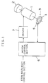
- Fig. 1 is a block diagram showing the construction of a motor driving and control device according to one embodiment of the present invention.
- a motor 1 is, for example, a DC servo motor and is for driving a load 2.
- a conveying belt of an automatic document feeder mounted on, for example, a copying machine is considered as the load 2.
- an optical system for illuminating and scanning a document in the copying machine is considered as the load 2.
- an arbitrary driving member is considered as the load 2.
- a detector 3 for detecting the rotating state of the motor 1 is connected to an axis of rotation of the motor 1.
- the detector 3 is a single-phase type encoder which is constituted by a rotating disc 4 having a lot of slits radially, for example, formed therein and a photointerruptor 5 optically connected to the rotating disc 4.
- Such construction makes it possible to construct the detector 3 simply and at low cost.
- a total of 70 to 80 slits, for example, are radially formed in the rotating disc 4. Therefore, if the motor 1 is rotated once, 70 to 80 pulses are output from the photointerruptor 5.
- the detector 3 constructed as described above may be replaced with another equipment for outputting pulses which are periodically synchronized with the rotation of the servo motor 1, for example, a frequency generator.
- Output pulses of the photointerruptor 5 are applied to the motor control section 6.
- the motor control section 6 is provided with a microcomputer and a memory.
- the motor 1 is so controlled as to be rotated in the reverse direction and the time when the motor 1 is actually rotated in the reverse direction is detected by the motor control section 6.
- a control signal of the motor control section 6 is applied to a driver 7.
- the motor 1 is rotated by the driver 7.
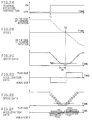
- Fig. 2 is a waveform diagram showing the relationship among a reverse rotation instruction signal output from the motor control section 6, the actual rotation speed of the motor 1, and speed data and acceleration data detected by the motor control section 6 on the basis of the pulses output from the photointerruptor 5.
- the reverse rotation instruction signal is turned on, the actual speed of the motor 1 is gradually reduced from constant-speed rotation on the side of the forward rotation at that timing and finally, becomes zero at time t2. Thereafter, the motor 1 is rotated in the reverse direction from the time t2.
- the actual speed of the motor 1 is grasped imaginarily as stepped-shaped speed data as shown in Fig. 2C in the motor control section 6 on the basis of the detection pulses of the photointerruptor 5.
- the acceleration of the motor 1 is grasped as shown in Fig. 2D imaginarily in the motor control section 6 on the basis of the detection pulses of the photointerruptor 5.
- a circuit for calculating pulse width data CWDT of the photointerruptor 5 as shown in Fig. 3 is provided so as to calculate the data shown in Figs. 2C and 2D in the motor control section 6.
- the pulses output from the photointerruptor 5 are applied to an edge detecting circuit 61.
- the edge detecting circuit 61 detects the leading edge, for example, of the applied pulses and derives its detection output.
- the detection output is applied to an up counter 62, to be counted.
- a free-running counter 63 of, for example, 16-bit construction for counting reference clocks up is provided in the circuit for calculating pulse width data CWDT.
- the free-running counter 63 counts machine clocks of the microcomputer having a frequency of, for example, approximately 1,5 MHz as reference clocks.
- an output of the edge detecting circuit 61 is applied to a capture register 64 as a capture signal.
- the capture register 64 uses the capture signal applied from the edge detecting circuit 61 as a trigger to read and hold the counted number of the free-running counter 63. Consequently, the contents of the capture register 64 are gradually updated by the output of the edge detecting circuit 61, that is, the leading edge of the pulses outputted from the photointerruptor 5.
- pulse width data CWDT applied from the photointerruptor 5 is calculated by the following equation: Accordingly, the rotation speed N of the motor 1 is as follows: where C : the number of pulses output from the photointerruptor 5 when the motor 1 is rotated once.
- the up counter 62 may be replaced with an up-down counter which is switched to the countdown if the reverse rotation of the motor 1 is detected.
- the absolute value of the denominator in the right side is found in consideration of a case where the up-down counter is used.
- the average acceleration for the very small unit time period ⁇ t is found by the following equation: where N' : the calculated speed for the preceding very small unit time period.
- the motor 1 is rotated in the reverse direction when the speed data shown in Fig. 2C is not more than a predetermined reference speed, or it is judged that the motor 1 is rotated in the reverse direction when a predetermined very small time period ⁇ t0 has elapsed since the speed data was not more than the reference speed so as to determine the more exact time when the motor 1 is rotated in the reverse direction.
- the motor 1 is rotated in the reverse direction at the time point where the speed data shown in Fig. 2C is not more than a predetermined reference speed Nth and the acceleration data shown in Fig. 2D is switched from the negative to the positive in this case.
- the following are devised to calculate the acceleration data.
- the speed data actually detected by the motor control section 6 hardly become stepped-shaped speed data as shown in Fig. 2C.
- the speed data becomes speed data which varies in calculated speed for each very small unit time period ⁇ t, as shown in Fig. 2E.
- the calculated acceleration data is not data which is clearly switched from the negative to the positive at a certain time point, as shown in Fig. 2D.
- the acceleration data becomes varying data which is switched between the negative and the positive for each very small unit time period ⁇ t, as shown in Fig. 2F.
- the acceleration data as shown in Fig. 2F is made use of by finding the average value of accelerations.
- the time point where the average value of the accelerations is switched from the negative to the positive is stored, and it is judged that the motor is rotated in the reverse direction at the above described stored time point where the average value of the accelerations is switched from the negative to the positive when the average value of the accelerations continues to be positive a predetermined number of times.
- the motor 1 shall be a motor for driving a conveying belt of an automatic document feeder mounted on, for example, a copying machine, and the motor control section 6 shall be a control section of the motor.
- a reverse rotation instruction is given to the motor control section 6 from a main body control section carrying out the entire control of the automatic document feeder.
- the motor control section 6 outputs the reverse rotation instruction to the driver 7.
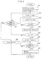
- an abnormality detecting timer 3 is started (step S1).
- a timer 1 is then started (step S2).
- the timer 1 is for measuring a very small unit time period ⁇ t.
- Pulses input from the photointerruptor 5 are then counted (step S3).
- the counting of the pulses is continued until the very small unit time period ⁇ t has elapsed (steps S4 ⁇ S3 ⁇ S4).
- the number of pulses is counted by the up counter 62, and the number of reference clocks during the counting is counted by the capture register 64, as described with reference to Fig. 3.
- pulse width data CWDT is found on the basis of the number of pulses (UDCn - UDCm) counted by the up counter 62 for the very small unit time period ⁇ t and the change (CPTn - CPTm) in the counted number of the capture register 64 for the very small unit time period ⁇ t, and the rotation speed N of the motor 1 is found on the basis of the equation (2) (step S5).
- step S6 It is judged whether or not the calculated rotation speed N is not more than the reference speed Nth (step S6).
- step S7 Unless the calculated rotation speed N is not more than the reference speed Nth as the result of the judgment, it is judged whether or not the timer 3 reaches the full count (step S7).
- the timer 3 is an abnormality detecting timer as described above. As the time period measured by the timer 3, a sufficient time period required to detect the reverse rotation is previously set by the timer 3. Therefore, the timer 3 does not reach the full count at this time point so long as it is normally operated. Consequently, the control in the step S2 and the subsequent steps is repeated, so that a speed N for the succeeding very small unit time period ⁇ t is calculated (steps S2 to S5).
- step S7 when it is judged in the step S7 that the timer 3 reaches the full count, that is, unless the speed N of the motor 1 is not more than the predetermined reference speed Nth even if a sufficient time period required to detect the reverse rotation of the motor 1 which is set by the timer 3 has elapsed, it is judged that an abnormality occurs, so that the motor 1 is stopped (step S8). Consequently, this control is terminated.
- the driving of the motor 1 may be stopped after the motor 1 continues to be rotated for a predetermined time period at a predetermined speed, for example, instead of immediately stopping the motor 1.
- the present embodiment is characterized in that the protection processing of the motor 1 is performed on the basis of the fact that the timer 3 reaches the full count.
- step S10 If it is judged that the timer 2 reaches the full count by measuring the predetermined very small time period ⁇ t0 after the timer 2 is started (step S10), it is judged that the motor 1 is rotated in the reverse direction at the time point (step S11).
- the timer 2 is started after the rotation speed N of the motor 1 is not more than the reference speed Nth, it is possible to consider that the motor 1 is rotated in the reverse direction at the time point where it is judged that the rotation speed N of the motor 1 is not more than the reference speed Nth in the step S6 by setting a threshold value for judging whether or not the speed of the motor 1 is not more than a predetermined speed (a reference speed Nth) to a sufficiently low value.
- Fig. 6 is a flow chart for explaining another control operation of the motor control section 6.
- an example is shown in which acceleration data is made use of for the motor control section 6 to detect the time point where the motor 1 is rotated in the reverse direction.
- step S21 If a reverse rotation instruction is given to the motor control section 6 from a main body control section carrying out the entire control of the automatic document feeder, the motor control section 6 outputs the reverse rotation instruction to the driver 7, and an abnormality detecting timer 3 is started (step S21).
- a timer 1 is then started (step S22).
- the timer 1 is for measuring a very small unit time period ⁇ t.
- Pulses inputted from the photointerruptor 5 are then counted (step S23). The counting of the pulses is continued until the very small unit time period ⁇ t has elapsed.
- the number of pulses is counted by the up counter 62, and the number of reference clocks during the counting is counted by the capture register 64, as described with reference to Fig. 3.
- pulse width data CWDT is found on the basis of the number of pulses (UDCn - UDCm) counted by the up counter 62 for the very small unit time period ⁇ t and the change (CPTn - CPTm) in the counted number of the capture register 64 for the very small unit time period ⁇ t, and the rotation speed N of the motor 1 is found on the basis of the equation (2) (step S25).
- step S26 an acceleration ⁇ for the very small unit time period ⁇ t is calculated (step S26).
- the acceleration ⁇ is found by the foregoing equation (3).
- the timer 3 is an abnormality detecting timer, as described above, and is for measuring a sufficient time period required to detect the reverse rotation of the motor 1. Therefore, the timer 3 does not reach the full count at this time point in the normal state. Consequently, the control in the step S22 and the subsequent steps is repeated, so that a speed N for the subsequent very small unit time period ⁇ t is calculated, and an acceleration ⁇ for the very small time period is found (steps S22 to S26).
- step S28 If it is judged in the step S28 that the timer 3 reaches the full count, that is, unless the speed N of the motor 1 is not more than the reference speed Nth within a sufficient time period required to detect the reverse rotation of the motor 1, it is judged that an abnormality occurs, so that the motor 1 is stopped (step S29).
- the motor 1 is so controlled as to be immediately stopped as a protecting operation on the basis of the fact that the timer 3 reaches the full count.
- the motor 1 may be stopped after being driven for a predetermined time period at a predetermined low speed instead of immediately stopping the motor 1.
- step S27 it is judged in the step S27 that the calculated rotation speed N is not more than the reference speed Nth by the time when the timer 3 reaches the full count. Consequently, it is judged whether or not the acceleration ⁇ becomes positive (step S30).
- the acceleration ⁇ is negative while the motor 1 is being decelerated, while being switched to the positive if the motor 1 starts to be accelerated, as shown in Fig. 2D. Consequently, if the acceleration ⁇ is not positive, that is, if the acceleration ⁇ is negative, the motor 1 is not rotated in the reverse direction, that is, the motor 1 is being decelerated.
- step S31 When the acceleration ⁇ is not positive, it is then judged whether or not the timer 3 reaches the full count (step S31). Unless the acceleration ⁇ becomes positive by the time when the timer 3 reaches the full count, which means that the reverse rotation of the motor 1 is not detected within a sufficient time period required to detect the reverse rotation, it is judged that an abnormality occurs, so that the motor 1 is stopped (step S29).
- step S31 it is judged in the step S31 that the timer 3 does not reach the full count, so that the reverse rotation of the motor 1 is detected (step S32) at the time point where the acceleration ⁇ becomes positive in the step S30.
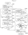
- Fig. 7 is a flow chart showing the contents of control for detecting the reverse rotation of a motor according to still another embodiment of the present invention.
- a reverse rotation instruction is given to the motor control section 6 from a main body control section carrying out the entire control of the automatic document feeder.
- the motor control section 6 outputs the reverse rotation instruction to the driver 7 (step S41).
- a timer 1 is started (step S42).
- the timer 1 is for measuring a very small unit time period ⁇ t.
- Pulses input from the photointerruptor 5 are then counted (step S43).
- the counting of the pulses is continued until the very small unit time period ⁇ t has elapsed (step S44 ⁇ S43 ⁇ S44).
- the number of pulses is counted by the up counter 62, and the number of reference clocks during the counting is counted by the capture register 64, as described with reference to Fig. 3.
- pulse width data CWDT is found on the basis of the number of pulses (UDCn - UDCm) counted by the up counter 62 for the very small unit time period ⁇ t and the change (CPTn - CPTm) in the counted number of the capture register 64 for the very small unit time period ⁇ t, and the rotation speed N of the motor 1 is found on the basis of the equation (2) (step S45).
- step S46 an acceleration ⁇ for the very small unit time period ⁇ t is calculated (step S46).
- the acceleration ⁇ is found by the foregoing equation (3).
- step S47 It is judged in the subsequent step S47 whether or not the rotation speed N calculated in the step S45 is not more than a reference speed Nth. Unless the calculated rotation speed N is not more than the reference speed Nth as the result of the judgment, the control in the step S42 and the subsequent steps is repeated, so that a speed N for the subsequent very small unit time period ⁇ t is calculated, and an acceleration ⁇ for the very small unit time period is found (steps S42 to S46).
- the average value of accelerations ⁇ is then calculated (step S48).
- the average value of accelerations ⁇ the average value of accelerations for a predetermined number of very small unit time periods ⁇ t including the newest acceleration is calculated. For example, the average value of accelerations for three very small unit time periods including the newest acceleration ⁇ is calculated.
- step S49 It is then judged whether or not the calculated average value of the accelerations is positive (step S49).
- the average value of the accelerations is negative while the motor 1 is being decelerated, while being switched to the positive if the motor 1 starts to be accelerated, as shown in Fig. 2F. Consequently, unless the average value of the accelerations is positive, the motor is being decelerated.
- step S50 If it is judged in the step S49 that the average value of the accelerations is positive, the time point where the judgment is made is then stored (step S50). Thereafter, it is judged whether or not the average value of the accelerations continues to be positive a predetermined number of times, for example, two times (step S51). If the average value of the accelerations continues to be positive, for example, two times, it is judged that the time point stored in the step S50 is the time point where the motor 1 is rotated in the reverse direction (step S52).
- the abnormality detecting timer 3 may be provided as in the control shown in Fig. 5 or 6 so that it is judged that an abnormality occurs by the fact that the timer 3 reaches the full count before the reverse rotation of the motor 1 is detected, to stop the motor 1. Consequently, in a case where the time point where the motor is actually rotated in the reverse direction is detected by a single-phase type encoder only outputting pulses in synchronism with the rotation of the motor, even if there occurs the situation where the reverse rotation of the motor is not detected, a reverse rotation voltage can be prevented from being continuously applied to the motor.
Landscapes
- Engineering & Computer Science (AREA)
- Power Engineering (AREA)
- Control Of Electric Motors In General (AREA)
Applications Claiming Priority (4)
| Application Number | Priority Date | Filing Date | Title |
|---|---|---|---|
| JP4158291A JP2723757B2 (ja) | 1992-06-17 | 1992-06-17 | モータ制御装置 |
| JP158292/92 | 1992-06-17 | ||
| JP158291/92 | 1992-06-17 | ||
| JP4158292A JP2769067B2 (ja) | 1992-06-17 | 1992-06-17 | モータ制御装置 |
Publications (1)
| Publication Number | Publication Date |
|---|---|
| EP0574931A1 true EP0574931A1 (de) | 1993-12-22 |
Family
ID=26485461
Family Applications (1)
| Application Number | Title | Priority Date | Filing Date |
|---|---|---|---|
| EP93109726A Withdrawn EP0574931A1 (de) | 1992-06-17 | 1993-06-17 | Vorrichtung zur Steuerung eines Motors in Gegenrichtung und Verfahren zur Bestimmung des Zeitpunkts bei dem der Motor wirklich in die Gegenrichtung gedreht wird |
Country Status (1)
| Country | Link |
|---|---|
| EP (1) | EP0574931A1 (de) |
Cited By (3)
| Publication number | Priority date | Publication date | Assignee | Title |
|---|---|---|---|---|
| FR2881004A1 (fr) * | 2005-01-14 | 2006-07-21 | Arvinmeritor Light Vehicle Sys | Procede de determination du changement du sens de rotation d'un moteur |
| CN103134948A (zh) * | 2011-11-21 | 2013-06-05 | Abb公司 | 用于检测离心机的正确旋转方向的方法及离心机组件 |
| CN115360941A (zh) * | 2022-08-08 | 2022-11-18 | 广州汽车集团股份有限公司 | 一种电机回转位置识别方法、ecu及汽车 |
Citations (1)
| Publication number | Priority date | Publication date | Assignee | Title |
|---|---|---|---|---|
| EP0327109A1 (de) * | 1988-02-05 | 1989-08-09 | Sharp Kabushiki Kaisha | Vorrichtung zum Anhalten eines Motors |
-
1993
- 1993-06-17 EP EP93109726A patent/EP0574931A1/de not_active Withdrawn
Patent Citations (1)
| Publication number | Priority date | Publication date | Assignee | Title |
|---|---|---|---|---|
| EP0327109A1 (de) * | 1988-02-05 | 1989-08-09 | Sharp Kabushiki Kaisha | Vorrichtung zum Anhalten eines Motors |
Non-Patent Citations (1)
| Title |
|---|
| PATENT ABSTRACTS OF JAPAN vol. 9, no. 27 (E-294)6 February 1985 & JP-A-59 172 993 ( HITACHI SEISAKUSHO KK ) 29 September 1984 * |
Cited By (4)
| Publication number | Priority date | Publication date | Assignee | Title |
|---|---|---|---|---|
| FR2881004A1 (fr) * | 2005-01-14 | 2006-07-21 | Arvinmeritor Light Vehicle Sys | Procede de determination du changement du sens de rotation d'un moteur |
| US7283887B2 (en) | 2005-01-14 | 2007-10-16 | Arvinmeritor Light Vehicle Systems - France | Method for determining a change in direction of rotation of a motor |
| CN103134948A (zh) * | 2011-11-21 | 2013-06-05 | Abb公司 | 用于检测离心机的正确旋转方向的方法及离心机组件 |
| CN115360941A (zh) * | 2022-08-08 | 2022-11-18 | 广州汽车集团股份有限公司 | 一种电机回转位置识别方法、ecu及汽车 |
Similar Documents
| Publication | Publication Date | Title |
|---|---|---|
| US5650779A (en) | Position encoder | |
| EP0935335A1 (de) | Positionsregler | |
| EP0735664A2 (de) | Mit hoher Taktfrequenz arbeitendes Winkelregelungssystem für einen geschalteten Reluktanzmotorantrieb | |
| CA1175892A (en) | Apparatus for stepper motor position control | |
| US5442267A (en) | Device for controlling the reverse rotation of a motor and method of judging time point where the motor is actually rotated in a reverse direction | |
| US5077507A (en) | Servo control apparatus | |
| EP0574931A1 (de) | Vorrichtung zur Steuerung eines Motors in Gegenrichtung und Verfahren zur Bestimmung des Zeitpunkts bei dem der Motor wirklich in die Gegenrichtung gedreht wird | |
| EP0409185B1 (de) | Verfahren zur Berechnung der Regelspannung und Motorregelvorrichtung, die dieses Verfahren anwendet | |
| EP0374797A1 (de) | Digitales Servosystem zur Regelung der Drehgeschwindigkeit eines rotierenden Körpers | |
| US5130626A (en) | Device for controlling rotational speed of motor | |
| US5941359A (en) | Positioning apparatus | |
| EP0488350A2 (de) | Verfahren und Einrichtung zum Steuern eines Motors | |
| JP2723757B2 (ja) | モータ制御装置 | |
| EP1227572A2 (de) | Steuervorrichtung für einen Gleichstrommotor | |
| JP2769067B2 (ja) | モータ制御装置 | |
| JPS6359796A (ja) | パルスモ−タの原点復帰方式 | |
| JP2740953B2 (ja) | 主軸定位置停止制御装置 | |
| JP3173848B2 (ja) | モーターの駆動制御装置 | |
| US4612657A (en) | Device for detecting momentary cutoff of AC power source | |
| KR100215763B1 (ko) | 저속주행시의테이프위치감지방법 | |
| JPH066995A (ja) | モータ制御装置 | |
| JP2957216B2 (ja) | モータ制御装置 | |
| JP2735324B2 (ja) | モータの回転速度制御装置 | |
| JPH0839298A (ja) | プレス機械のスライド停止時間測定装置 | |
| KR930000183B1 (ko) | 시리얼 프린터 |
Legal Events
| Date | Code | Title | Description |
|---|---|---|---|
| PUAI | Public reference made under article 153(3) epc to a published international application that has entered the european phase |
Free format text: ORIGINAL CODE: 0009012 |
|
| AK | Designated contracting states |
Kind code of ref document: A1 Designated state(s): DE FR GB IT |
|
| 17P | Request for examination filed |
Effective date: 19931109 |
|
| 17Q | First examination report despatched |
Effective date: 19950825 |
|
| STAA | Information on the status of an ep patent application or granted ep patent |
Free format text: STATUS: THE APPLICATION IS DEEMED TO BE WITHDRAWN |
|
| 18D | Application deemed to be withdrawn |
Effective date: 19960305 |