EP0574968A1 - Verfahren zur Beeinflussung des Fahrverhaltens eines Fahrzeuges mit einem stufenlosen Getriebe - Google Patents
Verfahren zur Beeinflussung des Fahrverhaltens eines Fahrzeuges mit einem stufenlosen Getriebe Download PDFInfo
- Publication number
- EP0574968A1 EP0574968A1 EP93201320A EP93201320A EP0574968A1 EP 0574968 A1 EP0574968 A1 EP 0574968A1 EP 93201320 A EP93201320 A EP 93201320A EP 93201320 A EP93201320 A EP 93201320A EP 0574968 A1 EP0574968 A1 EP 0574968A1
- Authority
- EP
- European Patent Office
- Prior art keywords
- rate
- revolution
- accelerator pedal
- values
- axle
- Prior art date
- Legal status (The legal status is an assumption and is not a legal conclusion. Google has not performed a legal analysis and makes no representation as to the accuracy of the status listed.)
- Granted
Links
Images
Classifications
-
- F—MECHANICAL ENGINEERING; LIGHTING; HEATING; WEAPONS; BLASTING
- F16—ENGINEERING ELEMENTS AND UNITS; GENERAL MEASURES FOR PRODUCING AND MAINTAINING EFFECTIVE FUNCTIONING OF MACHINES OR INSTALLATIONS; THERMAL INSULATION IN GENERAL
- F16H—GEARING
- F16H61/00—Control functions within control units of change-speed- or reversing-gearings for conveying rotary motion ; Control of exclusively fluid gearing, friction gearing, gearings with endless flexible members or other particular types of gearing
- F16H61/66—Control functions within control units of change-speed- or reversing-gearings for conveying rotary motion ; Control of exclusively fluid gearing, friction gearing, gearings with endless flexible members or other particular types of gearing specially adapted for continuously variable gearings
- F16H61/662—Control functions within control units of change-speed- or reversing-gearings for conveying rotary motion ; Control of exclusively fluid gearing, friction gearing, gearings with endless flexible members or other particular types of gearing specially adapted for continuously variable gearings with endless flexible members
- F16H61/66254—Control functions within control units of change-speed- or reversing-gearings for conveying rotary motion ; Control of exclusively fluid gearing, friction gearing, gearings with endless flexible members or other particular types of gearing specially adapted for continuously variable gearings with endless flexible members controlling of shifting being influenced by a signal derived from the engine and the main coupling
Definitions
- the invention pertains to a method for influencing the transmission ratio in a continuously variable transmission, whereby the choice of a desired value N p (DV) of the rate of revolution of the primary axle (2) of the system occurs on the basis of the current positional values ( ⁇ ) of an accelerator pedal and a current rate of revolution value N s of the secondary axle (8) of the system.
- the invention pertains to a continuously variable transmission system, provided with a transmission with a primary pulley and a secondary pulley, whereby each pulley includes two discs, between which discs a driving belt is fitted, which belt's working radii can be varied by means of control means fitted to an adjustable portion of one or both pulleys, and provided with selection means with an input for the application of an accelerator pedal signal ( ⁇ ) and an input for the application of a signal N s , which signal is a measure of the value of the rate of revolution N s of the secondary axle, and an output N p (DV) for the selected desired value of the rate of revolution N p (DV) of the secondary axle, which output is connected to said selection means.
- ⁇ accelerator pedal signal
- N s which signal is a measure of the value of the rate of revolution N s of the secondary axle
- N p (DV) for the selected desired value of the rate of revolution N p (DV) of the secondary axle
- a particular selection circuit is known from the above, wherein the accelerator pedal signal ( ⁇ ), together with a signal N s , which signal is a measure of the current value of the rate of revolution of the secondary axle, is used to select a desired value N p (DV) of the rate of revolution of the primary axle, with which selection circuit control means coupled to the adjustable portion of the primary pulley are driven, in order to thereby influence the transmission ratio.
- the goal of the invention in question is to increase the degree of acceptability of the continuously variable transmission to the public at large, and to further improve the comfort and control thereof, and to endow it with a greater flexibility and applicability by creating the possibility of equipping the system to allow it to meet the individual requirements of any driver
- the method according to the invention is characterised in that one or more sub ranges from the range of possible desired rate of revolution values N p of the primary axle are composed, and that the possible positional values ( ⁇ ) of the accelerator pedal can be combined with one of the said sub ranges, to choice.
- each sub range is is composed in such a way that the content serves as a model for a desired driving programme.
- the boundary values of the sub range are continuously adjustable, whereby at any moment a target driving performance can be optimally matched to the individual needs of the driver.
- Characteristic of the continuously variable transmission system according to the invention is that the selection means are arranged in such a way that one or more sub ranges are composed from a range of possible desired rate of revolution values N p of the primary axle, which sub ranges are stored in a memory of the selection means, whereby boundary values of a sub range correspond to accelerator pedal positions of 0% and 100%, respectively.
- the invention shall be, together with its further advantages, elucidated on the basis of the attached drawings.
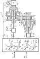
- the figure thereby depicts a schematic rendition of a continuously variable transmission system in accordance with the invention, which figure will also be used to elucidate the method according to the invention.
- the figure shows a continuously variable transmission 1, containing a primary axle 2, upon which primary axle a primary pulley in the form of primary conical pulley discs 3 and 4 is fitted.
- the pulley disc 3 hereof is fixed rigidly to the primary axle 2 and the primary pulley disc 4 is movable over the axle 2 by means of the exertion of a hydraulic pressure in a primary pressure chamber 5.
- the control of the pressure in the primary pressure chamber 5 occurs through the use of primary control means 6 connected to the pressure chamber 5.
- the working radii of a driving belt 7 fitted between pulley discs 3 and 4 can be thereby adjusted.
- the transmission 1 contains a secondary axle 8, to which axle a pulley with secondary conical pulley discs 9 and 10 is fitted.
- Pulley disc 9 is fixed rigidly to the axle 8 and pulley disc 10 is fitted to the axle 8 in such a way that it can be slid.
- the pulley disc 10, which can be axially slid on the axle 8, is displaced by the exertion of a hydraulic pressure in a secondary pressure chamber 11, which pressure chamber is connected to secondary control means 12, to which secondary control means signals outside the scope of this description are supplied.
- the primary and secondary control means 6 and 12, respectively, are connected to the pressure chambers 5 and 11, respectively, by means of pipes 13 and 14, respectively. Moreover, the driving belt 7 is laid between the secondary pulley discs 9 and 10. The tension in the driving belt 7 is maintained through the exertion of a hydraulic pressure in a secondary pressure chamber 11 by the secondary control means 12.
- the continuously variable transmission system contains an engine 15 coupled to the primary axle 2, which engine is controlled with the aid of a fuel supply device 16.
- the device 16 contains a steering input 17 to which a fuel supply rate control signal ⁇ provided by selection means 18 is delivered.
- the selection means 18 contain an input 19, to which by non-depicted means an input signal ⁇ , which signal contains a measure of the position of the accelerator pedal in a vehicle, is delivered.
- the signal ⁇ at control input 17, which signal is based on signal ⁇ , is generated in the control device 18.
- an adjustable relationship exists between the signals ⁇ and ⁇ , whereby the flexibility and the variability of the continuously variable transmission system are increased and a wide application range for a large group of users is created.
- E, C, S, and V Four driving characteristics indicated by E, C, S, and V, respectively, are included within the scope of the selection means 18, within which driving characteristics the rate of revolution N s of the secondary axle 8 is reproduced, which rate of revolution is a measure for the speed of the vehicle as a function of the rate of revolution N p of the primary axle 2 , which rate is representative of the rate of revolution of the engine 15.
- the symbols represent, successively, economic, comfortable, sporty and variably-selectable driving programmes.
- the transmission ratio i hereby, is defined as the quotient of the rate of revolution N p of the primary axle and the rate of revolution N s of the secondary axle.
- the symbols A and B which stand for the lower and upper limits of Np, respectively, are placed beside vertical lines in the various characteristics, which vertical lines indicate the boundaries of subsets of the desired choices for the rate of revolution Np of the primary axle.
- the limits A and B are variable and the placement thereof can be influenced by means of one or more non-depicted potentiometers, the positions of which potentiometers can be adjusted by the driver of the vehicle to choice.
- the functioning of the system is such that after choosing a certain driving characteristic on the basis of signals ⁇ and N s , a certain value of N p (DV) is selected, which value is compared in control means 6 with a current, measured value N p (MV) of the rate of revolution of the primary axle 2.
- the pressure P prim is influenced on the basis of the difference between N p (DV) and N p (MV), whereby the current rate of revolution of the primary axle 2 changes.
- the engine 15 Given a certain value of the accelerator pedal signal ⁇ and of the signal ⁇ , the engine 15 shall start to operate at the modified current value of the primary axle 2 and shall deliver a torque to the axle 2, which torque is in harmony with the position of the fuel supply device 16, which position is determined by the value of the signal b.
- the choice between the different driving characteristics and/or the adjustable limits A and B can be made, if desired, with the assistance of fuzzy logic. Every desired relation of N p can be placed between the limits A and B.
- the relation may be, but does not necessarily have to be, linear.
Landscapes
- Engineering & Computer Science (AREA)
- General Engineering & Computer Science (AREA)
- Mechanical Engineering (AREA)
- Control Of Transmission Device (AREA)
- Arrangement And Mounting Of Devices That Control Transmission Of Motive Force (AREA)
Applications Claiming Priority (2)
| Application Number | Priority Date | Filing Date | Title |
|---|---|---|---|
| NL9201051A NL9201051A (nl) | 1992-06-15 | 1992-06-15 | Werkwijze voor het beinvloeden van het rijgedrag van een voertuig met een continu variabele transmissie. |
| NL9201051 | 1992-06-15 |
Publications (2)
| Publication Number | Publication Date |
|---|---|
| EP0574968A1 true EP0574968A1 (de) | 1993-12-22 |
| EP0574968B1 EP0574968B1 (de) | 1996-09-18 |
Family
ID=19860924
Family Applications (1)
| Application Number | Title | Priority Date | Filing Date |
|---|---|---|---|
| EP93201320A Expired - Lifetime EP0574968B1 (de) | 1992-06-15 | 1993-05-07 | Verfahren zur Beeinflussung des Fahrverhaltens eines Fahrzeuges mit einem stufenlosen Getriebe |
Country Status (6)
| Country | Link |
|---|---|
| US (1) | US5545105A (de) |
| EP (1) | EP0574968B1 (de) |
| JP (1) | JP3863575B2 (de) |
| DE (1) | DE69304808T2 (de) |
| ES (1) | ES2094462T3 (de) |
| NL (1) | NL9201051A (de) |
Cited By (4)
| Publication number | Priority date | Publication date | Assignee | Title |
|---|---|---|---|---|
| WO1994024463A1 (de) * | 1993-04-20 | 1994-10-27 | Zf Friedrichshafen Ag | Schaltvorrichtung für ein stufenloses getriebe eines kraftfahrzeuges |
| DE4428684A1 (de) * | 1994-08-12 | 1996-02-15 | Bayerische Motoren Werke Ag | Stufenlos verstellbares Getriebe mit einer Steuereinheit zur Veränderung der Getriebeübersetzung |
| WO1997025557A1 (de) * | 1996-01-12 | 1997-07-17 | Zf Friedrichshafen Ag | Verfahren zur vorgabe der übersetzung eines stufenlosen getriebes |
| DE19821481A1 (de) * | 1998-05-14 | 1999-11-25 | Iav Gmbh | Verfahren und Einrichtung zur Steuerung einer Kraftfahrzeug-Antriebseinheit mit Verbrennungsmotor und CVT-Getriebe |
Families Citing this family (3)
| Publication number | Priority date | Publication date | Assignee | Title |
|---|---|---|---|---|
| DE19602032C2 (de) * | 1996-01-20 | 2000-06-15 | Telefunken Microelectron | Verfahren zur Regelung stufenloser Getriebe von Kraftfahrzeugen |
| DE19602033C2 (de) * | 1996-01-20 | 2000-06-21 | Telefunken Microelectron | Verfahren zur Regelung stufenlos verstellbarer Getriebe von Kraftfahrzeugen |
| DE102016200336A1 (de) * | 2016-01-14 | 2017-07-20 | Zf Friedrichshafen Ag | Verfahren zum Betreiben eines Fahrzeugantriebsstranges einer Arbeitsmaschine mit einer Antriebsmaschine, mit einem Getriebe und mit einem Abtrieb |
Citations (4)
| Publication number | Priority date | Publication date | Assignee | Title |
|---|---|---|---|---|
| DE3428098A1 (de) * | 1983-07-30 | 1985-02-14 | Mazda Motor Corp., Hiroshima | Riemengetriebe mit stufenloser uebersetzung |
| US4926716A (en) * | 1987-08-10 | 1990-05-22 | Suzuki Jidosha Kogyo Kabushiki Kaisha | Method of controlling continuously variable transmission system |
| US5056380A (en) * | 1988-08-30 | 1991-10-15 | Mazda Motor Corporation | Hydraulic control system for steplessly variable transmission |
| EP0451887B1 (de) * | 1990-04-12 | 1995-06-07 | Van Doorne's Transmissie B.V. | Stufenlos regelbares Getriebe mit elektronischer Steuerung |
Family Cites Families (9)
| Publication number | Priority date | Publication date | Assignee | Title |
|---|---|---|---|---|
| JPS61115735A (ja) * | 1984-11-12 | 1986-06-03 | Aisin Warner Ltd | 車両用動力伝達装置の制御装置 |
| US4793217A (en) * | 1985-09-17 | 1988-12-27 | Toyota Jidosha Kabushiki Kaisha | Method and apparatus for controlling power transmitting system for automotive vehicle, including continuously variable transmission and auxiliary transmission |
| JPS62137239A (ja) * | 1985-12-11 | 1987-06-20 | Toyota Motor Corp | 副変速機を備えた車両用無段変速機の制御方法 |
| JPS6299226A (ja) * | 1985-10-28 | 1987-05-08 | Fuji Heavy Ind Ltd | 無段変速機の制御方法 |
| JPH0674016B2 (ja) * | 1985-12-16 | 1994-09-21 | 富士重工業株式会社 | 無段変速機の制御装置 |
| JPS63242739A (ja) * | 1987-03-31 | 1988-10-07 | Toyota Motor Corp | 車両の駆動制御装置 |
| JPH03275436A (ja) * | 1990-03-15 | 1991-12-06 | Fumio Horibe | 液体容器 |
| DE4120540C1 (de) * | 1991-06-21 | 1992-11-05 | Dr.Ing.H.C. F. Porsche Ag, 7000 Stuttgart, De | |
| DE4120546C2 (de) * | 1991-06-21 | 1995-04-13 | Porsche Ag | Einrichtung zur Steuerung eines stufenlosen Kraftfahrzeuggetriebes |
-
1992
- 1992-06-15 NL NL9201051A patent/NL9201051A/nl not_active Application Discontinuation
-
1993
- 1993-05-07 ES ES93201320T patent/ES2094462T3/es not_active Expired - Lifetime
- 1993-05-07 DE DE69304808T patent/DE69304808T2/de not_active Expired - Lifetime
- 1993-05-07 EP EP93201320A patent/EP0574968B1/de not_active Expired - Lifetime
- 1993-06-11 JP JP16503093A patent/JP3863575B2/ja not_active Expired - Lifetime
- 1993-06-14 US US08/076,611 patent/US5545105A/en not_active Expired - Lifetime
Patent Citations (4)
| Publication number | Priority date | Publication date | Assignee | Title |
|---|---|---|---|---|
| DE3428098A1 (de) * | 1983-07-30 | 1985-02-14 | Mazda Motor Corp., Hiroshima | Riemengetriebe mit stufenloser uebersetzung |
| US4926716A (en) * | 1987-08-10 | 1990-05-22 | Suzuki Jidosha Kogyo Kabushiki Kaisha | Method of controlling continuously variable transmission system |
| US5056380A (en) * | 1988-08-30 | 1991-10-15 | Mazda Motor Corporation | Hydraulic control system for steplessly variable transmission |
| EP0451887B1 (de) * | 1990-04-12 | 1995-06-07 | Van Doorne's Transmissie B.V. | Stufenlos regelbares Getriebe mit elektronischer Steuerung |
Non-Patent Citations (4)
| Title |
|---|
| PATENT ABSTRACTS OF JAPAN vol. 010, no. 301 (M-525)14 October 1986 & JP-A-61 115 735 ( AISIN WARNER LTD. ) 3 June 1986 * |
| PATENT ABSTRACTS OF JAPAN vol. 011, no. 316 (M-631)15 October 1987 & JP-A-62 099 226 ( FUJI HEAVY IND. LTD. ) 8 May 1987 * |
| PATENT ABSTRACTS OF JAPAN vol. 011, no. 360 (M-645)25 November 1987 & JP-A-62 137 239 ( TOYOTA MOTOR CORP. ) 20 June 1987 * |
| PATENT ABSTRACTS OF JAPAN vol. 011, no. 364 (M-646)27 November 1987 & JP-A-62 139 731 ( FUJI HEAVY IND. LTD. ) 23 June 1987 * |
Cited By (8)
| Publication number | Priority date | Publication date | Assignee | Title |
|---|---|---|---|---|
| WO1994024463A1 (de) * | 1993-04-20 | 1994-10-27 | Zf Friedrichshafen Ag | Schaltvorrichtung für ein stufenloses getriebe eines kraftfahrzeuges |
| US5688204A (en) * | 1993-04-20 | 1997-11-18 | Zf Friedrichshafen Ag | Shifting device for a motor vehicle continuously variable transmission |
| DE4428684A1 (de) * | 1994-08-12 | 1996-02-15 | Bayerische Motoren Werke Ag | Stufenlos verstellbares Getriebe mit einer Steuereinheit zur Veränderung der Getriebeübersetzung |
| DE4428684C2 (de) * | 1994-08-12 | 1999-06-24 | Bayerische Motoren Werke Ag | Stufenlos verstellbares Getriebe in Kraftfahrzeugen mit einer Steuereinheit |
| WO1997025557A1 (de) * | 1996-01-12 | 1997-07-17 | Zf Friedrichshafen Ag | Verfahren zur vorgabe der übersetzung eines stufenlosen getriebes |
| US6173227B1 (en) | 1996-01-12 | 2001-01-09 | Zf Friedrichshafen Ag | Method of setting the transmission ratio of a continuously variable gear |
| DE19821481A1 (de) * | 1998-05-14 | 1999-11-25 | Iav Gmbh | Verfahren und Einrichtung zur Steuerung einer Kraftfahrzeug-Antriebseinheit mit Verbrennungsmotor und CVT-Getriebe |
| DE19821481C2 (de) * | 1998-05-14 | 2003-07-17 | Iav Gmbh | Verfahren und Einrichtung zur Steuerung einer Kraftfahrzeug-Antriebseinheit mit Verbrennungsmotor und CVT-Getriebe |
Also Published As
| Publication number | Publication date |
|---|---|
| DE69304808T2 (de) | 1997-05-07 |
| US5545105A (en) | 1996-08-13 |
| EP0574968B1 (de) | 1996-09-18 |
| JP3863575B2 (ja) | 2006-12-27 |
| DE69304808D1 (de) | 1996-10-24 |
| NL9201051A (nl) | 1994-01-03 |
| JPH0650421A (ja) | 1994-02-22 |
| ES2094462T3 (es) | 1997-01-16 |
Similar Documents
| Publication | Publication Date | Title |
|---|---|---|
| EP0217221B1 (de) | Verfahren und Vorrichtung zum Steuern einer Kraftübertragung für Fahrzeuge mit einem stufenlosen Getriebe und einem Zusatzgetriebe | |
| US5890991A (en) | Control system and method of continuously variable transmission | |
| US3726159A (en) | Transmission shift pattern generator | |
| US5688204A (en) | Shifting device for a motor vehicle continuously variable transmission | |
| CA2077096A1 (en) | Vehicle Automatic Transmission Control System | |
| US5129288A (en) | Transmission control system for automatic transmission | |
| US5545105A (en) | Method for influencing the driving behaviour of a vehicle with a continuously variable transmission | |
| US6173227B1 (en) | Method of setting the transmission ratio of a continuously variable gear | |
| AU701532B2 (en) | Kickdown control method for automatic transmission | |
| US5475591A (en) | Shift control system for automatic transmission based on fuzzy control | |
| US5871417A (en) | Continuously variable transmission control apparatus | |
| JPS63280955A (ja) | 無段変速機の変速比制御方法および変速比制御装置 | |
| JPH08501136A (ja) | 無段変速機の速度伝達比制御装置 | |
| DE102011056283A1 (de) | Steuerungsvorrichtung für ein stufenlos einstellbares Getriebe | |
| US5624348A (en) | Process for determining the shifting time for a transmission ratio change in an infinitely variable transmission | |
| US6350216B1 (en) | Method of ratio control for a CVT in a manual mode | |
| WO1998050248A1 (en) | A transmission control system for a vehicle | |
| US5642644A (en) | Control system and control process for an infinitely variable transmission | |
| JP3218962B2 (ja) | 無段変速機の変速制御装置 | |
| JP2006022913A (ja) | 無段変速機によるエンジンブレーキ制御装置 | |
| JPS62118146A (ja) | 自動変速機の変速制御装置 | |
| JP3510399B2 (ja) | 無段変速機の変速速度制御装置 | |
| JPH0517977B2 (de) | ||
| JP2583051B2 (ja) | 無段変速機の制御装置 | |
| JPS63662B2 (de) |
Legal Events
| Date | Code | Title | Description |
|---|---|---|---|
| PUAI | Public reference made under article 153(3) epc to a published international application that has entered the european phase |
Free format text: ORIGINAL CODE: 0009012 |
|
| 17P | Request for examination filed |
Effective date: 19930513 |
|
| AK | Designated contracting states |
Kind code of ref document: A1 Designated state(s): BE DE ES FR GB IT NL |
|
| 17Q | First examination report despatched |
Effective date: 19950220 |
|
| GRAG | Despatch of communication of intention to grant |
Free format text: ORIGINAL CODE: EPIDOS AGRA |
|
| GRAH | Despatch of communication of intention to grant a patent |
Free format text: ORIGINAL CODE: EPIDOS IGRA |
|
| GRAH | Despatch of communication of intention to grant a patent |
Free format text: ORIGINAL CODE: EPIDOS IGRA |
|
| GRAA | (expected) grant |
Free format text: ORIGINAL CODE: 0009210 |
|
| AK | Designated contracting states |
Kind code of ref document: B1 Designated state(s): BE DE ES FR GB IT NL |
|
| ITF | It: translation for a ep patent filed | ||
| REF | Corresponds to: |
Ref document number: 69304808 Country of ref document: DE Date of ref document: 19961024 |
|
| ET | Fr: translation filed |
Free format text: CORRECTIONS |
|
| REG | Reference to a national code |
Ref country code: ES Ref legal event code: FG2A Ref document number: 2094462 Country of ref document: ES Kind code of ref document: T3 |
|
| PLBE | No opposition filed within time limit |
Free format text: ORIGINAL CODE: 0009261 |
|
| STAA | Information on the status of an ep patent application or granted ep patent |
Free format text: STATUS: NO OPPOSITION FILED WITHIN TIME LIMIT |
|
| 26N | No opposition filed | ||
| REG | Reference to a national code |
Ref country code: GB Ref legal event code: IF02 |
|
| PGFP | Annual fee paid to national office [announced via postgrant information from national office to epo] |
Ref country code: ES Payment date: 20100520 Year of fee payment: 18 |
|
| PGFP | Annual fee paid to national office [announced via postgrant information from national office to epo] |
Ref country code: IT Payment date: 20100526 Year of fee payment: 18 |
|
| PGFP | Annual fee paid to national office [announced via postgrant information from national office to epo] |
Ref country code: BE Payment date: 20110525 Year of fee payment: 19 |
|
| PG25 | Lapsed in a contracting state [announced via postgrant information from national office to epo] |
Ref country code: IT Free format text: LAPSE BECAUSE OF NON-PAYMENT OF DUE FEES Effective date: 20110507 |
|
| PGFP | Annual fee paid to national office [announced via postgrant information from national office to epo] |
Ref country code: NL Payment date: 20120523 Year of fee payment: 20 |
|
| PGFP | Annual fee paid to national office [announced via postgrant information from national office to epo] |
Ref country code: GB Payment date: 20120522 Year of fee payment: 20 Ref country code: FR Payment date: 20120608 Year of fee payment: 20 |
|
| BERE | Be: lapsed |
Owner name: *VAN DOORNE'S TRANSMISSIE B.V. Effective date: 20120531 |
|
| REG | Reference to a national code |
Ref country code: ES Ref legal event code: FD2A Effective date: 20121207 |
|
| PGFP | Annual fee paid to national office [announced via postgrant information from national office to epo] |
Ref country code: DE Payment date: 20120725 Year of fee payment: 20 |
|
| PG25 | Lapsed in a contracting state [announced via postgrant information from national office to epo] |
Ref country code: ES Free format text: LAPSE BECAUSE OF NON-PAYMENT OF DUE FEES Effective date: 20110508 Ref country code: BE Free format text: LAPSE BECAUSE OF NON-PAYMENT OF DUE FEES Effective date: 20120531 |
|
| REG | Reference to a national code |
Ref country code: DE Ref legal event code: R071 Ref document number: 69304808 Country of ref document: DE |
|
| REG | Reference to a national code |
Ref country code: NL Ref legal event code: V4 Effective date: 20130507 |
|
| REG | Reference to a national code |
Ref country code: GB Ref legal event code: PE20 Expiry date: 20130506 |
|
| PG25 | Lapsed in a contracting state [announced via postgrant information from national office to epo] |
Ref country code: GB Free format text: LAPSE BECAUSE OF EXPIRATION OF PROTECTION Effective date: 20130506 Ref country code: DE Free format text: LAPSE BECAUSE OF EXPIRATION OF PROTECTION Effective date: 20130508 |