EP0575181A2 - Borne de batterie - Google Patents
Borne de batterie Download PDFInfo
- Publication number
- EP0575181A2 EP0575181A2 EP93304748A EP93304748A EP0575181A2 EP 0575181 A2 EP0575181 A2 EP 0575181A2 EP 93304748 A EP93304748 A EP 93304748A EP 93304748 A EP93304748 A EP 93304748A EP 0575181 A2 EP0575181 A2 EP 0575181A2
- Authority
- EP
- European Patent Office
- Prior art keywords
- tightening
- plate
- substrate
- bolt
- strip
- Prior art date
- Legal status (The legal status is an assumption and is not a legal conclusion. Google has not performed a legal analysis and makes no representation as to the accuracy of the status listed.)
- Granted
Links
Images


Classifications
-
- H—ELECTRICITY
- H01—ELECTRIC ELEMENTS
- H01R—ELECTRICALLY-CONDUCTIVE CONNECTIONS; STRUCTURAL ASSOCIATIONS OF A PLURALITY OF MUTUALLY-INSULATED ELECTRICAL CONNECTING ELEMENTS; COUPLING DEVICES; CURRENT COLLECTORS
- H01R11/00—Individual connecting elements providing two or more spaced connecting locations for conductive members which are, or may be, thereby interconnected, e.g. end pieces for wires or cables supported by the wire or cable and having means for facilitating electrical connection to some other wire, terminal, or conductive member, blocks of binding posts
- H01R11/11—End pieces or tapping pieces for wires, supported by the wire and for facilitating electrical connection to some other wire, terminal or conductive member
- H01R11/28—End pieces consisting of a ferrule or sleeve
- H01R11/281—End pieces consisting of a ferrule or sleeve for connections to batteries
- H01R11/282—End pieces consisting of a ferrule or sleeve for connections to batteries comprising means for facilitating engagement or disengagement, e.g. quick release terminal
Definitions
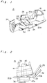
- the present invention relates to a battery terminal to be installed on an electrode (battery post) of a battery mounted on an automobile or the like and more particularly to the battery terminal which can be installed on the battery post downward and vertically.
- a battery post 2 projecting upward from the upper surface of a battery 1 is inserted into an electrode-engaging portion 3a of a battery terminal 3.
- a bolt 4 is horizontally inserted into a bolt opening of a substrate 3b and that of a tightening plate 3c.
- a nut 6 is tightened horizontally on the bolt 4 with an impact wrench 5 disposed horizontally. Then, the electrode-engaging portion 3a is pressed against the battery post 2 to fix the battery terminal 3 to the battery post 2.
- the following battery terminal is disclosed in Examined Japanese Utility Model Publication No. 4-7567 as shown in Fig. 11: That is, the bolt 4 is inclined at an acute angle with respect to the axis of the electrode-engaging portion 3a of the battery terminal 3, and the nut 6 is tightened diagonally downward toward the head of the bolt 4 by the impact wrench 5.
- the battery terminal comprises a substrate 3b'; a tightening plate 3c' opposed to each other and inversely tapered; and a crimping plate 7 inversely tapered and stretching over the substrate 3b' and the tightening plate 3c'.
- the bolt 4 is tightened downward on the crimping plate 7 so that the crimping plate 7 presses the substrate 3b' and the tightening plate 3c' downward. In this manner, an electrode-engaging portion 3a' is pressed against the battery post 2.
- the substrate 3b and the tightening plate 3c are formed by imparting torsion thereto so that they incline with respect to the axial direction of the electrode-engaging portion 3a.
- the direction in which the twisted substrate 3b and the tightening plate 3c are moved toward each other is different from the direction in which the electrode-engaging portion 3a is pressed against the peripheral surface of the battery post 2. Therefore, the force generated by the nut 6 tightened on the bolt 4 cannot be preferably applied to the direction in which the electrode-engaging portion 3a is pressed against the peripheral surface of the battery post 2.
- both sides of the crimping plate 7 are inversely tapered.
- the force generated by the nut 6 tightened on the bolt 4 acts outward as well as inward and thus, the sides 7a and 7b of the crimping plate 7 do not preferably apply tightening force inward to the substrate 3b' and the tightening plate 3c'.
- the electrode-engaging portion 3a' cannot be reliably pressed against the battery post 2.
- a battery terminal comprising first and second tightening plates continuous with an open free end of an annular electrode-engaging portion into which a battery post is inserted; and an electric wire-connecting portion continuous with the first tightening plate or the second tightening plate or the electrode-engaging portion, in which the first tightening plate is moved toward the second tightening plate to close the free end of the electrode-engaging portion so that the battery terminal is fixed to the battery post.
- a tightening strip disposed above the second tightening plate is formed on the first tightening plate integrally or continuously therewith; an elongated groove is formed on the tightening strip in the direction in which the first tightening plate is moved toward the second tightening plate; a sliding contact portion is formed at an end of the tightening strip in the longitudinal direction of the elongated groove; a tightening substrate is formed integrally with the second tightening plate; a bolt is installed upward on the tightening substrate through the elongated groove; and an inclined portion along which the sliding contact portion slides is formed integrally with the tightening substrate.
- the first and second tightening plates extend horizontally from the free end of the electrode-engaging portion; the first tightening plate inclines upward from the free end; and the tightening strip disposed above the second tightening plate is formed integrally with an end of the first tightening plate via a stepped portion.
- the first and second tightening plates each consisting of a flat plate vertically extending are opposed to each other; the tightening substrate extends beyond the lower end of the first tightening plate; the inclined portion opposed to the first tightening plate is formed at the end of the tightening substrate; the tightening strip separate from the first and second tightening plate is disposed above the tightening substrate with an end of the tightening plate in contact with the first tightening plate and the other end thereof in contact with the inclined portion; and the nut is tightened on the bolt projecting upward through the tightening substrate and the elongated groove formed on the tightening strip.
- the bolt is installed on the tightening substrate (second tightening plate) by inserting the bolt upward through a bolt opening formed on the tightening substrate (second tightening plate) so as to lock the head of the bolt by a locking strip projecting downward from the tightening substrate (second tightening plate) in tightening the nut on the bolt.
- a stud bolt may be inserted into the bolt opening and the flat head of the stud bolt in contact with the lower surface of the tightening substrate (second tightening plate) is welded onto the lower surface thereof.
- the free end of the electrode-engaging portion is open before the battery terminal is installed on the battery post. Therefore, the electrode-engaging portion can be easily installed on the battery post.
- the nut is tightened downward on the bolt vertically disposed.
- the sliding contact portion of the tightening strip moves downward along the inclined portion of the tightening substrate and the elongated groove of the tightening strip is moved along the bolt.
- the tightening strip moves downward and horizontally. That is, the tightening force, generated by the tightening of the nut on the bolt, acting downward is divided into the force acting in the direction in which the first tightening plate moves toward the second tightening plate and the force acting in the downward direction.
- the first tightening plate continuous with the tightening strip is moved to the second tightening plate. That is, the electrode-engaging portion of the battery terminal is moved in the closing direction thereof and thus can be pressed securely against the peripheral surface of the battery post and fixed thereto.
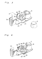
- a battery terminal 15 according to the first embodiment of the present invention will be described below with reference to Figs. 1 through 4. As shown in Fig. 1, a metal sheet is punched and bent to form the battery terminal 15 in an integral construction.
- the battery terminal 15 comprises an annular electrode-engaging portion 16 formed at the forward end thereof and a free end formed at the rear end thereof.
- the electrode-engaging portion 16 has a groove 18, formed vertically on the inner surface thereof, which contacts a battery terminal inserted thereinto so that the groove 18 allows the electrode-engaging portion 16 to be flexible. In this manner, the battery terminal 15 can be pressed against the battery post.
- Flat plates are projected from each free end of the electrode-engaging portion 16 formed at the lower end thereof to form a first tightening plate 20A and a second tightening plate 20B.
- first tightening plate 20A disposed in the left side in Fig. 1 inclines upward from the free end of the electrode-engaging portion 16, and the second tightening plate 20B disposed in the right side in Fig. 1 is horizontally.
- a tightening strip 22 is formed integrally with the first tightening plate 20A via a stepped portion 21 formed in the thickness of the first tightening plate 20A at the rear end of the first tightening plate 20A.
- a tightening substrate 23 is formed integrally with the second tightening plate 20B in the rear end thereof.
- the tightening strip 22 and the tightening substrate 23 are in the same rectangular configuration.
- the tightening strip 22 projects in the direction from the first tightening plate 20A toward the second tightening plate 20B while the tightening substrate 23 projects in the direction from the second tightening plate 20B toward the first tightening plate 20A so that the tightening strip 22 is disposed above the tightening substrate 23.
- the tightening strip 22 has in the center thereof an elongated groove 24, the longer side of which corresponds to the direction in which the first tightening plate 20A is moved toward the second tightening plate 20B.
- a sliding contact portion 26 is formed at the left end of the tightening strip 22 in Fig. 1. The sliding contact portion 26 is upward and almost perpendicular to the tightening strip 22.
- An inclined portion 32 consisting of a flat plate is formed integrally with the tightening substrate 23 on the left end of the tightening substrate 23.
- the inclined portion 32 inclines outward and upward from the tightening substrate 23 as best shown in Fig. 2.
- the inclined portion 32 forms approximately 30° with the tightening substrate 23, but it may form an angle other than 30°.
- the lower surface of the sliding contact portion 26 contacts the upper portion of the inclined portion 32.
- a bolt opening 30 is formed on the tightening substrate 23 at a position corresponding to the right end of the elongated groove 24 in Fig. 1. As shown in Fig. 2, a bolt 40 is penetrated upward through the bolt opening 30 and the elongated groove 24 disposed above the tightening substrate 23 so as to project the bolt 40 from the upper surface of the elongated groove 24.
- the head 40a of the bolt 40 is locked on the lower surface of the tightening substrate 23 by a locking strip 36 projecting downward from the lower surface of the tightening substrate 23.
- An electric wire-connecting substrate 34 is provided in connection with the rear end of the tightening substrate 23.
- the electric wire-connecting substrate 34 is barrel-shaped and the connecting portion thereof is crimped with electric wires inserted therethrough.
- a nut 42 is tightened downward on the bolt 40 projecting upward from the bolt opening 30 so as to fix the tightening strip 22 to the tightening substrate 23 temporarily as shown in Fig. 3.
- a battery post 2 of a battery 1 is inserted into the electrode-engaging portion 16 of the battery terminal 15 in which the tightening strip 22 has been temporarily fixed to the tightening substrate 23.
- the nut 42 is tightened downward (Y-direction) on the tightening strip 22 by means of an impact wrench as shown in Fig. 3. As a result, the nut 42 moves downward, thus pressing the tightening strip 22 downward.
- the inclined portion 32 in contact with the tightening strip 22 moving downward divides the tightening force acting in Y-direction into X-direction and Y-direction. That is, the inclined portion 32 serves as a means for moving the tightening strip 22 toward the right (direction toward the second tightening plate 20B). At this time, the elongated groove 24 moves along the bolt 40. As a result of the movement of the tightening strip 22 toward the right, the first tightening plate 20A integral with the tightening strip 22 moves toward the right. In this manner, the free end of the electrode-engaging portion 16 moves in the closing direction thereof and as a result, the electrode-engaging portion 16 tightens the battery post 2. Thus, the battery terminal 15 is fixed to the battery post 2 as shown in Fig. 4.
- a battery terminal according to the second embodiment of the present invention will be described below with reference to Fig. 5.
- a bolt 52 of a battery terminal 50 according to the second embodiment is a stud bolt projecting upward through a bolt opening.
- the flat head 52a of the stud bolt 52 is welded onto the lower surface of the tightening substrate 23. Unlike the first embodiment, in the second embodiment, the bolt head 52a does not project upward from the lower surface of the battery terminal 50 and a bolt locking strip is not formed on the lower surface of the tightening substrate 23. Thus, the battery terminal 50 is flat.
- a tightening strip 66 is formed separately from a first tightening plate 64A or a second tightening plate 64B.
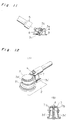
- a battery terminal 55 according to the third embodiment, comprises an electrode-engaging portion 60 formed in the forward end thereof.
- a metal sheet is bent in an annular configuration to form the electrode-engaging portion 60 which is open in the rear end thereof.
- the first tightening plate 64A and the second tightening plate 64B each consisting of a flat plate extending vertically are formed integrally with each free end of the electrode-engaging portion 60.
- the lower end of the second tightening plate 64B disposed on the left side of the battery terminal 55 is bent toward the first tightening plate 64A disposed on the right side of the battery terminal 55 so as to form a tightening substrate 68 consisting of a flat plate.
- the tightening substrate 68 extends toward the right in Fig. 6 in the length of (B) beyond the lower surface of the first tightening plate 64A.
- the tightening substrate 68 has a bolt opening 70 formed at a position located beyond the lower surface of the first tightening plate 64A.
- a bolt 78 is inserted upward into the bolt opening 70.
- a locking strip 72 projects downward from the rear end of the tightening substrate 68 so that the locking strip 72 locks the bolt 78.
- the right end of the tightening substrate 68 is bent upward at an acute angle with respect to the tightening substrate 68 so as to form an inclined portion 74 opposed to the first tightening plate 64A.
- An electric wire-connecting substrate 62 is formed integrally with the rear end of the second tightening substrate 64B.
- the electric wire-connecting substrate 62 is barrel-shaped and the connecting portion thereof is crimped with electric wires inserted therethrough.
- the rectangular tightening strip 66 separate from the first and second tightening plates 64A and 64B is disposed above the tightening substrate 68 with the tightening strip 66 sandwiched between the first tightening plate 64A and the inclined portion 74. That is, an end of the rectangular tightening strip 66 is in contact with the outer surface of the first tightening plate 64A and the other end thereof is in contact with the inclined portion 74 opposed to the first tightening plate 64A.
- the shorter side (length A shown in Figs. 6 and 8) of the rectangular tightening strip 66 is longer than the length (B), of the tightening substrate 68, in the range between the first tightening plate 64A and the inclined portion 74.
- An elongated groove 76 is formed on the tightening strip 66 in the direction from a position corresponding to the left end of the bolt opening 70 toward the inclined portion 74.
- the bolt 78 is inserted upward through the bolt opening 70 and the elongated groove 76 and then, a nut 80 is tightened downward on the bolt 78 so as to temporarily fix the tightening strip 66 to the tightening substrate 68.
- the tightening strip 66 may be formed in the configurations as shown in Figs. 9A, 9B, and 9C.
- a tightening strip 82 comprises a sliding contact portion 82a which is brought in contact with the first tightening plate 64A and a sliding contact portion 82b which is brought in contact with the inclined portion 74.
- the sliding contact portions 82a and 82b are perpendicular to the bottom surface of the tightening strip 82.
- a tightening strip 84 comprises a sliding contact portion 84a which is brought in contact with the first tightening plate 64A and a sliding contact portion 84b which is brought in contact with the inclined portion 74.
- the sliding contact portion 84a and 84b are upward and form an acute angle with the bottom surface of the tightening strip 84, respectively.
- the sliding contact portions 82a, 82b, 84a, and 84b are formed to prevent the tightening substrate 68 from inclining in tightening the nut 80 on the tightening strips 82 and 84.
- a tightening strip 86 comprises a sliding contact portion 86a which is brought in contact with the first tightening plate 64A and a sliding contact portion 86d which is brought in contact with the inclined portion 74.
- the sliding contact portion 86a is perpendicular to the bottom surface of the tightening strip 86.
- the sliding contact portion 86d is upward and forms an acute angle, with the bottom surface of the tightening strip 86, which is equal to the angle formed between the inclined portion 74 and the tightening substrate 68. In this manner, the bottom surface of the tightening strip 86 and sliding contact portion 86d are parallel with the tightening substrate 68 and the inclined portion 74, respectively.
- the bolt 78 to be installed on the battery terminal 55 according to the third embodiment may be a stud bolt, similarly to the bolt 52 according to the second embodiment.
- the battery post 2 of the battery 1 is inserted into the electrode-engaging portion 60 of the battery terminal 55 in which the tightening strip 66 has been temporarily fixed to the tightening substrate 68.
- the nut 80 is tightened downward on the tightening strip 66 by means of an impact wrench. As a result, the nut 80 is moved downward, thus pressing the tightening strip 66 downward.
- the inclined portion 74 in contact with the tightening strip 66 moving downward functions as a means for moving the tightening strip 66 toward (toward the left) the second tightening plate 64B.
- the first tightening plate 64A is pressed and moved toward the second tightening plate 64B.
- the electrode-engaging portion 60 moves in the closing direction thereof is pressed against the battery post 2.
- the battery terminal 55 is fixed to the battery post 2 as shown in Fig. 8.
- the nut is tightened downward on the bolt vertically disposed.
- the elongated groove is moved along the bolt so as to move the tightening strip downward along the inclined portion.
- the tightening force acting downward is divided into the force acting in the direction in which the first tightening plate moves toward the second tightening plate and the force acting in the downward direction. That is, the electrode-engaging portion of the battery terminal can be pressed securely against the battery post and fixed thereto by tightening the nut downward on the bolt.
- the nut can be tightened downward on the bolt not horizontally but vertically. Therefore, the battery terminal can be installed on the battery post with a high efficiency.
- the impact wrench does not interfere with other parts in installing the battery terminal on the battery post and thus a short circuit can be prevented from occurring. Further, the battery terminal can be reliably fixed to the battery post.
Landscapes
- Connection Of Batteries Or Terminals (AREA)
- Connections By Means Of Piercing Elements, Nuts, Or Screws (AREA)
Applications Claiming Priority (2)
| Application Number | Priority Date | Filing Date | Title |
|---|---|---|---|
| JP41571/92 | 1992-06-17 | ||
| JP1992041571U JP2594027Y2 (ja) | 1992-06-17 | 1992-06-17 | バッテリー・ターミナル |
Publications (3)
| Publication Number | Publication Date |
|---|---|
| EP0575181A2 true EP0575181A2 (fr) | 1993-12-22 |
| EP0575181A3 EP0575181A3 (fr) | 1995-01-04 |
| EP0575181B1 EP0575181B1 (fr) | 1997-10-22 |
Family
ID=12612133
Family Applications (1)
| Application Number | Title | Priority Date | Filing Date |
|---|---|---|---|
| EP93304748A Expired - Lifetime EP0575181B1 (fr) | 1992-06-17 | 1993-06-17 | Borne de batterie |
Country Status (4)
| Country | Link |
|---|---|
| US (1) | US5290646A (fr) |
| EP (1) | EP0575181B1 (fr) |
| JP (1) | JP2594027Y2 (fr) |
| DE (1) | DE69314700T2 (fr) |
Cited By (2)
| Publication number | Priority date | Publication date | Assignee | Title |
|---|---|---|---|---|
| GB2287587A (en) * | 1994-03-15 | 1995-09-20 | Daimler Benz Ag | A clamp for a vehicle battery |
| EP0807996A1 (fr) * | 1996-05-14 | 1997-11-19 | Sumitomo Wiring Systems, Ltd. | Borne de batterie avec housse protectrice |
Families Citing this family (30)
| Publication number | Priority date | Publication date | Assignee | Title |
|---|---|---|---|---|
| EP0601521B1 (fr) * | 1992-12-07 | 2000-03-08 | Sumitomo Wiring Systems, Ltd. | Cosse de batterie |
| JP2600044Y2 (ja) * | 1993-01-07 | 1999-09-27 | 住友電装株式会社 | バッテリー・ターミナル |
| JPH0668322U (ja) * | 1993-03-09 | 1994-09-22 | 住友電装株式会社 | バッテリー・ターミナル |
| JP2924561B2 (ja) * | 1993-05-25 | 1999-07-26 | 住友電装株式会社 | バッテリー・ターミナル |
| JPH0688050U (ja) * | 1993-05-31 | 1994-12-22 | 住友電装株式会社 | バッテリー・ターミナル |
| EP0969536A3 (fr) * | 1994-03-03 | 2003-10-08 | Japan Storage Battery Company Limited | Batterie |
| US5733152A (en) * | 1996-10-09 | 1998-03-31 | Royal Die & Stamping Co., Inc. | Battery terminal adaptor and connector |
| GB9626641D0 (en) * | 1996-12-21 | 1997-02-12 | Lucas Ind Plc | Vehicle battery post terminal clamp |
| US5885116A (en) * | 1997-02-28 | 1999-03-23 | Wirthco Engineering Co. | Electrical connector |
| US5879202A (en) * | 1997-06-12 | 1999-03-09 | Aluminum Company Of America | Battery terminal connector |
| US6001506A (en) * | 1997-07-30 | 1999-12-14 | Concorde Battery Corporation | Terminal post assembly for lead acid batteries |
| US6492060B1 (en) | 2000-01-18 | 2002-12-10 | Concorde Battery Corporation | Low resistance high conductivity battery terminal |
| US6701998B2 (en) | 2002-03-29 | 2004-03-09 | Water Gremlin Company | Multiple casting apparatus and method |
| US6561855B1 (en) | 2002-04-04 | 2003-05-13 | Alcoa Fujikura Limited | Clamping mechanism for use with a terminal secured to a battery post and incorporating controlled engagement and spring back characteristics |
| US6855008B1 (en) | 2003-10-06 | 2005-02-15 | Royal Die & Stamping Co., Inc. | Fuse holder with adjustable terminals |
| US7338539B2 (en) | 2004-01-02 | 2008-03-04 | Water Gremlin Company | Die cast battery terminal and a method of making |
| US8701743B2 (en) | 2004-01-02 | 2014-04-22 | Water Gremlin Company | Battery parts and associated systems and methods |
| US6932650B1 (en) | 2004-03-25 | 2005-08-23 | Royal Die & Stamping Co., Inc. | Fused battery terminal connector |
| US20060003627A1 (en) * | 2004-07-01 | 2006-01-05 | Erik Freitag | Fused battery terminal connector |
| JP4706901B2 (ja) * | 2005-02-28 | 2011-06-22 | 住友電装株式会社 | バッテリーターミナル |
| DE102007032837B4 (de) * | 2007-07-12 | 2012-10-31 | Eifelwerk Heinrich Stein Gmbh & Co Kg | Batterieklemme |
| KR200447558Y1 (ko) | 2007-12-07 | 2010-02-03 | 김환창 | 축전지용 접속단자 |
| PL2425478T3 (pl) | 2009-04-30 | 2019-04-30 | Water Gremlin Co | Części akumulatora mające elementy utrzymujące i uszczelniające oraz powiązane z nimi sposoby wytwarzania i zastosowanie |
| US8272085B2 (en) * | 2009-10-13 | 2012-09-25 | Justin Finch | Boat hammock installation system |
| US9748551B2 (en) | 2011-06-29 | 2017-08-29 | Water Gremlin Company | Battery parts having retaining and sealing features and associated methods of manufacture and use |
| US9954214B2 (en) | 2013-03-15 | 2018-04-24 | Water Gremlin Company | Systems and methods for manufacturing battery parts |
| WO2015087633A1 (fr) * | 2013-12-12 | 2015-06-18 | 矢崎総業株式会社 | Borne de batterie |
| US9608254B1 (en) | 2016-05-26 | 2017-03-28 | Royal Die & Stamping Co., Inc. | Pull bar battery terminal clamp |
| US10008789B1 (en) | 2017-07-10 | 2018-06-26 | Royal Die & Stamping, Llc | Angled bolt T-bar battery terminal clamp |
| US11283141B2 (en) | 2018-12-07 | 2022-03-22 | Water Gremlin Company | Battery parts having solventless acid barriers and associated systems and methods |
Family Cites Families (9)
| Publication number | Priority date | Publication date | Assignee | Title |
|---|---|---|---|---|
| US2019823A (en) * | 1931-06-09 | 1935-11-05 | Firestone Battery Company | Storage battery box |
| GB418042A (en) * | 1933-08-25 | 1934-10-17 | Chloride Electrical Storage Co | Improvements relating to terminals for electric accumulators |
| BE559606A (fr) * | 1956-09-06 | |||
| US3973820A (en) * | 1973-04-27 | 1976-08-10 | Aktiebolaget Tudor | Terminal post connection especially for storage batteries |
| FR2310487A1 (fr) * | 1975-05-07 | 1976-12-03 | Tritenne Claude | Dispositif de liaison entre une piece lisse de forme conique et une douille de forme correspondante |
| FR2582447B1 (fr) * | 1985-05-23 | 1989-05-26 | Electro Chimie Soc D | Dispositif de connexion pour batterie d'accumulateur electrique |
| DE9004073U1 (de) * | 1990-04-07 | 1990-06-13 | Auto-Kabel Hausen GmbH & Co. Betriebs-KG, 79688 Hausen | Anschlußklemme für Akkumulator o.dgl. |
| JPH0820794B2 (ja) * | 1990-04-25 | 1996-03-04 | キヤノン株式会社 | 帯電部材および該帯電部材を有する接触帯電装置 |
| JPH049736A (ja) * | 1990-04-27 | 1992-01-14 | Mazda Motor Corp | 合金薄膜のサンプリング方法 |
-
1992
- 1992-06-17 JP JP1992041571U patent/JP2594027Y2/ja not_active Expired - Lifetime
-
1993
- 1993-06-14 US US08/075,891 patent/US5290646A/en not_active Expired - Fee Related
- 1993-06-17 DE DE69314700T patent/DE69314700T2/de not_active Expired - Fee Related
- 1993-06-17 EP EP93304748A patent/EP0575181B1/fr not_active Expired - Lifetime
Cited By (4)
| Publication number | Priority date | Publication date | Assignee | Title |
|---|---|---|---|---|
| GB2287587A (en) * | 1994-03-15 | 1995-09-20 | Daimler Benz Ag | A clamp for a vehicle battery |
| US5547403A (en) * | 1994-03-15 | 1996-08-20 | Mercedes-Benz Ag | Battery terminal clamp |
| GB2287587B (en) * | 1994-03-15 | 1997-10-22 | Daimler Benz Ag | A clamp for a vehicle battery terminal clamp |
| EP0807996A1 (fr) * | 1996-05-14 | 1997-11-19 | Sumitomo Wiring Systems, Ltd. | Borne de batterie avec housse protectrice |
Also Published As
| Publication number | Publication date |
|---|---|
| JP2594027Y2 (ja) | 1999-04-19 |
| JPH065106U (ja) | 1994-01-21 |
| EP0575181B1 (fr) | 1997-10-22 |
| EP0575181A3 (fr) | 1995-01-04 |
| US5290646A (en) | 1994-03-01 |
| DE69314700T2 (de) | 1998-05-14 |
| DE69314700D1 (de) | 1997-11-27 |
Similar Documents
| Publication | Publication Date | Title |
|---|---|---|
| EP0575181B1 (fr) | Borne de batterie | |
| US5302142A (en) | Battery terminal | |
| EP0575964B1 (fr) | Borne pour accumulateur | |
| US5302143A (en) | Battery • terminal | |
| US5595511A (en) | Battery terminal | |
| JP2600044Y2 (ja) | バッテリー・ターミナル | |
| US5492780A (en) | Battery terminal clamp | |
| US5562478A (en) | Joint connector and a method of assembling a joint connector | |
| JP3167106B2 (ja) | 端子金具の組付け構造 | |
| US5498178A (en) | Electrical wire connecting fixture | |
| US7281696B2 (en) | Mounting fitting | |
| JP3209107B2 (ja) | バッテリターミナル | |
| JP2582332Y2 (ja) | バッテリー・ターミナル | |
| JP3206410B2 (ja) | 端子金具の組付け構造 | |
| JP2593283Y2 (ja) | バッテリー・ターミナル | |
| JP2587875Y2 (ja) | バッテリー・ターミナル | |
| US5429512A (en) | Terminal arrangement | |
| JPH11102690A (ja) | バッテリーターミナル | |
| JPH0837052A (ja) | 雌形端子金具 | |
| JPH06150987A (ja) | 圧接端子および該端子を用いた被覆電線の接続方法 | |
| JP2551069Y2 (ja) | ワイヤハーネスのプロテクタ | |
| JPH08124550A (ja) | バッテリ端子 | |
| JPH0917414A (ja) | バッテリー端子 | |
| GB2276046A (en) | Eyelet terminal | |
| JP2000077115A (ja) | バッテリーターミナル |
Legal Events
| Date | Code | Title | Description |
|---|---|---|---|
| PUAI | Public reference made under article 153(3) epc to a published international application that has entered the european phase |
Free format text: ORIGINAL CODE: 0009012 |
|
| AK | Designated contracting states |
Kind code of ref document: A2 Designated state(s): DE FR GB |
|
| PUAL | Search report despatched |
Free format text: ORIGINAL CODE: 0009013 |
|
| AK | Designated contracting states |
Kind code of ref document: A3 Designated state(s): DE FR GB |
|
| 17P | Request for examination filed |
Effective date: 19950223 |
|
| 17Q | First examination report despatched |
Effective date: 19951023 |
|
| GRAG | Despatch of communication of intention to grant |
Free format text: ORIGINAL CODE: EPIDOS AGRA |
|
| GRAH | Despatch of communication of intention to grant a patent |
Free format text: ORIGINAL CODE: EPIDOS IGRA |
|
| GRAH | Despatch of communication of intention to grant a patent |
Free format text: ORIGINAL CODE: EPIDOS IGRA |
|
| GRAA | (expected) grant |
Free format text: ORIGINAL CODE: 0009210 |
|
| AK | Designated contracting states |
Kind code of ref document: B1 Designated state(s): DE FR GB |
|
| REF | Corresponds to: |
Ref document number: 69314700 Country of ref document: DE Date of ref document: 19971127 |
|
| ET | Fr: translation filed | ||
| PLBE | No opposition filed within time limit |
Free format text: ORIGINAL CODE: 0009261 |
|
| STAA | Information on the status of an ep patent application or granted ep patent |
Free format text: STATUS: NO OPPOSITION FILED WITHIN TIME LIMIT |
|
| 26N | No opposition filed | ||
| PGFP | Annual fee paid to national office [announced via postgrant information from national office to epo] |
Ref country code: FR Payment date: 19990610 Year of fee payment: 7 |
|
| PGFP | Annual fee paid to national office [announced via postgrant information from national office to epo] |
Ref country code: GB Payment date: 19990616 Year of fee payment: 7 |
|
| PGFP | Annual fee paid to national office [announced via postgrant information from national office to epo] |
Ref country code: DE Payment date: 19990618 Year of fee payment: 7 |
|
| PG25 | Lapsed in a contracting state [announced via postgrant information from national office to epo] |
Ref country code: GB Free format text: LAPSE BECAUSE OF NON-PAYMENT OF DUE FEES Effective date: 20000617 |
|
| GBPC | Gb: european patent ceased through non-payment of renewal fee |
Effective date: 20000617 |
|
| PG25 | Lapsed in a contracting state [announced via postgrant information from national office to epo] |
Ref country code: FR Free format text: LAPSE BECAUSE OF NON-PAYMENT OF DUE FEES Effective date: 20010228 |
|
| REG | Reference to a national code |
Ref country code: FR Ref legal event code: ST |
|
| PG25 | Lapsed in a contracting state [announced via postgrant information from national office to epo] |
Ref country code: DE Free format text: LAPSE BECAUSE OF NON-PAYMENT OF DUE FEES Effective date: 20010403 |