EP0575199A2 - Système pour visualiser des données - Google Patents
Système pour visualiser des données Download PDFInfo
- Publication number
- EP0575199A2 EP0575199A2 EP93304795A EP93304795A EP0575199A2 EP 0575199 A2 EP0575199 A2 EP 0575199A2 EP 93304795 A EP93304795 A EP 93304795A EP 93304795 A EP93304795 A EP 93304795A EP 0575199 A2 EP0575199 A2 EP 0575199A2
- Authority
- EP
- European Patent Office
- Prior art keywords
- viewing
- point
- pixel values
- volume data
- viewing ray
- Prior art date
- Legal status (The legal status is an assumption and is not a legal conclusion. Google has not performed a legal analysis and makes no representation as to the accuracy of the status listed.)
- Withdrawn
Links
Images


Classifications
-
- G—PHYSICS
- G06—COMPUTING OR CALCULATING; COUNTING
- G06T—IMAGE DATA PROCESSING OR GENERATION, IN GENERAL
- G06T15/00—Three-dimensional [3D] image rendering
- G06T15/10—Geometric effects
- G06T15/40—Hidden part removal
-
- G—PHYSICS
- G06—COMPUTING OR CALCULATING; COUNTING
- G06T—IMAGE DATA PROCESSING OR GENERATION, IN GENERAL
- G06T15/00—Three-dimensional [3D] image rendering
- G06T15/06—Ray-tracing
Definitions
- the invention relates to a system and method which visualizes three-dimensionally distributed data.
- the invention enables the volume rendering of irregular lattice data at high speed.
- Irregular lattice data is numerical data (volume data) defined on partial solid objects (cells) arranged arbitrarily in a three-dimensional space.
- Volume data of this type is standard in the field of structural analysis and is becoming of wider use also in the field of computational fluid dynamics, as commonly found in the results of finite element analysis.
- volume rendering is a computer graphics technique effective for global visualization of scalar fields defined in a three-dimensional space.
- the polygonal approximation method is designed for the effective use of three-dimensional graphics processors that process existing triangle primitives.
- original volume data is expressed as an aggregate of triangle data.
- colour values and opacity are rated with respect to the vertices of triangles, and the rated results are imaged as an aggregate of triangles with the colour values and opacity at each vertex by use of a graphics processor.
- "A Polygonal Approximation to Direct Scalar Volume Rendering" Shirley, Computer Graphics, Vol. 24 No. 5, pp 63-70, 1990, discloses a polygon approximation method requiring such triangles to have been sorted in advance in the direction of a viewing ray.
- EP-A 92106354.1 discloses a technique for volume rendering three-dimensional data on an irregular grid, such as scientific or engineering simulation results.
- the technique is one in which all cells of the volume data are processed.
- volume rendering it is a general practice to specify the nearest exterior face that intersects with a viewing ray, and to compute pixel values while tracing cells in sequence along the viewing ray.
- An exterior face is defined as a constituent facet of a cell that is shared with no other cell.
- the viewing ray will ultimately exit the volume data area (set of cells) through an exterior face. If the volume data area is concave, the viewing ray travelling outside the volume data area may enter the volume data area again through another exterior face. For this reason, it is generally necessary to further judge intersections with other exterior faces, even with regard to viewing rays that are temporarily travelling outside the volume data area.
- the intersection test must be conducted for each viewing ray, and the computation time for such intersection tests notably contributes to overall volume rendering time.
- the present invention provides a data visualisation system for transforming volume data into colour and opacity information
- a data visualisation system for transforming volume data into colour and opacity information
- a further aspect of the present invention provides a data visualisation method for transforming volume data into colour and opacity information comprising the steps of storing data defining at least two polyhedrons the vertices of which being the points to which said volume data is distributed; identifying the exterior facets from the constituent facets of said polyhedrons that form the boundary of said volume data which face either toward or counter to a viewing point; designating one of said identified facets; determining a viewing ray travelling through said view point, a pixel on a projection surface and a point on said designated facet; determining for said viewing ray each polyhedron occurring between the point of intersection of said viewing ray and said designated facet and the point of intersection of said viewing ray and a further exterior facet; generating colour and opacity information for said viewing ray on the basis of said volume data distributed to the vertices of said determined polyhedrons; determining pixel values on the basis of generated said colour and opacity information generation.
- a further embodiment of the present invention may provide a data visualiser for transforming data distributed over a specified area of three-dimensional space into colour and opacity information and displays said data in graphical form on the basis of said colour and opacity information
- said data visualiser comprising: a means for storing information that defines two or more polyhedrons having as their vertices the respective points to which said data is distributed; a means for selecting the ones that form the boundaries of said area and face toward a viewing point from among the constituent facets of said polyhedrons and sorting the ones thus selected according to distance from the viewing point, or otherwise selecting the ones that face counter to a viewing point and sorting the ones thus selected according to distance from the viewing point; a means for specifying said selected constituent facets in said sorting order and carrying out the following processing: (a) means for determining a viewing ray travelling through a viewing point, a pixel on a projection surface and a point on a constituent facet; (b) means for determining each polyhedron occurring between the point of intersection
- a still further embodiment of the present invention may provide a data visualization method by which data distributed over a specified area of three-dimensional space is transformed into colour and opacity information and said data is displayed in graphics on the basis of said colour and opacity information, said data visualization method comprising the steps of: selecting the ones that form the boundaries of said area and face toward a viewing point from among the constituent facets of two or more polyhedrons having as their vertices the respective points to which said data is distributed and sorting the ones thus selected according to distance from the viewing point, or otherwise selecting the ones that face counter to a viewing point and sorting the ones thus selected according to distance from the viewing point; designating said selected constituent facets in said sorting order and carrying out the following processing: (a) determining a viewing ray travelling through a viewing point, a pixel on a projection surface, and a point on a constituent facet, (b) determining each polyhedron occurring between the point of intersection of the corresponding viewing ray and the corresponding constituent facet and the point of intersection of the corresponding
- exterior faces whose normals are directed toward a viewing ray are sorted in the direction of the viewing ray and are arranged in order of proximity to the viewing ray. This corresponds to the case where the order of viewing ray searching is from front to back (FTB) along a viewing ray.
- exterior faces whose normals are directed counter to the viewing ray are sorted in the opposite direction to the viewing ray and are arranged in order of remoteness from the viewing ray.
- the exterior faces thus sorted are then fetched in sequence, and each surface is subjected to scan conversion on a screen.
- points of intersection are determined on the assumption that a viewing ray will intersect with the corresponding exterior face within the range where this surface exists.
- Related pixel values are then computed until the viewing ray goes out of the volume data area, while tracing the cells within the volume data area with these points of intersection as points of departure.
- the result is stored in a frame buffer for each pixel before proceeding to the processing of the next exterior face. If the volume data area is concave, a re-entry is made through another exterior face on the same viewing ray.
- the values in the frame buffer serve as initial values for pixel value computation in such a reentry.
- the frame buffer values thus finally obtained become the results of volume rendering.
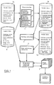
- FIG 1 is a general block diagram of a data visualiser according to the presen invention.
- the data visualiser achieves high-speed volume rendering on the basis of irregular lattice data, and consists of a preprocessor 1, an exterior face sorting subsystem 2, an exterior face scan conversion subsystem 3, and a brightness computing subsystems 4 as shown in Figure 1.
- the preprocessor 1 includes a gradient computing subsystem 1a, a distance computing subsystem lb, and a coordinate transformation subsystem lc. Each subsystem will be detailed later.
- Each subsystem is supplied as input/output with primary volume data 5a, secondary volume data 5b, tertiary volume data 5c, a rendering table 6, and frame buffers 7.
- Each subsystem is a module operating under the control of an IBM 3090/VM system, and the input/output of these subsystems occupies an area of the storage space of the IBM 3090.
- the primary volume data 5a consists of a tetrahedron list 8, lattice point information 9, and exterior face data 10. These are basically the same as those described in Koyamada et al's article, "Volume Rendering Method for Finite Element Method Results - Air Flow Visualization in a Clean Room," Transactions of Information Processing Society of Japan, Vol 32 No 5, pp 560-569.
- the tetrahedron list 8 consists of tetrahedral cell constituent lattice point identification and adjacent tetrahedral cell identification.
- the lattice point information 9 comprises lattice point coordinates and scalar data for each lattice point, which are denoted as X,Y,Z;S.
- the above-mentioned primary volume data 5a is processed by the preprocessor 1, so that secondary volume data 5b is generated.
- the secondary volume data 5b is processed by the sorting subsystem 2, so that tertiary volume data 5c is generated.
- the rendering table 6 comprises a colour table, an opacity table, and camera data.
- the range from the maximum to the minimum of scalar data values is divided into suitable intervals, which are each represented as a serial natural number (ID).
- ID serial natural number
- the ratios of colours (red, green, and blue) and opacity (as an index of the difficulty of transmission of light) are described in correspondence to each ID.
- camera data it is necessary to describe the information (a viewing point, a view reference point, image size, and an up vector to be transformed to the Y-axis of a screen coordinate system) required for the determination of a matrix of transformation to the screen coordinate system and the number of sampling points to be arranged along a viewing ray.
- the frame buffers 7 store interim results or final results (red, green and blue) of brightness computations, as will be described later. For FTB only, these buffers store the interim results of opacity computations accumulated as a viewing ray advances. A storage capacity of eight bits is required to store each component (red, green, blue, and opacity) per pixel. The size of the buffers depends on the image size described as camera data.
- the gradient computing subsystem 1a computes a gradient vector (denoted as "VX, VY, VZ") for each lattice point on the basis of the lattice point IDs of a tetrahedral cell, lattice point coordinates, and scalar data for each lattice point.
- the results of the computation for each tetrahedral cell are distributed to each lattice point.
- a total of the results of the computations for each tetrahedral cell is calculated. The total is divided by the number of cells connected to each lattice point, to determine an average.
- the distance computing subsystem 1b computes the distance from a viewing point, as described in the camera data, of each lattice point and stores the result in memory as distance data.
- the coordinate transformation subsystem generates a screen coordinate system by multiplying lattice point coordinates described in the global coordinate system by a coordinate transformation matrix created on the basis of the camera data.
- "Computer Display Aided Graphics Processing Engineering” Fujio Yamaguchi, Nikkan Kogyo Shinbunsha, pp 161-172, discloses a method for creating such a coordinate transformation matrix.
- secondary volume data 5b is generated by the gradient computing subsystem 1a, distance computing subsystem lb, and coordinate transformation subsystem 1c mentioned above.
- the sections enclosed in rectangles in block 5b represent newly generated data.
- the sorting subsystem 2 rearranges the values of the exterior face data according to distance from a viewing point in an ascending order. Tertiary volume data 5c is thus generated. The section enclosed in a rectangle in block 5c shows modified data.
- the scan conversion subsystem 3 expands data concerning a triangle whose vertices are each represented in a screen coordinate system in a sequence of points whose coordinate values on a screen plane are integers. This subsystem will be detailed later.
- the brightness computing subsystem 4 computes brightness values (R, G, B) and opacity ⁇ (for FTB) at screen coordinates output from the scan conversion subsystem 3 by reference to a given tetrahedral model rendering table and stores the results in the frame buffers 7. The computation of brightness and opacity will be detailed later.
- a point of intersection is computed by a digital differential analyzer on the assumption that a viewing ray will intersect with the exterior face.
- scan conversion Such methods of computing points of intersection, inclusive of DDAs, are termed scan conversion.
- BTF scan conversion is effected in ascending order of priorities determined in the sorting subsystem 2
- FTB scan conversion is effected in descending order of priorities.
- Exterior face scan conversion is conducted in the following way.
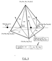
- FIG. 3 there is shown in plan view an exterior face (triangle), having a straight line drawn through the second vertex, parallel to the X-axis, so that the exterior face is divided into two parts and a fourth vertex is added.
- V1 the vertex with the lowest Y coordinate
- V4 the vertex with the highest Y coordinate
- V2 and V3 the two vertices in the same scanning line (a straight line with a constant y) between V1 and V4 are named V2 and V3, where V2 is less than V3 in terms of X coordinates.
- the brightness computing subsystem 4 computes brightness values from a point (x, y), x being an integer, within the range x s ⁇ x ⁇ x e , where x s is the point of intersection of side V1V2 and x e is the point of intersection of side V1V3 in a manner described hereinafter.
- [p] denotes the least integer greater than or equal to p, and ((p)) denotes the greatest integer not exceeding P.
- the brightness values are determined as follows: Pixel values are computed from a point of intersection obtained by scan conversion as a point of departure while tracing the cells in the volume data until a viewing ray goes out of the volume data.
- the discrete brightness equations given below are solved while searching for tetrahedral cells including point (x,y) in succession in the direction of a viewing ray or in the opposite direction departing from a tetrahedral cell interfacing with an exterior face under scan conversion.
- Such searching for tetrahedral cells may be continued until the viewing ray reaches an exterior face, by reference to adjacent cell information included in the given tetrahedral model.
- interpolational computation of gradient vector, scalar data, and distance data is carried out at each point of intersection (entry point and exit point) of a tetrahedral cell, including a sampling point, with a ray of light.
- the area coordinates of these points on a triangular surface, including an entry point and an exit point must be determined in advance. These area coordinates are used as weights on the lattice point data in doing interpolational computation.
- a gradient vector and scalar date are computed by dividing the above-mentioned data by the distance from an entry point to a sampling point or the distance from a sampling point to an exit point. This computation is carried out by making use of the principle that scalar data is linearly distributed in any direction within a tetrahedron.
- Brightness values (ri,gi,bi) are computed on the basis of data values (Si) interpolationally computed at each sampling point, a gradient vector (Vxi, Vyi, Vzi), a suitable optical model, and a colour table.
- Opacity ⁇ i is determined from data values interpolationally computed at each sampling point in light of an opacity table.
- V2,V3,V4 volume rendering images are created on a screen.
- this invention consists of sorting exterior faces facing toward a viewing ray or sorting exterior faces facing counter to a viewing ray, determining pixels on a projection plane corresponding to those exterior faces by scan conversion in the sorting order, computing brightness values along the viewing ray passing through these pixels until the viewing ray goes out of the volume data area, and thus determining pixel values.
- a viewing ray may enter the volume data area again having already left the volume data area previously. In such a case, similar computation is carried out with respect to the boundaries of the entry point and the result of the computation is added to the previous value, so accurate brightness values can be computed.
- the invention obviates the need to run a test as to whether a viewing ray intersects with a boundary or exterioue face, though it entails scan conversion in exterior face units. Moreover, this invention obviates the need to run a test as to whether a viewing ray enters the volume data area again, and thus enables brightness values to be computed accurately and easily.
Landscapes
- Engineering & Computer Science (AREA)
- Physics & Mathematics (AREA)
- Computer Graphics (AREA)
- General Physics & Mathematics (AREA)
- Theoretical Computer Science (AREA)
- Geometry (AREA)
- Image Generation (AREA)
Applications Claiming Priority (2)
| Application Number | Priority Date | Filing Date | Title |
|---|---|---|---|
| JP4159909A JPH087799B2 (ja) | 1992-06-19 | 1992-06-19 | データ視覚化装置および方法 |
| JP159909/92 | 1992-06-19 |
Publications (2)
| Publication Number | Publication Date |
|---|---|
| EP0575199A2 true EP0575199A2 (fr) | 1993-12-22 |
| EP0575199A3 EP0575199A3 (fr) | 1995-06-14 |
Family
ID=15703819
Family Applications (1)
| Application Number | Title | Priority Date | Filing Date |
|---|---|---|---|
| EP93304795A Withdrawn EP0575199A3 (fr) | 1992-06-19 | 1993-06-18 | Système pour visualiser des données. |
Country Status (3)
| Country | Link |
|---|---|
| US (1) | US5742293A (fr) |
| EP (1) | EP0575199A3 (fr) |
| JP (1) | JPH087799B2 (fr) |
Families Citing this family (18)
| Publication number | Priority date | Publication date | Assignee | Title |
|---|---|---|---|---|
| TW304254B (fr) | 1994-07-08 | 1997-05-01 | Hitachi Ltd | |
| EP0740272A2 (fr) * | 1995-04-28 | 1996-10-30 | Sun Microsystems, Inc. | Procédé et dispositif pour représenter rapidement une image à trois dimensions |
| JP3323738B2 (ja) * | 1996-06-14 | 2002-09-09 | インターナショナル・ビジネス・マシーンズ・コーポレーション | ボリューム・データ計算方法及び装置並びにボリューム・データ可視化方法及び装置 |
| US6181348B1 (en) * | 1997-09-22 | 2001-01-30 | Siemens Corporate Research, Inc. | Method for selective volume visualization via texture mapping |
| US6356262B1 (en) * | 1998-04-16 | 2002-03-12 | International Business Machines Corporation | System and method for fast polyhedral cell sorting |
| WO2001044869A1 (fr) | 1999-12-16 | 2001-06-21 | Nikon Corporation | Monture a baionnette |
| US6574356B1 (en) * | 2000-04-19 | 2003-06-03 | National Science Council | Method for three-dimensional image reconstruction of basal ganglion |
| US7295200B2 (en) * | 2000-11-07 | 2007-11-13 | F. Poszat Hu, Llc | Computer generated hologram display system |
| US20050114831A1 (en) * | 2001-04-18 | 2005-05-26 | Andres Callegari | Volume body renderer |
| EP2362346B1 (fr) * | 2001-04-18 | 2013-07-10 | Landmark Graphics Corporation | Procédé et produit de programme d'ordinateur pour le rendu d'un volume |
| KR100436815B1 (ko) * | 2001-12-24 | 2004-06-23 | 한국전자통신연구원 | 실시간 렌더링을 위한 하드웨어 그래픽 가속장치 내 연산최적화 시스템 및 그 방법 |
| WO2005081683A2 (fr) * | 2004-02-12 | 2005-09-09 | Pixar | Procede et appareil destines a mettre en antememoire une geometrie multirevolution basee sur des differentiels de rayon |
| KR100629516B1 (ko) * | 2004-09-21 | 2006-09-28 | 삼성전자주식회사 | 색역 경계 검출장치 및 이를 이용하는 매핑 장치 그리고그 방법 |
| US9024949B2 (en) * | 2004-10-13 | 2015-05-05 | Sony Corporation | Object representation using distance functions |
| US7965291B1 (en) * | 2006-11-03 | 2011-06-21 | Nvidia Corporation | Isosurface extraction utilizing a graphics processing unit |
| US20140313195A1 (en) * | 2008-02-29 | 2014-10-23 | Cherif Atia Algreatly | 3D Model Mapping |
| JP5161991B2 (ja) * | 2011-03-25 | 2013-03-13 | 株式会社東芝 | 画像処理装置 |
| CN115797601B (zh) * | 2022-09-08 | 2023-10-27 | 上海新迪数字技术有限公司 | 一种Brep三维模型的中面自动提取方法及系统 |
Family Cites Families (7)
| Publication number | Priority date | Publication date | Assignee | Title |
|---|---|---|---|---|
| US4952922A (en) * | 1985-07-18 | 1990-08-28 | Hughes Aircraft Company | Predictive look ahead memory management for computer image generation in simulators |
| FR2610752B1 (fr) * | 1987-02-10 | 1989-07-21 | Sagem | Procede de representation de l'image en perspective d'un terrain et systeme pour sa mise en oeuvre |
| US5038302A (en) * | 1988-07-26 | 1991-08-06 | The Research Foundation Of State University Of New York | Method of converting continuous three-dimensional geometrical representations into discrete three-dimensional voxel-based representations within a three-dimensional voxel-based system |
| US4985856A (en) * | 1988-11-10 | 1991-01-15 | The Research Foundation Of State University Of New York | Method and apparatus for storing, accessing, and processing voxel-based data |
| GB8828342D0 (en) * | 1988-12-05 | 1989-01-05 | Rediffusion Simulation Ltd | Image generator |
| US5113357A (en) * | 1989-05-18 | 1992-05-12 | Sun Microsystems, Inc. | Method and apparatus for rendering of geometric volumes |
| US5555352A (en) * | 1991-04-23 | 1996-09-10 | International Business Machines Corporation | Object-based irregular-grid volume rendering |
-
1992
- 1992-06-19 JP JP4159909A patent/JPH087799B2/ja not_active Expired - Lifetime
-
1993
- 1993-06-18 EP EP93304795A patent/EP0575199A3/fr not_active Withdrawn
-
1996
- 1996-02-26 US US08/607,048 patent/US5742293A/en not_active Expired - Lifetime
Non-Patent Citations (4)
| Title |
|---|
| IBM TECHNICAL DISCLOSURE BULLETIN, vol. 32,no. 11, April 1990 NEW YORK US, pages 57-60, XP 000097607 'RENDERING ALGORITHM FOR VISUALIZING VOXEL AND SURFACE DATA' * |
| IEEE COMPUTER GRAPHICS AND APPLICATIONS, vol. 10,no. 2, March 1990 NEW YORK US, pages 33-40, XP 000115962 LEVOY 'A HYBRID RAY TRACER FOR RENDERING POLYGON AND VOLUME DATA' * |
| JOURNAL OF VISUALIZATION AND COMPUTER ANIMATION, vol. 3,no. 2, April 1992 LONDON, pages 65-83, MIYAZAWA AND KOYAMADA 'A HIGH-SPEED INTEGRATED RENDERER FOR INTERPRETING MULTIPLE 3D VOLUME DATA' * |
| PROCEEDINGS OF THE FIRST IEEE CONFERENCE ON VISUALIZATION, 23 October 1990 NEW-YORK US, pages 36-44, XP 000244840 MONTINE 'A PROCEDURAL INTERFACE FOR VOLUME RENDERING' * |
Also Published As
| Publication number | Publication date |
|---|---|
| EP0575199A3 (fr) | 1995-06-14 |
| JPH0636046A (ja) | 1994-02-10 |
| US5742293A (en) | 1998-04-21 |
| JPH087799B2 (ja) | 1996-01-29 |
Similar Documents
| Publication | Publication Date | Title |
|---|---|---|
| EP0575199A2 (fr) | Système pour visualiser des données | |
| AU600515B2 (en) | Method and system for solid modelling | |
| CA2225017C (fr) | Methode et appareil d'affichage rapide d'images de structures complexes creees par ordinateur | |
| US6359623B1 (en) | Method and apparatus for performing scan conversion in a computer graphics display system | |
| US4888583A (en) | Method and apparatus for rendering an image from data arranged in a constructive solid geometry format | |
| US5579454A (en) | Three dimensional graphics processing with pre-sorting of surface portions | |
| Weiler et al. | Hidden surface removal using polygon area sorting | |
| US5689287A (en) | Context-preserving display system using a perspective sheet | |
| US5926182A (en) | Efficient rendering utilizing user defined shields and windows | |
| US5600763A (en) | Error-bounded antialiased rendering of complex scenes | |
| EP0311081B1 (fr) | Appareil et procédé d'affichage pour graphiques d'ordinateur en trois dimensions | |
| EP0638875B1 (fr) | Appareil et méthode pour génération d'animation en 3 dimensions | |
| US4697178A (en) | Computer graphics system for real-time calculation and display of the perspective view of three-dimensional scenes | |
| EP0422866B1 (fr) | Méthode et appareil de génération d'images | |
| WO1990006561A1 (fr) | Generateur d'images | |
| JPH02210587A (ja) | 高速イメージ表現装置 | |
| JPH07120434B2 (ja) | ボリュームレンダリングを行う方法及び装置 | |
| US4930091A (en) | Triangle classification setup method and apparatus for 3-D graphics display system | |
| EP0435492B1 (fr) | Méthode et système pour l'affichage d'objet tri-dimensionnel | |
| CA2043176C (fr) | Quantification de l'axe des z pour lignes tridimensionnelles | |
| US5926183A (en) | Efficient rendering utilizing user defined rooms and windows | |
| US8174526B2 (en) | Methods and apparatus for rendering or preparing digital objects or portions thereof for subsequent processing | |
| US4992962A (en) | Area set operation apparatus | |
| KR100298789B1 (ko) | 그래픽 처리에 있어서 클리핑 처리방법 | |
| EP0583088A2 (fr) | Méthode et dispositif de visualisation graphique |
Legal Events
| Date | Code | Title | Description |
|---|---|---|---|
| PUAI | Public reference made under article 153(3) epc to a published international application that has entered the european phase |
Free format text: ORIGINAL CODE: 0009012 |
|
| AK | Designated contracting states |
Kind code of ref document: A2 Designated state(s): DE FR GB |
|
| 17P | Request for examination filed |
Effective date: 19940429 |
|
| PUAL | Search report despatched |
Free format text: ORIGINAL CODE: 0009013 |
|
| AK | Designated contracting states |
Kind code of ref document: A3 Designated state(s): DE FR GB |
|
| STAA | Information on the status of an ep patent application or granted ep patent |
Free format text: STATUS: THE APPLICATION HAS BEEN WITHDRAWN |
|
| 18W | Application withdrawn |
Withdrawal date: 19980109 |