EP0575239B1 - Druckgasvorrichtung zum einmaligen Versprühen einer begrenzten Menge eines flüssigen Materials in fein verteilten Teilchen - Google Patents
Druckgasvorrichtung zum einmaligen Versprühen einer begrenzten Menge eines flüssigen Materials in fein verteilten Teilchen Download PDFInfo
- Publication number
- EP0575239B1 EP0575239B1 EP93401526A EP93401526A EP0575239B1 EP 0575239 B1 EP0575239 B1 EP 0575239B1 EP 93401526 A EP93401526 A EP 93401526A EP 93401526 A EP93401526 A EP 93401526A EP 0575239 B1 EP0575239 B1 EP 0575239B1
- Authority
- EP
- European Patent Office
- Prior art keywords
- plug
- substance
- compressed gas
- tank
- powder material
- Prior art date
- Legal status (The legal status is an assumption and is not a legal conclusion. Google has not performed a legal analysis and makes no representation as to the accuracy of the status listed.)
- Expired - Lifetime
Links
- 239000000463 material Substances 0.000 title claims description 31
- 238000005507 spraying Methods 0.000 title claims description 5
- 239000012530 fluid Substances 0.000 title claims description 4
- 239000000126 substance Substances 0.000 claims description 42
- 239000000843 powder Substances 0.000 claims description 35
- 230000004888 barrier function Effects 0.000 claims description 22
- 230000006835 compression Effects 0.000 claims description 13
- 238000007906 compression Methods 0.000 claims description 13
- 239000007787 solid Substances 0.000 claims description 11
- 230000000694 effects Effects 0.000 claims description 8
- 230000035939 shock Effects 0.000 claims description 7
- 238000006073 displacement reaction Methods 0.000 claims description 6
- 239000007788 liquid Substances 0.000 claims description 6
- 239000004698 Polyethylene Substances 0.000 claims description 4
- -1 polyethylene Polymers 0.000 claims description 4
- 229920000573 polyethylene Polymers 0.000 claims description 4
- 239000012815 thermoplastic material Substances 0.000 claims description 3
- 230000000717 retained effect Effects 0.000 claims description 2
- 238000007789 sealing Methods 0.000 description 6
- 239000004033 plastic Substances 0.000 description 4
- 229920003023 plastic Polymers 0.000 description 4
- 235000021183 entrée Nutrition 0.000 description 3
- 230000014759 maintenance of location Effects 0.000 description 3
- 238000004026 adhesive bonding Methods 0.000 description 2
- 239000011324 bead Substances 0.000 description 2
- 239000003814 drug Substances 0.000 description 2
- 229920001971 elastomer Polymers 0.000 description 2
- 239000000806 elastomer Substances 0.000 description 2
- 239000002184 metal Substances 0.000 description 2
- 230000002093 peripheral effect Effects 0.000 description 2
- 239000011343 solid material Substances 0.000 description 2
- 230000000903 blocking effect Effects 0.000 description 1
- 229940079593 drug Drugs 0.000 description 1
- 229920002457 flexible plastic Polymers 0.000 description 1
- 229920001903 high density polyethylene Polymers 0.000 description 1
- 239000004700 high-density polyethylene Substances 0.000 description 1
- 239000011148 porous material Substances 0.000 description 1
- 239000007921 spray Substances 0.000 description 1
- 229910001220 stainless steel Inorganic materials 0.000 description 1
- 239000010935 stainless steel Substances 0.000 description 1
- 230000001629 suppression Effects 0.000 description 1
- 229920001169 thermoplastic Polymers 0.000 description 1
- 239000004416 thermosoftening plastic Substances 0.000 description 1
- 238000009827 uniform distribution Methods 0.000 description 1
Images


Classifications
-
- B—PERFORMING OPERATIONS; TRANSPORTING
- B05—SPRAYING OR ATOMISING IN GENERAL; APPLYING FLUENT MATERIALS TO SURFACES, IN GENERAL
- B05B—SPRAYING APPARATUS; ATOMISING APPARATUS; NOZZLES
- B05B11/00—Single-unit hand-held apparatus in which flow of contents is produced by the muscular force of the operator at the moment of use
- B05B11/01—Single-unit hand-held apparatus in which flow of contents is produced by the muscular force of the operator at the moment of use characterised by the means producing the flow
- B05B11/06—Gas or vapour producing the flow, e.g. from a compressible bulb or air pump
- B05B11/062—Gas or vapour producing the flow, e.g. from a compressible bulb or air pump designed for spraying particulate material
-
- A—HUMAN NECESSITIES
- A61—MEDICAL OR VETERINARY SCIENCE; HYGIENE
- A61M—DEVICES FOR INTRODUCING MEDIA INTO, OR ONTO, THE BODY; DEVICES FOR TRANSDUCING BODY MEDIA OR FOR TAKING MEDIA FROM THE BODY; DEVICES FOR PRODUCING OR ENDING SLEEP OR STUPOR
- A61M11/00—Sprayers or atomisers specially adapted for therapeutic purposes
- A61M11/02—Sprayers or atomisers specially adapted for therapeutic purposes operated by air or other gas pressure applied to the liquid or other product to be sprayed or atomised
-
- A—HUMAN NECESSITIES
- A61—MEDICAL OR VETERINARY SCIENCE; HYGIENE
- A61M—DEVICES FOR INTRODUCING MEDIA INTO, OR ONTO, THE BODY; DEVICES FOR TRANSDUCING BODY MEDIA OR FOR TAKING MEDIA FROM THE BODY; DEVICES FOR PRODUCING OR ENDING SLEEP OR STUPOR
- A61M15/00—Inhalators
- A61M15/08—Inhaling devices inserted into the nose
-
- A—HUMAN NECESSITIES
- A61—MEDICAL OR VETERINARY SCIENCE; HYGIENE
- A61M—DEVICES FOR INTRODUCING MEDIA INTO, OR ONTO, THE BODY; DEVICES FOR TRANSDUCING BODY MEDIA OR FOR TAKING MEDIA FROM THE BODY; DEVICES FOR PRODUCING OR ENDING SLEEP OR STUPOR
- A61M2202/00—Special media to be introduced, removed or treated
- A61M2202/06—Solids
- A61M2202/064—Powder
-
- A—HUMAN NECESSITIES
- A61—MEDICAL OR VETERINARY SCIENCE; HYGIENE
- A61M—DEVICES FOR INTRODUCING MEDIA INTO, OR ONTO, THE BODY; DEVICES FOR TRANSDUCING BODY MEDIA OR FOR TAKING MEDIA FROM THE BODY; DEVICES FOR PRODUCING OR ENDING SLEEP OR STUPOR
- A61M2205/00—General characteristics of the apparatus
- A61M2205/07—General characteristics of the apparatus having air pumping means
- A61M2205/071—General characteristics of the apparatus having air pumping means hand operated
- A61M2205/073—Syringe, piston type
Definitions
- the present invention relates to a compressed gas device for projecting in finely divided form a single dose of a fluid substance.
- the invention applies to such devices intended to spray a single dose of a medicament in pulverulent solid form or in liquid form.
- Such devices are generally used for nasal spraying.
- the substance reservoir comprises a converging part, which converges towards the outlet orifice, and which constitutes the means for limiting the displacement of the plug towards the outlet orifice of the reservoir.
- the stopper is in the form of a spherical ball, so that there is a non-negligible risk for the ball to obstruct the outlet orifice before all the substance contained in the reservoir is expelled.
- the object of the present invention is to eliminate this drawback.
- the present invention therefore relates to a compressed gas device as defined above, characterized in that said means for limiting the displacement of the plug have means for guaranteeing the passage of the flow of compressed gas when the plug is in its position stop.
- the substance reservoir comprises a converging part, which converges towards the outlet orifice, said converging part constitutes said means for limiting the movement of the plug, and said converging part comprises internal reliefs which constitute said means for guarantee the passage of the compressed gas flow.
- said substance is a solid powder material
- the substance reservoir has a fixed barrier, which maintains the dose of powder material in a position remote from the compressed gas inlet orifice
- said fixed barrier constitutes said means for limiting the movement of the plug
- said means for guaranteeing the passage of the flow of compressed gas comprise at least one opening which crosses said fixed barrier.
- Said fixed barrier may be a membrane-shaped element, advantageously provided with a certain flexibility.
- Said fixed barrier may also comprise a solid central rod provided with at least one axial lateral groove constituting said at least one opening for passage of the flow of compressed gas.
- the stopper has an enlarged heel which cooperates with the narrowed section of the intermediate channel to limit the movement of the stopper towards the reservoir of substance, and said heel has at least one opening which constitutes said means for guaranteeing the passage of the compressed gas flow.
- said stopper when said substance is a solid powdery material, when said means for limiting the movement of the stopper stop the movement of said stopper, said stopper has sufficient kinetic energy to transmit to said powdery material a shock which ensures the disaggregation of said powdery material.
- said substance is a pulverulent solid material
- said substance reservoir comprises a converging part which converges towards the outlet orifice, said convergent part has a shape, and the outlet orifice has a section, adapted to allow the retention of the pulverulent material by vault effect in the vicinity of the outlet orifice, during the manipulation of the device before its actuation.
- said stopper when said means for limiting the movement of the stopper stop the movement of said stopper stop the movement of said stopper, said stopper has sufficient kinetic energy to transmit to said pulverulent material a shock which ensures the disgusting of the pulverulent metariau, and thus facilitates its projection through from the outlet through the compressed gas flow.
- the outlet orifice of the substance reservoir may have a diameter less than or equal to 1.5 mm, possibly less than or equal to 1 mm, possibly less than or equal to 0 , 5 mm.
- the hollow piston is made of a relatively flexible plastic material, such as polyethylene.
- said intermediate channel comprises a liquid reserve, and liquid retention means arranged between the plug and the gas reserve.
- said retention means are a capillary channel.
- the substance is a solid pulverulent material
- the substance reservoir has a fixed barrier which maintains the dose of pulverulent material in a position remote from the compressed gas inlet orifice
- the reservoir of said substance is removable
- the said gas compression means constitute an air pump provided with an inlet valve and an elastic return means
- the said section of reduced section of the intermediate channel has one end which is flared towards the orifice entry of the reservoir
- the stopper is returned by an elastic means for returning the stopper to a position in which it closes said flared end of said section of reduced section
- said flared end has a sufficiently low conicity to allow the plug to be jammed in said flared end under the sole action of the elastic means for returning the plug.
- Said taper can advantageously be less than or equal to 10 °.
- Said fixed barrier can constitute said means for limiting the movement of the plug and said means for guaranteeing the passage of the flow of compressed gas can comprise at least one opening which crosses said fixed barrier.
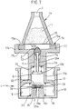
- the device comprises a push-piece 15 which delimits a reservoir 1 containing a substance to be sprayed, for example a powdery solid material.
- a substance to be sprayed for example a powdery solid material.
- This solid powder material will generally be a drug for nasal use.
- the tip 15 extends axially between a front end 15a and a rear end 15b. At its front end 15a, the end piece 15 has an outlet orifice 3, which communicates with the reservoir 1 of substance.
- the tip 15 has an outer radial ring 22, which serves as a fulcrum for the fingers of a user.
- the push-piece 15 comprises a frustoconical wall 9, which converges towards the outlet orifice 3 and which extends between the front end 15a and the outer radial ring 22.
- the push-piece 15 includes a cylindrical wall 16, which extends axially between the ring 22 and the rear end 15b.
- the frustoconical wall 9 has an inner surface in which are formed axial ribs 9b, the usefulness of which will be seen later.
- the push-piece 15 which has just been described can be molded from a thermoplastic material.
- the front end 15a of the push-piece 15 is covered by a cap 30, which can be formed from plastic or any other material, and fixed to the push-piece 15 by tight fitting, snap-fastening, screwing, or any other means.
- the device according to the invention further comprises a piston 17, which is fitted into the cylindrical wall 16 of the push-piece.
- the piston 17 comprises a peripheral sealing lip 17a, which projects radially outside the cylindrical wall 16 in the vicinity of the rear end 15b of the push-piece, and a fixing rod 17b which is fitted into the cylindrical wall 16 of the push-piece 15.
- the fixing rod 17b has an axial central channel 6 which passes through it and which communicates with the reservoir 1 of substance.
- the axial channel has a section 7 of narrowed section, which defines an inlet orifice 2 of the reservoir 1. In the section 7 is forced into a ball or a plug 8 of another shape, so as to close the orifice inlet 2 of the reservoir 1 of substance.
- the piston 17 is advantageously molded from a material relatively flexible thermoplastic, for example polyethylene.
- the ball can be made, for example, of stainless steel or else of high density polyethylene.
- the device according to the invention further comprises a cylinder 18 which can be molded from plastic.
- the cylinder 18 has a bottom 19 and a cylindrical side wall 29 which extends axially between the bottom 19 and an open end 23.
- the peripheral sealing lip 17a of the piston 17 slides with sealing inside the cylindrical side wall 22.
- the piston 17 and the cylinder 18 thus define a compression system 4 which contains a reserve of gas 5, which can be filled with air or another gas.
- the bottom 19 of the cylinder 18 may comprise a central part 19a which projects towards the central channel 6 of the piston, and which is adapted to penetrate said central channel 6, during the actuation of the device, so as to increase the pressure prevailing in the gas reserve 5 during actuation.
- the piston 17 can be made of a flexible material, which allows good sealing of the piston 17 with the cylinder 18 and with the ball 8, and which also allows good tightening. elastic of the ball 8 inside the narrowed section 7.
- the shape of the frustoconical wall 9 and the diameter of the outlet orifice 3 are such that, when the cap is removed, during the handling of the device before its actuation, the dose of powder contained in the reservoir 1 is retained by vault effect inside the tank 1, by a phenomenon similar to that which sometimes occurs accidentally in silos for the storage of powdery materials. In this way, even when the orifice 3 is directed downwards after removal of the cap, the dose of powder contained in the reservoir 1 does not escape through the orifice 3 before the device is actuated.
- the orifice 3 can have a diameter less than or equal to 1.5 mm, advantageously close to 1 mm, possibly less than 1 mm or 0.5 mm, with conventional pharmaceutical powders intended for nasal spraying.
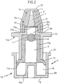
- Figure 2 shows a variant of the device of Figure 1.
- the general structure of the device of Figure 2 is similar to the structure of the device of Figure 1, so that the device of Figure 2 will not be described again in detail.
- the device of FIG. 2 differs from the device of FIG. 1 in that the frusto-conical wall 9 does not have the push-piece 15 does not have an internal rib 9b.
- the push-piece 15 is here formed in two parts, a front part 15c comprising the frustoconical wall 9 and a rear wall 15d comprising the crown 22 and the cylindrical wall 16.
- the frustoconical wall 9 extends axially towards the ring 22 by a cylindrical wall 9d of short length which extends to an axial end 9e, forming an internal shoulder 9f.
- the ring 22 has a cylindrical wall 22a which is adapted to fit into the cylindrical wall 9d.
- the cylindrical wall 9d can be fixed inside the cylindrical wall 22a by force fitting, by snap-fastening, by gluing or by any
- the device also comprises a fine mesh grid 10 which has a periphery 10b fixed by wedging between the shoulder 9f and the cylindrical wall 22a.
- the grid 10 can be formed by a crisscrossing of metal wires secured to one another or it can be produced by a metal or plastic plate pierced with holes 10a.
- the holes 10a are small enough not to be crossed by the powder contained in the reservoir 1. The dose of powder is thus delimited by the frustoconical wall 9 and the grid 10, and it is kept away from the ball 8.
- the ball 8 When the device is actuated, the ball 8 abruptly strikes the grid 10. The cynetic energy accumulated by the ball 10 is sufficient to create a shock which takes off the dose of powder relative to the grid 10, which facilitates the passage of the gas through the grid 10. In addition, the impact has the effect of deagglomerating the powder contained in the reservoir 1, which facilitates subsequent entrainment by the flow of compressed gas. In addition, the shock causes "the devoutness" of the dose of powder around the orifice to exit 3, that is to say the suppression of the arch effect which prevented the exit of the powder through the orifice. 3.
- the grid 10 has a certain flexibility, so that the impact of the ball on the grid causes a deformation which tends to open the meshes or the pores of the grid on the powder side, which favors the passage of air.
- FIG. 3 represents another variant of the device of FIG. 1 which has a neighboring structure, and which will not be described again in detail.
- the device no longer comprises a ball, but a plug 13 which extends towards the gas reserve 5 by a rod 13a provided with a heel 11 projecting radially outwards.
- the heel 11 has passages 11a for the flow of compressed gas.
- the plug 13 is ejected towards the substance reservoir 1, but its movement is limited by the heel 11 which abuts against the section 7 of narrowed section of the intermediate channel 6.
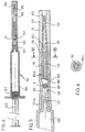
- Figures 4 to 6 show another embodiment of the device according to the invention.
- the device comprises a syringe 104, provided with a cylindrical gas reserve 105 in which slides a piston 117 provided with an actuating rod 123.
- the reservoir 105 and the actuating rod 123 can be molded from plastic; the piston is advantageously made of elastomer.
- the syringe 104 has a capillary outlet channel 121, which is formed in an end tip 122.
- the device further comprises a section of tube 124 which extends axially between a first end 124a and a second end 124b.
- the first end 124a of the tube section 124 is forcibly fitted onto the end nozzle 122 of the syringe 104.
- the tube section 124 defines an intermediate channel 106, having a section 107 of reduced section. A ball is wedged in the section 107 of reduced section, by obstructing said section 107.
- the device further comprises a nozzle 115 which has a cylindrical side wall 116, which is forced into the second end 124b of the tube section 124, said cylindrical wall 116 extending forwardly by a frustoconical wall 109, up to a outlet orifice 103.
- a sleeve 127 of cylindrical external shape is fitted onto the side wall 116 and the frustoconical wall 109 in order to prevent a user from being able to injure himself with the pointed end of the frustoconical wall 109.
- the sleeve 127 is capped with a cap (not shown) during storage.
- the frustoconical wall 109 and the rod 126 delimit a reserve of powder 101 which has an inlet orifice 102.
- the groove 126a has a sufficiently small dimension so that the powder contained in the reservoir 101 does not enter said groove 126a, and the outlet orifice 103 has a sufficiently small dimension so that the powder does not leave the orifice during the manipulation of the device before its actuation, creating a arch effect, as previously seen.
- the tube section 124, the ball 8 and the capillary channel 121 define a reserve of liquid 120, which is expelled at the same time as the powder during actuation.
- the capillary channel 121 has a sufficiently small diameter to prevent the liquid from the reserve 120 from entering the gas reserve 105.
- the device shown in Figure 7 is a variant of Figure 2 which is designed to be rechargeable.
- the device of Figure 7 comprises a removable tank 1, which is formed in two parts.
- the tank 1 comprises a front part 1a and a rear part 1b, which are assembled by force fitting, by gluing, by snap-fastening or by any other means, trapping a grid 10 between them, similar to that described with reference to the figure.
- the front part 1a of the reservoir 1 has a generally frustoconical shape, and has an outlet orifice 3.
- the reservoir 1 is designed to contain a substance in powder form, the grid is designed to retain said pulverulent substance inside the front part 1a, and the shape of the front part 1a as well as the section of the outlet orifice 3 are provided to prevent the accidental release of the powder during handling of the device.
- the rear part 1b of the reservoir 1 comprises an outer radial ring 22.
- the device further comprises an air pump 4, comprising a cylinder 18 and a piston 17 sliding in the cylinder.
- the piston and the cylinder define a pump chamber 5, and a return spring 30 is interposed between them.
- the cylinder 18 has a bottom 19, provided with an air inlet opening 19b which communicates with an inlet valve.
- the inlet orifice 19b opens out inside the cylinder 18, at the center of a substantially radial surface 35.
- a sealing bead 35a is formed around the outlet of the inlet orifice 19b.
- the radial surface 35 is surrounded by an axial cylindrical wall 36, which receives a valve holder 33.
- a flat seal 34 made of elastomer, is trapped between the valve holder 33 and the radial surface 35, and said seal 34 is adapted to apply tightly to the sealing bead 35a when an overpressure prevails inside the cylinder 18.
- inlet valves are disclosed in document EP-A-0 377 536, and in Corresponding American patent US Pat. No. 4,966,535.
- the bottom 19 has reliefs 19c for centering the spring 30.
- the piston 17 has a hollow rod 17b, which defines an intermediate channel between the air pump 4 and the reservoir 1.
- the rod 17b extends axially towards the reservoir 1 up to a crown 17c, which extends radially towards the 'outside.
- the crown 17c is extended axially towards the reservoir 1 by a cylindrical side wall 17b, which extends to latching means 17e.
- the latching means 17 can be, for example, an inner rib.
- the ring 22 of the reservoir 1 is received inside the cylindrical side wall 17d, and it is kept in contact with the ring 17c by the latching means 17e.
- the ring 22 of the reservoir 12 is in sealed contact with the cylindrical side wall 17d or the ring 17c.
- the piston 17 is formed from a relatively flexible material, such as polyethylene, so that the seal between the crown 22 and the cylindrical side wall 17 can be obtained by elastic clamping of the crown 22 inside the cylindrical wall 17d.
- the intermediate channel 6 has a section 7 of narrowed section in the vicinity of the reservoir 1.
- the section 7 defines an inlet orifice 2 of the reservoir 1.
- the section 7 of narrowed section has in the vicinity of the reservoir 1, an enlarged end 7b flared towards the reservoir 1.
- the end 7b also has a conical shape, with a taper angle ⁇ preferably less than or equal to 10 °.
- the section 7 of narrowed section also defines a shoulder 7a, directed towards the bottom 19 of the cylinder 18.
- the device further comprises a plug 13, which is wedged in the flared end 7b of the section 7.
- a rod 13a is force-fitted into said plug 13, and said rod extends axially towards the bottom 19 of the cylinder 19, up to 'to a collar 13b, disposed inside the widest part of the intermediate channel 6.
- a return spring 31 of the plug is disposed between the shoulder 7a and the collar 13b.
- the return spring 31 is generally of low stiffness, so as not to hinder the movement of the plug 13 towards the reservoir 1 during actuation.
- the rod 13a has a length sufficient to allow the plug 13 to strike the grid 10 during actuation.
- the plug 13 is wedged in said flared end 7b after each actuation, under the sole action of the return spring 31 of the plug, despite the low stiffness of said spring 31.
Landscapes
- Health & Medical Sciences (AREA)
- Engineering & Computer Science (AREA)
- Life Sciences & Earth Sciences (AREA)
- Anesthesiology (AREA)
- Biomedical Technology (AREA)
- Heart & Thoracic Surgery (AREA)
- Hematology (AREA)
- Animal Behavior & Ethology (AREA)
- General Health & Medical Sciences (AREA)
- Public Health (AREA)
- Veterinary Medicine (AREA)
- Bioinformatics & Cheminformatics (AREA)
- Pulmonology (AREA)
- Otolaryngology (AREA)
- Containers And Packaging Bodies Having A Special Means To Remove Contents (AREA)
Claims (22)
- Druckgasvorrichtung zum Versprühen einer Einzeldosis eines Fluids in fein verteilter Form, die folgende Bestandteile umfaßt:- einen Behälter (1, 101), der die Einzeldosis enthält und eine Eintrittsöffnung (2, 102) für das Druckgas sowie eine Ausgangsöffnung (3, 103) aufweist,- von Hand betätigbare Einrichtungen (4, 104) zum Komprimieren des Gases, wobei diese Einrichtungen (4, 104) zum Komprimieren des Gases einen Gasvorratsraum (5, 105) umfassen, der mit der Eintrittsöffnung (2, 102) des Behälters (1, 101) vermittels eines Verbindungskanals (6, 16) in Verbindung steht, der einen Abschnitt (7, 107) mit verengtem Querschnitt aufweist, wobei dieser Abschnitt mit verengtem Querschnitt durch einen Pfropfen (8, 103) dicht verschlossen ist, der in den Abschnitt mit verengtem Querschnitt in der Weise eingeklemmt ist, daß dann, wenn der Druck des im Gasvorratsraum (5, 105) enthaltenen Gases einen vorbestimmten Grenzwert erreicht, der Pfropfen (8, 103) aus dem Abschnitt (7, 107) mit verengtem Querschnitt zum Behälter (1, 101) der Substanz hin herausgedrückt wird und dabei den Verbindungskanal (6, 106) freigibt, undwobei die Vorrichtung Mittel (9, 10, 11, 112) zum Begrenzen der Verschiebung des Pfropfens (8, 13) in Richtung der Ausgangsöffnung des Substanzbehälters umfaßt, die somit eine Anschlagsposition des Pfropfens definieren, dadurch gekennzeichnet, daß die Mittel (9, 10, 11, 112) zum Begrenzen der Verschiebung des Pfropfens Mittel (9b, 10a, 11a, 112a) umfassen, die das Hindurchtreten des Druckgasstroms sicherstellen, wenn sich der Pfropfen in seiner Anschlagsposition befindet.
- Vorrichtung nach Anspruch 1, bei der der Substanzbehälter (1) einen konvergierenden Teil (9) umfaßt, der zur Ausgangsöffnung (3) hin konvergiert, wobei der konvergierende Teil (9) die Mittel zum Begrenzen der Bewegung des Pfropfens bildet und der konvergierende Teil (9) innere Erhabenheiten (9c) aufweist, die die Mittel (9c) bilden, die das Hindurchströmen des Druckgasstromes sicherstellen.
- Vorrichtung nach Anspruch 1, bei der die Substanz ein festes pulverförmiges Material ist und bei der der Substanzbehälter (1) eine feste Barriere (10, 112) umfaßt, die die Dosis des pulverförmigen Materials in einer von der Eintrittsöffnung (2) für das Druckgas entfernten Position hält, wobei die feste Barriere die Mittel zum Begrenzen der Bewegung des Pfropfens bildet und wobei die Mittel, die das Hindurchtreten des Druckgasstromes sicherstellen, wenigstens eine Öffnung (10a, 112a) umfassen, die sich durch die feste Barriere hindurch erstreckt.
- Vorrichtung nach Anspruch 3, bei der dann, wenn der Pfropfen (8) in Berührung mit der festen Barriere (10, 112) tritt, der Pfropfen eine kinetische Energie besitzt, die ausreicht, daß der Stoß des Pfropfens auf die feste Barriere eine Ablösung der Dosis des pulverförmigen Materials von der festen Barriere zur Folge hat.
- Vorrichtung nach Anspruch 3 oder 4, bei der die feste Barriere ein Element in Form einer Membran (10) ist.
- Vorrichtung nach Anspruch 5, bei der die Membran (10) eine gewisse Flexibilität besitzt.
- Vorrichtung nach Anspruch 3 oder 4, bei der die feste Barriere eine zentrale Vollstange (112) umfaßt, die wenigstens eine seitliche, sich in axialer Richtung erstreckende Rille (112a) aufweist, die wenigstens eine Durchgangsöffnung für den Druckgasstrom bildet.
- Vorrichtung nach Anspruch 1, bei der der Pfropfen (13) einen vergrößerten Ansatz (11) umfaßt, der mit dem Abschnitt mit verengtem Querschnitt (7) des Verbindungskanals (6) zusammenwirkt, um die Bewegung des Pfropfens zum Substanzbehälter (1) hin zu begrenzen, und wobei dieser Ansatz wenigstens eine Öffnung (11a) umfaßt, die die Mittel zum Sicherstellen des Durchgangs des Druckgasstromes bildet.
- Vorrichtung nach Anspruch 1, bei der die Substanz ein festes pulverförmiges Material ist und bei der dann, wenn die Mittel (9, 10, 11, 112) zum Begrenzen der Bewegung des Pfropfens die Verschiebung dieses Pfropfens anhalten, der Pfropfen eine kinetische Energie besitzt, die ausreicht, um auf das pulverförmige Material einen Stoß zu übertragen, der eine Desagglomeration des besagten pulverförmigen Materials sicherstellt.
- Vorrichtung nach Anspruch 1, bei der die Substanz ein festes pulverförmiges Material ist und der Behälter (1, 101) für die Substanz einen konvergierenden Teil (9, 109) umfaßt, der zur Austrittsöffnung (3, 103) hin konvergiert, wobei der konvergierende Teil eine Form und die Austrittsöffnung einen Querschnitt besitzen, die geeignet sind, das Zurückhalten des pulverförmigen Materials durch einen Gewölbeeffekt in der Nachbarschaft der Ausgangsöffnung während der Handhabung der Vorrichtung vor ihrer Betätigung zu ermöglichen.
- Vorrichtung nach Anspruch 10, bei der dann, wenn die Mittel (9, 10, 11, 112) zur Begrenzung der Bewegung des Pfropfens die Verschiebung dieses Pfropfens anhalten, der Pfropfen eine kinetische Energie besitzt, die ausreichend ist, um auf das pulverförmige Material einen Stoß auszuüben, der die Aufhebung des Gewölbeeffektes des pulverförmigen Materials sicherstellt und somit sein Ausstoßen durch die Ausgangsöffnung (3, 103) durch den Druckgasstrom zu erleichtern.
- Vorrichtung nach Anspruch 10, bei der die Austrittsöffnung (3, 103) einen Durchmesser von kleiner/gleich 1,5 mm besitzt.
- Vorrichtung nach Anspruch 10, bei der die Austrittsöffnung (3, 103) einen Durchmesser kleiner/gleich 1 mm besitzt.
- Vorrichtung nach Anspruch 10, bei der die Austrittsöffnung (3, 103) einen Durchmesser kleiner/gleich 0,5 mm besitzt.
- Vorrichtung nach Anspruch 1, bei der- der Behälter (3) für die Substanz in einem Druckansatzstück (15) enthalten ist, das einen hinteren hohlzylindrischen Teil (16) aufweist, der mit der Druckgas-Eintrittsöffnung (2) des Behälters (3) in Verbindung steht,- die Einrichtungen (4) zum Komprimieren des Gases einen hohlen Kolben (17) umfassen, der in den hinteren Teil (16) des Druckansatzstückes (15) eingesetzt ist, sowie einen mit einem Boden (19) versehenen Zylinder (18), der in axialer Richtung auf dem Kolben (17) gleitet, und bei der- der hohle Kolben (17) den Verbindungskanal (6) umgrenzt.
- Vorrichtung nach Anspruch 15, bei der der hohle Kolben (17) aus einem nachgiebigen thermoplastischen Material hergestellt ist.
- Vorrichtung nach Anspruch 16, bei der das nachgiebige thermoplastische Material Polyäthylen ist.
- Vorrichtung nach Anspruch 1, bei der der Verbindungskanal (106) einen Flüssigkeitsvorrat (120) und Mittel zum Zurückhalten der Flüssigkeit (121) umfaßt, die zwischen dem Pfropfen und dem Gas-Vorratsraum (4) angeordnet sind.
- Vorrichtung nach Anspruch 18, bei der die Rückhaltemittel von einem Kapillarkanal (121) gebildet werden.
- Vorrichtung nach Anspruch 1, bei der die Substanz ein festes pulverförmiges Material ist, der Behälter für die Substanz (1) eine feste Barriere (10) umfaßt, die die Dosis des pulverförmigen Materials in einer von der Druckgas-Eintrittsöffnung (2) entfernten Position hält, der Behälter (1) für die Substanz abnehmbar ist, bei der die Einrichtungen zum Komprimieren des Gases (4) eine Luftpumpe bilden, die mit einem Eintrittsventil (33, 34) und einer elastischen Rückholvorrichtung (30) versehen ist, bei der der Abschnitt (7) mit vermindertem Querschnitt des Verbindungskanals (6) einen Endbereich (7b) umfaßt, der zur Eintrittsöffnung (2) des Behälters hin erweitert ist, bei der der Pfropfen (13) von einer elastischen Pfropfen-Rückholeinrichtung (31) in eine Position vorgespannt ist, in der er den erweiterten Endbereich (7b) des Verbindungskanals (7) verschließt und bei der der erweiterte Endbereich (7b) eine ausreichend schwache Konizität besitzt, um das Einklemmen des Pfropfens (13) in den erweiterten Endbereich allein unter der Wirkung der elastischen Pfropfen-Rückholvorrichtung (31) zu ermöglichen.
- Vorrichtung nach Anspruch 20, bei der die Konizität weniger oder gleich 10° ist.
- Vorrichtung nach Anspruch 20 oder 21, bei der die feste Barriere (10) die Mittel zum Begrenzen der Bewegung des Pfropfens bildet und bei der die Einrichtungen, die das Hindurchtreten des Druckgasstromes sicherstellen, wenigstens eine Öffnung (10a) umfassen, die sich durch die feste Barriere hindurch erstreckt.
Applications Claiming Priority (2)
| Application Number | Priority Date | Filing Date | Title |
|---|---|---|---|
| FR9207250 | 1992-06-16 | ||
| FR9207250A FR2692174B1 (fr) | 1992-06-16 | 1992-06-16 | Dispositif à gaz comprimé pour projeter sous forme finement divisée une dose unique d'une substance fluide. |
Publications (2)
| Publication Number | Publication Date |
|---|---|
| EP0575239A1 EP0575239A1 (de) | 1993-12-22 |
| EP0575239B1 true EP0575239B1 (de) | 1996-10-23 |
Family
ID=9430772
Family Applications (1)
| Application Number | Title | Priority Date | Filing Date |
|---|---|---|---|
| EP93401526A Expired - Lifetime EP0575239B1 (de) | 1992-06-16 | 1993-06-15 | Druckgasvorrichtung zum einmaligen Versprühen einer begrenzten Menge eines flüssigen Materials in fein verteilten Teilchen |
Country Status (4)
| Country | Link |
|---|---|
| US (1) | US5328099A (de) |
| EP (1) | EP0575239B1 (de) |
| DE (1) | DE69305577T2 (de) |
| FR (1) | FR2692174B1 (de) |
Families Citing this family (31)
| Publication number | Priority date | Publication date | Assignee | Title |
|---|---|---|---|---|
| FR2731684B1 (fr) * | 1995-03-17 | 1997-05-30 | Sanofi Sa | Dispositif de stockage et de distribution d'un produit, tel un produit cosmetique ou un parfum |
| CA2218879A1 (en) * | 1995-05-12 | 1996-11-14 | Genentech, Inc. | Coarse spray delivery of functional biologic materials |
| AUPN976496A0 (en) * | 1996-05-10 | 1996-05-30 | Glaxo Wellcome Australia Ltd | Unit dose dispensing device |
| US6200288B1 (en) | 1997-08-26 | 2001-03-13 | Queen's University At Kingston | Everting toroid device for insertion into a body cavity |
| US5954688A (en) * | 1997-08-26 | 1999-09-21 | Queen's University At Kingston | Everting toroid device for delivering a drug into a body cavity |
| CN1106888C (zh) * | 1998-03-10 | 2003-04-30 | 瓦卢瓦股份有限公司 | 容器、容器的灌注方法及容器中流体制品的分配装置 |
| FR2775963B1 (fr) * | 1998-03-10 | 2000-05-19 | Valois Sa | Dispositif pour distribuer unitairement une dose de produit a l'aide d'un ecoulement de gaz sous pression |
| AU5149200A (en) | 1999-05-21 | 2000-12-12 | Mallinckrodt, Inc. | Contrast media resuspension device and method |
| EP1092447B1 (de) | 1999-10-14 | 2004-01-07 | Becton Dickinson and Company | Nasales Verabreichungsgerät mit Zerstäuberdüse |
| FR2837800B1 (fr) * | 2002-03-26 | 2005-06-24 | Valois Sa | Distributeur de produit fluide |
| GB0215904D0 (en) * | 2002-07-09 | 2002-08-21 | Team Holdings Uk Ltd | Drug delivery system and method |
| US20040069817A1 (en) * | 2002-10-15 | 2004-04-15 | Jacques Daniel R. | Hand pump foamer |
| US20050220721A1 (en) * | 2004-03-17 | 2005-10-06 | Kablik J J | Anti-adhesion spraying |
| TW200824693A (en) * | 2006-08-28 | 2008-06-16 | Jazz Pharmaceuticals Inc | Pharmaceutical compositions of clonazepam and methods of use thereof |
| US9061096B2 (en) | 2009-12-16 | 2015-06-23 | Water Pik, Inc. | Powered irrigator for sinus cavity rinse |
| US8991660B2 (en) * | 2009-12-16 | 2015-03-31 | Water Pik, Inc. | Squeeze bottle for sinus cavity rinse |
| US8888752B2 (en) * | 2009-12-16 | 2014-11-18 | Water Pik, Inc. | Bottle for sinus cavity rinse |
| CA2817482C (en) * | 2010-11-12 | 2018-10-30 | Wolfe Tory Medical, Inc. | Atomizer for nasal therapy |
| CA2825541C (en) * | 2011-01-31 | 2020-06-02 | Shin Nippon Biomedical Laboratories, Ltd. | Intranasal delivery devices |
| FR3007991B1 (fr) * | 2013-07-05 | 2017-05-05 | Aptar France Sas | Dispositif de distribution de produit fluide ou pulverulent. |
| FR3007992B1 (fr) * | 2013-07-05 | 2018-01-26 | Aptar France Sas | Dispositif de distribution de produit fluide ou pulverulent. |
| FR3007990B1 (fr) * | 2013-07-05 | 2018-03-23 | Aptar France Sas | Dispositif de distribution de produit fluide ou pulverulent. |
| FR3046552B1 (fr) * | 2016-01-07 | 2018-02-16 | Aptar France Sas | Dispositif de distribution nasale de poudre. |
| WO2019054121A1 (ja) * | 2017-09-15 | 2019-03-21 | 株式会社新日本科学 | 薬剤保管用のノズル付きカートリッジとその噴射器、および鼻腔用粉状薬剤施薬装置 |
| US10617832B2 (en) | 2017-11-22 | 2020-04-14 | Southwest Research Institute | High precision, low dose atomizer |
| CN110354350B (zh) * | 2019-07-18 | 2021-12-10 | 南京医科大学附属逸夫医院 | 一种改良的雾化器 |
| FR3106487B1 (fr) * | 2020-01-27 | 2023-02-10 | Aptar France Sas | Dispositif de distribution de produit pulvérulent |
| FR3121047B1 (fr) | 2021-03-29 | 2023-07-14 | Aptar France Sas | Dispositif de distribution nasale de poudre |
| US12414916B2 (en) | 2021-06-10 | 2025-09-16 | Belhaven BioPharma Inc. | Dry powder formulations of epinephrine and associated methods |
| US11617716B2 (en) | 2021-06-10 | 2023-04-04 | Belhaven BioPharma Inc. | Dry powder formulations of epinephrine and associated methods |
| US12005185B2 (en) | 2021-12-17 | 2024-06-11 | Belhaven BioPharma Inc. | Medical counter measures including dry powder formulations and associated methods |
Family Cites Families (11)
| Publication number | Priority date | Publication date | Assignee | Title |
|---|---|---|---|---|
| US3127110A (en) * | 1964-03-31 | Sprinkler head | ||
| US2223611A (en) * | 1939-05-22 | 1940-12-03 | Richard E Gross | Syringe |
| US2515193A (en) * | 1945-11-19 | 1950-07-18 | Frank R Chester | Powder sprayer |
| US2718987A (en) * | 1951-12-12 | 1955-09-27 | Shulton Inc | Powder dispensing and applying device |
| US2731299A (en) * | 1953-05-01 | 1956-01-17 | Aladdin Ind Inc | Filtering fuel nozzle for pressure stoves and lanterns |
| CH518744A (de) * | 1970-01-30 | 1972-02-15 | Ciba Geigy Ag | Vorrichtung zur Applikation von pulverförmigen Substanzen |
| US4017007A (en) * | 1973-12-26 | 1977-04-12 | Ciba-Geigy Corporation | Single dose air pressure operated dispenser |
| SE7415243L (de) * | 1973-12-26 | 1975-06-27 | Ciba Geigy Ag | |
| US4162749A (en) * | 1978-02-27 | 1979-07-31 | Risdon Manufacturing Company | Squeezable dispenser with outlet closure |
| FR2450208A1 (fr) * | 1979-02-28 | 1980-09-26 | Oreal | Dispositif de fermeture a buse basculable pour recipient pressurise |
| DE4042708C2 (de) * | 1990-02-22 | 2003-06-12 | Pfeiffer Erich Gmbh & Co Kg | Austragvorrichtung für Medien mit einer handbetätigten Pumpe |
-
1992
- 1992-06-16 FR FR9207250A patent/FR2692174B1/fr not_active Expired - Fee Related
-
1993
- 1993-06-15 EP EP93401526A patent/EP0575239B1/de not_active Expired - Lifetime
- 1993-06-15 DE DE69305577T patent/DE69305577T2/de not_active Expired - Lifetime
- 1993-06-16 US US08/077,059 patent/US5328099A/en not_active Expired - Lifetime
Also Published As
| Publication number | Publication date |
|---|---|
| DE69305577T2 (de) | 1997-05-28 |
| DE69305577D1 (de) | 1996-11-28 |
| FR2692174B1 (fr) | 1994-08-19 |
| EP0575239A1 (de) | 1993-12-22 |
| FR2692174A1 (fr) | 1993-12-17 |
| US5328099A (en) | 1994-07-12 |
Similar Documents
| Publication | Publication Date | Title |
|---|---|---|
| EP0575239B1 (de) | Druckgasvorrichtung zum einmaligen Versprühen einer begrenzten Menge eines flüssigen Materials in fein verteilten Teilchen | |
| EP1064102B1 (de) | Behälter, verfahren zur befüllung dieses behälter und abgabevorrichtung für das im behälter enthaltene pulver | |
| EP0773835B1 (de) | Tragbare vorrichtung zum spritzen einer fliessfähigen substanz mittels druckluft | |
| EP0721573B1 (de) | Dosiergerät zur abgabe von konstanten einheitlichen dosen | |
| EP0954485B1 (de) | Vorrichtung zur abgabe vom fliessfähigen produkt mit verschlussvorrichtung | |
| EP0591365B1 (de) | Vorrichtung zum Spritzen einer vorbestimmten Dosis eines Mediums und Verfahren zum Füllen dieser Vorrichtung | |
| EP1185376A1 (de) | Abgabevorrichtung für medien | |
| FR3098420A1 (fr) | Dispositif de distribution nasale de poudre | |
| FR3117046A1 (fr) | Dispositif de distribution de doses de poudre | |
| EP4237050A1 (de) | Vorrichtung zur abgabe eines flüssigen produkts | |
| EP0437131A1 (de) | Vordruck-Handpumpe zum zerstäuben einer Flüssigkeit, insbesondere eines Parfüms | |
| FR3135069A1 (fr) | Dispositif de distribution de produit fluide et son procédé d'amorçage | |
| FR2746676A1 (fr) | Dispositif de distribution d'une dose unique de produit fluide | |
| EP3206968B1 (de) | Vorrichtung zur ausgabe eines kosmetischen produktes in aerosolform, zugehörige anordnung und verfahren | |
| EP0477083B1 (de) | Vordruck-Handpumpe | |
| WO2017051127A1 (fr) | Valve pour embout a obturateur | |
| FR2784969A1 (fr) | Reservoir pourvu d'un dispositif de fermeture et de remplissage et dispositif de distribution de produit fluide comportant un tel reservoir | |
| EP0879191B1 (de) | Vorrichtung zum dosieren eines fliessfähigen mediums in einem hermetisch geschlossenen behälter | |
| FR2775963A1 (fr) | Dispositif pour distribuer unitairement une dose de produit a l'aide d'un ecoulement de gaz sous pression | |
| FR2678906A1 (fr) | Dispositif pour projeter une dose predeterminee d'un produit fluide, et son procede de remplissage. | |
| FR2612571A1 (fr) | Distributeur a pompe pour petites doses precises de produit fluide | |
| FR2780388A1 (fr) | Reservoir de produit pulverulent et procede de remplissage d'un tel reservoir | |
| EP3797002B1 (de) | Flüssigproduktspender | |
| EP4064927B1 (de) | Vorrichtung zur ausgabe eines flüssigen oder pastösen produkts | |
| FR3106487A1 (fr) | Dispositif de distribution de produit pulvérulent |
Legal Events
| Date | Code | Title | Description |
|---|---|---|---|
| PUAI | Public reference made under article 153(3) epc to a published international application that has entered the european phase |
Free format text: ORIGINAL CODE: 0009012 |
|
| AK | Designated contracting states |
Kind code of ref document: A1 Designated state(s): DE FR GB IT |
|
| 17P | Request for examination filed |
Effective date: 19940621 |
|
| GRAG | Despatch of communication of intention to grant |
Free format text: ORIGINAL CODE: EPIDOS AGRA |
|
| 17Q | First examination report despatched |
Effective date: 19960311 |
|
| GRAH | Despatch of communication of intention to grant a patent |
Free format text: ORIGINAL CODE: EPIDOS IGRA |
|
| GRAH | Despatch of communication of intention to grant a patent |
Free format text: ORIGINAL CODE: EPIDOS IGRA |
|
| GRAA | (expected) grant |
Free format text: ORIGINAL CODE: 0009210 |
|
| AK | Designated contracting states |
Kind code of ref document: B1 Designated state(s): DE FR GB IT |
|
| REF | Corresponds to: |
Ref document number: 69305577 Country of ref document: DE Date of ref document: 19961128 |
|
| ITF | It: translation for a ep patent filed | ||
| GBT | Gb: translation of ep patent filed (gb section 77(6)(a)/1977) |
Effective date: 19970124 |
|
| RAP2 | Party data changed (patent owner data changed or rights of a patent transferred) |
Owner name: VALOIS S.A. |
|
| REG | Reference to a national code |
Ref country code: FR Ref legal event code: TP Ref country code: FR Ref legal event code: CD Ref country code: FR Ref legal event code: CA |
|
| PLBE | No opposition filed within time limit |
Free format text: ORIGINAL CODE: 0009261 |
|
| STAA | Information on the status of an ep patent application or granted ep patent |
Free format text: STATUS: NO OPPOSITION FILED WITHIN TIME LIMIT |
|
| 26N | No opposition filed | ||
| REG | Reference to a national code |
Ref country code: GB Ref legal event code: IF02 |
|
| PGFP | Annual fee paid to national office [announced via postgrant information from national office to epo] |
Ref country code: IT Payment date: 20100622 Year of fee payment: 18 |
|
| PGFP | Annual fee paid to national office [announced via postgrant information from national office to epo] |
Ref country code: GB Payment date: 20100521 Year of fee payment: 18 Ref country code: FR Payment date: 20100802 Year of fee payment: 18 Ref country code: DE Payment date: 20100614 Year of fee payment: 18 |
|
| GBPC | Gb: european patent ceased through non-payment of renewal fee |
Effective date: 20110615 |
|
| PG25 | Lapsed in a contracting state [announced via postgrant information from national office to epo] |
Ref country code: IT Free format text: LAPSE BECAUSE OF NON-PAYMENT OF DUE FEES Effective date: 20110615 |
|
| REG | Reference to a national code |
Ref country code: FR Ref legal event code: ST Effective date: 20120229 |
|
| REG | Reference to a national code |
Ref country code: DE Ref legal event code: R119 Ref document number: 69305577 Country of ref document: DE Effective date: 20120103 |
|
| PG25 | Lapsed in a contracting state [announced via postgrant information from national office to epo] |
Ref country code: FR Free format text: LAPSE BECAUSE OF NON-PAYMENT OF DUE FEES Effective date: 20110630 Ref country code: DE Free format text: LAPSE BECAUSE OF NON-PAYMENT OF DUE FEES Effective date: 20120103 |
|
| PG25 | Lapsed in a contracting state [announced via postgrant information from national office to epo] |
Ref country code: GB Free format text: LAPSE BECAUSE OF NON-PAYMENT OF DUE FEES Effective date: 20110615 |