EP0575249B1 - Einrichtung zur elastischen Lagerung von Statorwickelköpfe - Google Patents
Einrichtung zur elastischen Lagerung von Statorwickelköpfe Download PDFInfo
- Publication number
- EP0575249B1 EP0575249B1 EP93401542A EP93401542A EP0575249B1 EP 0575249 B1 EP0575249 B1 EP 0575249B1 EP 93401542 A EP93401542 A EP 93401542A EP 93401542 A EP93401542 A EP 93401542A EP 0575249 B1 EP0575249 B1 EP 0575249B1
- Authority
- EP
- European Patent Office
- Prior art keywords
- clamping plate
- ring
- supports
- crown
- fixed
- Prior art date
- Legal status (The legal status is an assumption and is not a legal conclusion. Google has not performed a legal analysis and makes no representation as to the accuracy of the status listed.)
- Expired - Lifetime
Links
- 238000004804 winding Methods 0.000 title claims abstract description 4
- 229910001220 stainless steel Inorganic materials 0.000 claims description 4
- 239000010935 stainless steel Substances 0.000 claims description 4
- 239000003822 epoxy resin Substances 0.000 claims description 3
- 229920000647 polyepoxide Polymers 0.000 claims description 3
- 125000006850 spacer group Chemical group 0.000 claims description 3
- 238000007789 sealing Methods 0.000 claims description 2
- 239000011152 fibreglass Substances 0.000 claims 1
- 238000013016 damping Methods 0.000 description 11
- 239000000463 material Substances 0.000 description 3
- 239000006096 absorbing agent Substances 0.000 description 2
- 230000000694 effects Effects 0.000 description 2
- 239000003365 glass fiber Substances 0.000 description 2
- 230000035939 shock Effects 0.000 description 2
- 239000011324 bead Substances 0.000 description 1
- 239000000112 cooling gas Substances 0.000 description 1
- 238000006073 displacement reaction Methods 0.000 description 1
- 230000004907 flux Effects 0.000 description 1
- 238000003780 insertion Methods 0.000 description 1
- 230000037431 insertion Effects 0.000 description 1
- 238000003754 machining Methods 0.000 description 1
- 239000002184 metal Substances 0.000 description 1
- 230000000284 resting effect Effects 0.000 description 1
- 238000000926 separation method Methods 0.000 description 1
- 238000003466 welding Methods 0.000 description 1
- 239000002023 wood Substances 0.000 description 1
Images

Classifications
-
- H—ELECTRICITY
- H02—GENERATION; CONVERSION OR DISTRIBUTION OF ELECTRIC POWER
- H02K—DYNAMO-ELECTRIC MACHINES
- H02K3/00—Details of windings
- H02K3/42—Means for preventing or reducing eddy-current losses in the winding heads, e.g. by shielding
-
- H—ELECTRICITY
- H02—GENERATION; CONVERSION OR DISTRIBUTION OF ELECTRIC POWER
- H02K—DYNAMO-ELECTRIC MACHINES
- H02K3/00—Details of windings
- H02K3/46—Fastening of windings on the stator or rotor structure
- H02K3/50—Fastening of winding heads, equalising connectors, or connections thereto
- H02K3/505—Fastening of winding heads, equalising connectors, or connections thereto for large machine windings, e.g. bar windings
Definitions
- the invention relates to a device for elastic support of the stator coil heads of a rotating electric machine, in particular for turbo alternators.
- stator coil heads need to be resiliently supported. The reason is that they are subjected to stresses and deformations due to possible short circuits, current surges, thermal expansion or other causes.
- the stator coil heads are supported by a support cage formed by several rings concentric with the magnetic circuit and resting on insulating supports distributed regularly around the stator.
- the support cage is fixed to the stator clamping plate by means of brackets, generally made of non-magnetic stainless steel (see Figure 1).
- the brackets have their first sides fixed to the clamping plate, with the insertion of a damping screen. They have their second sides fixed to the insulating supports of the support cage. The flexibility of the brackets gives the desired elasticity to the stator coil heads.
- brackets pose a number of problems. Their angular distribution on the clamping plate is difficult to obtain with precision. During operation, some brackets can break depending on the stresses and thus create asymmetries harmful to the proper functioning of the machine. There is also a lack of certainty on the supports of the brackets, poor support causing an offset and vibrations of the winding.
- DE-A-2 161 139 relates to an elastic support device for the stator coil heads of a rotating electric machine, comprising a first ring mounted, with cold clearance, on the clamping plate, a support cage having supports of which one end is guided in radial displacement in grooves shaped in the crown, and the other end is secured to a second crown
- the device according to the invention aims to improve the mechanical strength of the support and the setting of the coil heads stator. This is achieved by replacing the metal brackets used so far with a crown having a spring effect.
- crown instead of brackets allows the separation of the fixing functions of the damping screen and fixing of the support.
- This crown can be made of non-magnetic stainless steel, but also of a material formed of woven glass fiber and coated with epoxy resin.
- the device described above is difficult to assemble, and the sliding connection existing between the supports and the first ring appreciably affects the support of the coil heads.
- the device according to the invention aims to improve the mechanical strength of the support and the setting of the stator coil heads. This is achieved by fixing the supports on the first ring, and removing the second ring.
- the invention relates to a device for elastic support of the stator coil heads of a rotary electric machine, comprising a support cage fixed by means of supports on the clamping plate of the machine, the device comprising means for elastic fixing of the supports on the clamping plate, said elastic fixing means comprising at least one crown, the crown being made integral with the clamping plate by securing means, according to the invention, the supports are fixed on said crown by bolts and nuts, said supports having a hole cooperating with a positioning pin.
- An advantage of this new structure is the gain obtained in assembly time.
- the different elements are also easier to assemble.
- the device may further comprise a damping screen disposed between the clamping plate and the crown and fixed to the clamping plate independently of the crown.
- the damping screen has fewer fixing holes. It is therefore simpler to carry out and its assembly can be done more quickly.
- the means for securing the crown to the clamping plate may include centering sleeves. This allows the rapid and precise removal of the crown on the clamping plate.
- the crown can advantageously be made up of several sectors joined together, three or four for example. This allows the sectors to be machined in a single operation by simple superposition.
- the crown requires fewer fixing points on the clamping plate than the brackets. So we can just use the handling holes of the clamping plate to fix the elastic crown.
- the clamping plate therefore has a limited number of holes. Its machining is therefore simpler and faster.
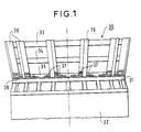
- Figure 1 is a side view of a support cage 30 according to the prior art and fixed on the clamping plate 31 of the stator 32.
- the cage consists of three rings 33, 34 and 35 in wood for example, concentric to the stator axis and regularly spaced.
- the rings are supported by supports 36, shown here in a simplified manner, regularly spaced around the clamping plate.
- Each support 36 is fixed to the clamping plate by two brackets 37. This fixing is ensured by screws with interposing of the damping screen 38 which serves as protection against magnetic and electric flux.
- the brackets have their first sides fixed to the clamping plate and their second sides fixed to the insulating supports 36.
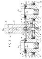
- the section of Figure 2 was made along the median axis 1 of the crown (see Figure 3).
- the sockets On the side opposite the clamping plate, the sockets have a shoulder 6 for receiving the crown.
- the crown 3 is pierced with chamfered holes 7 in which the ends of restricted diameter of the sockets engage.
- the insulating supports 8 are fixed on the elastic crown 3 regularly.
- FIG. 3 there is shown in broken lines 9 the location of an insulating support on the crown, halfway between two counterbores 5.
- the damping screen 10 is arranged between the clamping plate 2 and the elastic crown 3. It is placed at a certain distance from the clamping plate by means of spacers 11. The damping screen is pierced with holes 13 allowing the sleeves to pass through. centering 4.
- Threaded holes are provided in the clamping plate: threaded holes 14 at the bottom of the countersinks 5 for fixing the elastic crown, and threaded holes 15 for fixing the damping screen.
- the support cage To mount the support cage on the machine, first fix the shock absorber screen on the clamping plate. Separate the insulating supports and the retaining rings are mounted on the elastic crown. The elastic crown fitted with the retaining cage is then attached to the clamping plate equipped with the damping screen and the centering sleeves.
- the shock absorber screen 10 is fixed by means of the clamping screws 16 passing through the screen and the spacers 11 to be screwed into the threaded holes 15.
- the head of the screw 16 can be permanently connected to the screen 10 thanks to to a brake 25 fixed to the screen by a screw 12.
- the fixing of the insulating supports 8 on the crown 3 can be done by a connection of the screw-nut type.
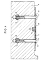
- Two bolts 17 pass through the crown 3 and a part of the support 8 to open into a hole 18 machined transversely relative to the bolts (see FIG. 4).
- the insulating support 8 is fixed to the crown by means of the bolts 17 and the nuts cylindrical 19 with interposition of a double brake 20 which ensures a final connection.
- a pin 21 ensures the positioning of the insulating support.
- FIG. 3 a better distinction is made between the holes 23 for the passage of the bolts 17 in the elastic crown and the hole 22 for the passage of the pin 21.
- the holes 22 and 23 may be of identical diameter. The pin is locked on the elastic crown when the double brake 20 is in position under the heads of the screws 17.
- the fixing of the fitted crown on the clamping plate is done by the screws 24 passing through the washers 29 and the sockets 4 to be screwed into the threaded holes 14.
- a final fixing can be ensured by weld beads 28 as shown. in FIG. 2.
- Welding points 39 definitively fix each screw 24 to its washer 29.
- the axis of the screw 16 coincides with the axis of the pin 21.
- Figure 3 shows that the elastic crown was made from four identical sectors joined by welds 26.
- the elasticity of the crown 3 is due to the large distance separating its fixing points on the clamping plate and also to the nature of the material used to make it.
- non-magnetic stainless steel or a material formed of woven glass fiber coated with epoxy resin will be used.
- Sealing washers 27 of the statified type can be installed around the sockets 4, between the clamping plate 2 and the damping screen 10. They thus prevent leaks of the cooling gas circulating in the space confined between the clamping plate and the damping screen.
- the crown effect gives better mechanical strength to the support assembly and provides less vibration on the involutes and on the connections, better resistance to stalling thereof and increased longevity of the machine.
- the forces are transmitted directly to the clamping plate. Thanks to the invention, the adjustments between the clamping plate and the support cage are eliminated.
- This new design is adaptable to all types of alternators, whether they have flat clamping plates or molded clamping plates. On the molded clamping plates, it is possible to adjust the supports between the outer crown and the inner crown because of the flexibility of the crowns and by adjusting the centering sleeves.
Landscapes
- Engineering & Computer Science (AREA)
- Power Engineering (AREA)
- Insulation, Fastening Of Motor, Generator Windings (AREA)
- Manufacture Of Motors, Generators (AREA)
- Motor Or Generator Frames (AREA)
Claims (6)
- Vorrichtung für den elastischen Halt von Statorwicklungsköpfen einer elektrischen Maschine, die einen Stützkäfig aufweist, der über Stützen (8) an der Klemmplatte (2) der Maschine befestigt ist, wobei die Vorrichtung Mittel zur elastischen Befestigung der Stützen auf der Klemmplatte aufweist, die Mittel mindestens einen Kranz (3) enthalten, der durch Befestigungsmittel an der Klemmplatte befestigt ist, dadurch gekennzeichnet, daß die Stützen (8) am Kranz (3) mittels Bolzen (17) und Muttern (19) befestigt sind und daß die Stützen (8) ein Loch (22) aufweisen, das mit einem Positionierstift (21) zusammenwirkt.
- Vorrichtung nach Anspruch 1, dadurch gekennzeichnet, daß sie außerdem einen Dämpfungsschirm (10) aufweist, der zwischen der Klemmplatte (2) und dem Kranz (3) angeordnet und an der Klemmplatte unabhängig vom Kranz befestigt ist.
- Vorrichtung nach einem der Ansprüche 1 oder 2, dadurch gekennzeichnet, daß die Mittel zur Befestigung des Kranzes an der Klemmplatte Zentrierhülsen (4) aufweisen.
- Vorrichtung nach Anspruch 3, dadurch gekennzeichnet, daß der Dämpfungsschirm von der Klemmplatte durch Zwischenstücke (11) getrennt ist und daß Dichtungselemente (27) zwischen dem Dämpfungsschirm und den Zentrierhülsen (4) angeordnet sind.
- Vorrichtung nach einem beliebigen der Ansprüche 1 bis 4, dadurch gekennzeichnet, daß der Kranz aus mehreren aneinander befestigten Sektoren besteht.
- Vorrichtung nach einem beliebigen der vorhergehenden Ansprüche, dadurch gekennzeichnet, daß der Kranz aus unmagnetischem rostfreiem Stahl oder einem Material hergestellt wird, das aus einem mit einem Epoxyharz umhüllten Glasfasergeflecht besteht.
Applications Claiming Priority (2)
| Application Number | Priority Date | Filing Date | Title |
|---|---|---|---|
| FR9207344A FR2692733B1 (fr) | 1992-06-17 | 1992-06-17 | Dispositif de support élastique des têtes de bobines stator. |
| FR9207344 | 1992-06-17 |
Publications (2)
| Publication Number | Publication Date |
|---|---|
| EP0575249A1 EP0575249A1 (de) | 1993-12-22 |
| EP0575249B1 true EP0575249B1 (de) | 1996-07-31 |
Family
ID=9430835
Family Applications (1)
| Application Number | Title | Priority Date | Filing Date |
|---|---|---|---|
| EP93401542A Expired - Lifetime EP0575249B1 (de) | 1992-06-17 | 1993-06-16 | Einrichtung zur elastischen Lagerung von Statorwickelköpfe |
Country Status (8)
| Country | Link |
|---|---|
| US (1) | US5397954A (de) |
| EP (1) | EP0575249B1 (de) |
| AT (1) | ATE141032T1 (de) |
| DE (1) | DE69303866T2 (de) |
| DK (1) | DK0575249T3 (de) |
| ES (1) | ES2090911T3 (de) |
| FR (1) | FR2692733B1 (de) |
| GR (1) | GR3021254T3 (de) |
Families Citing this family (7)
| Publication number | Priority date | Publication date | Assignee | Title |
|---|---|---|---|---|
| DE4406400A1 (de) * | 1994-02-26 | 1995-08-31 | Abb Management Ag | Vorrichtung zur Halterung der Windungsenden einer Statorwicklung in einer dynamoelektrischen Maschine |
| DE69808940D1 (de) * | 1998-12-18 | 2002-11-28 | Abb Ind Spa | Antriebs- und Steuerungsmodul für Kriegsschiffe |
| DE10045760A1 (de) * | 2000-09-15 | 2002-03-28 | Bosch Gmbh Robert | Stator |
| US9003811B2 (en) | 2011-11-28 | 2015-04-14 | Pratt & Whitney Canada Corp. | Support for electric machine in a turbine engine |
| CN107030881B (zh) * | 2016-12-15 | 2018-12-11 | 绍兴市上虞舜江管桩有限公司 | 一种稳定的混凝土搅拌机支承装置 |
| CN106985278B (zh) * | 2016-12-15 | 2018-12-11 | 绍兴市上虞舜江管桩有限公司 | 一种混凝土搅拌机支承装置 |
| CN108712005A (zh) * | 2018-06-22 | 2018-10-26 | 安徽杰特电气有限公司 | 防振动电机座 |
Family Cites Families (16)
| Publication number | Priority date | Publication date | Assignee | Title |
|---|---|---|---|---|
| US1122187A (en) * | 1908-10-19 | 1914-12-22 | Allis Chalmers Mfg Co | Coil-support |
| DE1053092B (de) * | 1958-03-28 | 1959-03-19 | Siemens Ag | Anordnung der Stirnverbindungen von Spulen gleicher Weite fuer elektrische Maschinen |
| GB1289826A (de) * | 1968-11-26 | 1972-09-20 | ||
| GB1289827A (de) * | 1968-11-26 | 1972-09-20 | ||
| US3691416A (en) * | 1971-06-14 | 1972-09-12 | Gen Electric | Flexible support structure for end winding connections |
| DE2161139A1 (de) * | 1971-12-09 | 1973-06-14 | Bbc Brown Boveri & Cie | Elastische wickelkopfabstuetzung fuer grosse elektrische maschine |
| AT330288B (de) * | 1973-12-15 | 1976-06-25 | Bbc Brown Boveri & Cie | Wickelkopfabstutzung fur einen turbogenerator grosser leistung |
| US3991334A (en) * | 1975-01-23 | 1976-11-09 | Westinghouse Electric Corporation | End winding restraint assembly for turbine generators |
| US4088913A (en) * | 1976-02-20 | 1978-05-09 | Prigorovsky Igor Alexandrovich | Electrical machine stator |
| US4054809A (en) * | 1976-02-27 | 1977-10-18 | General Electric Company | Stator core end magnetic shield for large A.C. machines |
| US4238339A (en) * | 1978-11-27 | 1980-12-09 | Fridman Vladimir M | Arrangement for supporting stator end windings of an electric machine |
| US4379243A (en) * | 1981-11-02 | 1983-04-05 | Westinghouse Electric Corp. | Stator end turn support system |
| US4484096A (en) * | 1983-08-11 | 1984-11-20 | Black & Decker Inc. | Field subassembly for an electric motor |
| US4501985A (en) * | 1984-05-01 | 1985-02-26 | Westinghouse Electric Corp. | Dynamoelectric machine with end turn support assembly having fasteners with locking devices |
| US4942326A (en) * | 1989-04-19 | 1990-07-17 | Westinghouse Electric Corp. | Biased securement system for end winding conductor |
| ES2053035T3 (es) * | 1989-09-20 | 1994-07-16 | Asea Brown Boveri | Dispositivo para la fijacion de extremos de devanado de un devanado de estator en una maquina dinamoelectrica. |
-
1992
- 1992-06-17 FR FR9207344A patent/FR2692733B1/fr not_active Expired - Fee Related
-
1993
- 1993-06-16 DE DE69303866T patent/DE69303866T2/de not_active Expired - Fee Related
- 1993-06-16 AT AT93401542T patent/ATE141032T1/de not_active IP Right Cessation
- 1993-06-16 DK DK93401542.1T patent/DK0575249T3/da active
- 1993-06-16 US US08/077,033 patent/US5397954A/en not_active Expired - Fee Related
- 1993-06-16 EP EP93401542A patent/EP0575249B1/de not_active Expired - Lifetime
- 1993-06-16 ES ES93401542T patent/ES2090911T3/es not_active Expired - Lifetime
-
1996
- 1996-10-03 GR GR960402605T patent/GR3021254T3/el unknown
Also Published As
| Publication number | Publication date |
|---|---|
| FR2692733B1 (fr) | 1994-08-19 |
| US5397954A (en) | 1995-03-14 |
| FR2692733A1 (fr) | 1993-12-24 |
| ATE141032T1 (de) | 1996-08-15 |
| ES2090911T3 (es) | 1996-10-16 |
| DE69303866D1 (de) | 1996-09-05 |
| DE69303866T2 (de) | 1996-12-12 |
| DK0575249T3 (da) | 1996-08-26 |
| EP0575249A1 (de) | 1993-12-22 |
| GR3021254T3 (en) | 1997-01-31 |
Similar Documents
| Publication | Publication Date | Title |
|---|---|---|
| EP2245332B1 (de) | Vorrichtung zum tragen und sichern eines bauteils eines flugzeugtriebwerks oder eines gondelgehäuses | |
| FR2587554A1 (fr) | Montage de support de la tete de l'enroulement statorique d'une turbo-generation avec decouplage du noyau | |
| WO2014114883A1 (fr) | Assemblage de masselotte d'équilibrage a un élément de rotor | |
| EP0575249A1 (de) | Einrichtung zur elastischen Lagerung von Statorwickelköpfe | |
| FR2997223A1 (fr) | Appareillage electrique comprenant un support d'un conducteur entre deux portions d'enveloppe | |
| FR2554883A1 (fr) | Systeme de palier pour le montage d'un arbre dans l'alesage d'un carter | |
| WO1998035422A1 (fr) | Arbre de rotor d'une machine electrique synchrone | |
| GB2140984A (en) | Slip-ring current collector assembly | |
| EP3878081A1 (de) | Käfigläufer und asynchrone elektrische maschine mit einem solchen läufer | |
| CA2806972A1 (fr) | Systeme de fixation d'elements magnetiques dans une machine electrique a aimants permanents | |
| EP0821388B1 (de) | Einrichtung zur Befestigung einer Ablenkeinheit auf dem Hals einer Kathodenstrahlröhre | |
| EP1431600A1 (de) | Wälzlager mit einem Quetschfilmdämpfer zur Dämpfung von Belastungen bei Schaufelverlust | |
| EP4130496B1 (de) | Einheit aus einem träger, einem auf diesem träger angebrachten teil und einer verbindung zwischen dem träger und dem teil sowie entsprechendes montageverfahren | |
| FR2744679A1 (fr) | Transmission de vehicule equipee d'un ralentisseur electrique | |
| CA2197162A1 (fr) | Transmission de vehicule equipee d'un ralentisseur electrique | |
| EP1673544B1 (de) | Lager zum zentrieren und drehbaren führen eines rotaionselements an einem anderen element und solch ein lager umfassende anordnung von elementen | |
| WO2022084604A1 (fr) | Module de turbomachine comportant des plaques de verrouillage de paires de goujons | |
| EP0789444B1 (de) | Kraftfahrzeuggetriebe, versehen mit einem elektrischen Retarder | |
| FR2797358A1 (fr) | Dispositif electrique monte sur un groupe motopropulseur | |
| WO2007071099A1 (fr) | Procede d'assemblage d'un roulement et roulement fabrique selon ce procede | |
| WO2017134376A1 (fr) | Ensemble poulie pour une machine electrique tournante | |
| FR2853159A1 (fr) | Ralentisseur electromagnetique d'un vehicule | |
| WO2024094945A1 (fr) | Dispositif de suspension pour roulement | |
| FR3047362A1 (fr) | Ensemble poulie pour une machine electrique tournante | |
| FR3137406A1 (fr) | Carter de turbine de turboreacteur equipe de dispositifs mobiles de fixation de tubes de refroidissement |
Legal Events
| Date | Code | Title | Description |
|---|---|---|---|
| PUAI | Public reference made under article 153(3) epc to a published international application that has entered the european phase |
Free format text: ORIGINAL CODE: 0009012 |
|
| AK | Designated contracting states |
Kind code of ref document: A1 Designated state(s): AT BE CH DE DK ES FR GB GR IE IT LI LU MC NL PT SE |
|
| 17P | Request for examination filed |
Effective date: 19940425 |
|
| 17Q | First examination report despatched |
Effective date: 19950626 |
|
| GRAH | Despatch of communication of intention to grant a patent |
Free format text: ORIGINAL CODE: EPIDOS IGRA |
|
| GRAA | (expected) grant |
Free format text: ORIGINAL CODE: 0009210 |
|
| AK | Designated contracting states |
Kind code of ref document: B1 Designated state(s): AT BE CH DE DK ES FR GB GR IE IT LI LU MC NL PT SE |
|
| REF | Corresponds to: |
Ref document number: 141032 Country of ref document: AT Date of ref document: 19960815 Kind code of ref document: T |
|
| REG | Reference to a national code |
Ref country code: CH Ref legal event code: NV Representative=s name: GEC ALSTHOM (SUISSE) S.A. DEPARTEMENT DES BREVETS |
|
| ITF | It: translation for a ep patent filed | ||
| REG | Reference to a national code |
Ref country code: DK Ref legal event code: T3 |
|
| GBT | Gb: translation of ep patent filed (gb section 77(6)(a)/1977) |
Effective date: 19960809 |
|
| REF | Corresponds to: |
Ref document number: 69303866 Country of ref document: DE Date of ref document: 19960905 |
|
| REG | Reference to a national code |
Ref country code: IE Ref legal event code: FG4D Free format text: 69286 |
|
| REG | Reference to a national code |
Ref country code: ES Ref legal event code: FG2A Ref document number: 2090911 Country of ref document: ES Kind code of ref document: T3 |
|
| REG | Reference to a national code |
Ref country code: ES Ref legal event code: FG2A Ref document number: 2090911 Country of ref document: ES Kind code of ref document: T3 |
|
| SC4A | Pt: translation is available |
Free format text: 960801 AVAILABILITY OF NATIONAL TRANSLATION |
|
| REG | Reference to a national code |
Ref country code: GR Ref legal event code: FG4A Free format text: 3021254 |
|
| PGFP | Annual fee paid to national office [announced via postgrant information from national office to epo] |
Ref country code: GB Payment date: 19970513 Year of fee payment: 5 |
|
| PGFP | Annual fee paid to national office [announced via postgrant information from national office to epo] |
Ref country code: MC Payment date: 19970520 Year of fee payment: 5 |
|
| PGFP | Annual fee paid to national office [announced via postgrant information from national office to epo] |
Ref country code: IE Payment date: 19970521 Year of fee payment: 5 Ref country code: AT Payment date: 19970521 Year of fee payment: 5 |
|
| PGFP | Annual fee paid to national office [announced via postgrant information from national office to epo] |
Ref country code: CH Payment date: 19970522 Year of fee payment: 5 |
|
| PGFP | Annual fee paid to national office [announced via postgrant information from national office to epo] |
Ref country code: SE Payment date: 19970523 Year of fee payment: 5 |
|
| PGFP | Annual fee paid to national office [announced via postgrant information from national office to epo] |
Ref country code: DK Payment date: 19970526 Year of fee payment: 5 |
|
| PGFP | Annual fee paid to national office [announced via postgrant information from national office to epo] |
Ref country code: NL Payment date: 19970527 Year of fee payment: 5 Ref country code: BE Payment date: 19970527 Year of fee payment: 5 |
|
| PGFP | Annual fee paid to national office [announced via postgrant information from national office to epo] |
Ref country code: GR Payment date: 19970530 Year of fee payment: 5 Ref country code: DE Payment date: 19970530 Year of fee payment: 5 |
|
| PLBE | No opposition filed within time limit |
Free format text: ORIGINAL CODE: 0009261 |
|
| STAA | Information on the status of an ep patent application or granted ep patent |
Free format text: STATUS: NO OPPOSITION FILED WITHIN TIME LIMIT |
|
| PGFP | Annual fee paid to national office [announced via postgrant information from national office to epo] |
Ref country code: PT Payment date: 19970612 Year of fee payment: 5 |
|
| PGFP | Annual fee paid to national office [announced via postgrant information from national office to epo] |
Ref country code: LU Payment date: 19970613 Year of fee payment: 5 |
|
| PGFP | Annual fee paid to national office [announced via postgrant information from national office to epo] |
Ref country code: ES Payment date: 19970617 Year of fee payment: 5 |
|
| 26N | No opposition filed | ||
| PG25 | Lapsed in a contracting state [announced via postgrant information from national office to epo] |
Ref country code: LU Free format text: LAPSE BECAUSE OF NON-PAYMENT OF DUE FEES Effective date: 19980616 Ref country code: IE Free format text: LAPSE BECAUSE OF NON-PAYMENT OF DUE FEES Effective date: 19980616 Ref country code: GB Free format text: LAPSE BECAUSE OF NON-PAYMENT OF DUE FEES Effective date: 19980616 Ref country code: AT Free format text: LAPSE BECAUSE OF NON-PAYMENT OF DUE FEES Effective date: 19980616 |
|
| PG25 | Lapsed in a contracting state [announced via postgrant information from national office to epo] |
Ref country code: SE Free format text: LAPSE BECAUSE OF NON-PAYMENT OF DUE FEES Effective date: 19980617 Ref country code: ES Free format text: LAPSE BECAUSE OF EXPIRATION OF PROTECTION Effective date: 19980617 |
|
| PG25 | Lapsed in a contracting state [announced via postgrant information from national office to epo] |
Ref country code: LI Free format text: LAPSE BECAUSE OF NON-PAYMENT OF DUE FEES Effective date: 19980630 Ref country code: GR Free format text: LAPSE BECAUSE OF NON-PAYMENT OF DUE FEES Effective date: 19980630 Ref country code: DK Free format text: LAPSE BECAUSE OF NON-PAYMENT OF DUE FEES Effective date: 19980630 Ref country code: CH Free format text: LAPSE BECAUSE OF NON-PAYMENT OF DUE FEES Effective date: 19980630 Ref country code: BE Free format text: LAPSE BECAUSE OF NON-PAYMENT OF DUE FEES Effective date: 19980630 |
|
| BERE | Be: lapsed |
Owner name: S.A. GEC ALSTHOM ELECTROMECANIQUE Effective date: 19980630 |
|
| PG25 | Lapsed in a contracting state [announced via postgrant information from national office to epo] |
Ref country code: PT Free format text: LAPSE BECAUSE OF NON-PAYMENT OF DUE FEES Effective date: 19981231 Ref country code: MC Free format text: LAPSE BECAUSE OF NON-PAYMENT OF DUE FEES Effective date: 19981231 |
|
| PG25 | Lapsed in a contracting state [announced via postgrant information from national office to epo] |
Ref country code: NL Free format text: LAPSE BECAUSE OF NON-PAYMENT OF DUE FEES Effective date: 19990101 |
|
| GBPC | Gb: european patent ceased through non-payment of renewal fee |
Effective date: 19980616 |
|
| REG | Reference to a national code |
Ref country code: CH Ref legal event code: PL |
|
| EUG | Se: european patent has lapsed |
Ref document number: 93401542.1 |
|
| NLV4 | Nl: lapsed or anulled due to non-payment of the annual fee |
Effective date: 19990101 |
|
| PG25 | Lapsed in a contracting state [announced via postgrant information from national office to epo] |
Ref country code: DE Free format text: LAPSE BECAUSE OF NON-PAYMENT OF DUE FEES Effective date: 19990401 |
|
| REG | Reference to a national code |
Ref country code: PT Ref legal event code: MM4A Free format text: LAPSE DUE TO NON-PAYMENT OF FEES Effective date: 19981231 |
|
| REG | Reference to a national code |
Ref country code: DK Ref legal event code: EBP |
|
| REG | Reference to a national code |
Ref country code: ES Ref legal event code: FD2A Effective date: 20000601 |
|
| PG25 | Lapsed in a contracting state [announced via postgrant information from national office to epo] |
Ref country code: IT Free format text: LAPSE BECAUSE OF NON-PAYMENT OF DUE FEES;WARNING: LAPSES OF ITALIAN PATENTS WITH EFFECTIVE DATE BEFORE 2007 MAY HAVE OCCURRED AT ANY TIME BEFORE 2007. THE CORRECT EFFECTIVE DATE MAY BE DIFFERENT FROM THE ONE RECORDED. Effective date: 20050616 |
|
| PGFP | Annual fee paid to national office [announced via postgrant information from national office to epo] |
Ref country code: FR Payment date: 20120614 Year of fee payment: 20 |
|
| REG | Reference to a national code |
Ref country code: FR Ref legal event code: TP Owner name: ALSTOM TECHNOLOGY LTD., CH Effective date: 20130418 |