EP0576065A2 - Cassette à bande magnétique, élément presse-bande et feutre presse-bande convenant pour être utilisés dans cette cassette et procédé de fabrication du feutre presse-bande - Google Patents
Cassette à bande magnétique, élément presse-bande et feutre presse-bande convenant pour être utilisés dans cette cassette et procédé de fabrication du feutre presse-bande Download PDFInfo
- Publication number
- EP0576065A2 EP0576065A2 EP93201681A EP93201681A EP0576065A2 EP 0576065 A2 EP0576065 A2 EP 0576065A2 EP 93201681 A EP93201681 A EP 93201681A EP 93201681 A EP93201681 A EP 93201681A EP 0576065 A2 EP0576065 A2 EP 0576065A2
- Authority
- EP
- European Patent Office
- Prior art keywords
- tape
- magnetic
- pressure
- pressure felt
- felt
- Prior art date
- Legal status (The legal status is an assumption and is not a legal conclusion. Google has not performed a legal analysis and makes no representation as to the accuracy of the status listed.)
- Withdrawn
Links
Images

Classifications
-
- G—PHYSICS
- G11—INFORMATION STORAGE
- G11B—INFORMATION STORAGE BASED ON RELATIVE MOVEMENT BETWEEN RECORD CARRIER AND TRANSDUCER
- G11B23/00—Record carriers not specific to the method of recording or reproducing; Accessories, e.g. containers, specially adapted for co-operation with the recording or reproducing apparatus ; Intermediate mediums; Apparatus or processes specially adapted for their manufacture
- G11B23/02—Containers; Storing means both adapted to cooperate with the recording or reproducing means
- G11B23/04—Magazines; Cassettes for webs or filaments
- G11B23/08—Magazines; Cassettes for webs or filaments for housing webs or filaments having two distinct ends
- G11B23/087—Magazines; Cassettes for webs or filaments for housing webs or filaments having two distinct ends using two different reels or cores
- G11B23/08707—Details
- G11B23/08757—Guiding means
- G11B23/08771—Pressure pads
Definitions
- the invention relates to a magnetic-tape cassette comprising a housing having two parallel main walls and a plurality of transverse walls, of which one transverse wall has a magnetic-head opening for the passage of a magnetic head of a magnetic-tape apparatus, which magnetic-tape cassette further comprises a magnetic tape having a coating side and a back, which magnetic tape is accommodated in the housing and has a tape portion extending along the magnetic-head opening, a reel on which the magnetic tape has been wound partly, and a tape-pressure member with a tape-pressure felt situated at the back of the magnetic tape in the proximity of the magnetic-head opening and having a side facing the magnetic tape.
- the invention further relates to a tape-pressure member comprising a blade spring having a central portion to which a tape-pressure felt is secured, and a tape-pressure felt for use in the magnetic-tape cassette, and a method of manufacturing the tape-pressure felt.
- a tape-pressure member and a tape-pressure felt of the type defined in the opening paragraph and suitable for use in a magnetic-tape cassette of the type defined in the opening paragraph are known from US 4,337,493.
- a magnetic head enters the housing via the magnetic-head opening and the magnetic head comes into contact with the coating side of the magnetic tape, the back of the tape being brought into contact with the tape-pressure felt.
- the known tape-pressure felt has a fibrous structure and serves to press the magnetic tape against the magnetic head and thereby provide proper head-tape contact.
- a uniform pressure should be exerted on the magnetic tape over the entire contact area with the magnetic tape, that the friction between the tape-pressure felt and the magnetic tape should be low, and that the tape-pressure felt should be capable of absorbing dirt and dust.
- a disadvantage of the known tape-pressure felt is that as a result of the friction between the tape-pressure felt and the magnetic tape during cooperation of a magnetic-tape cassette with a magnetic-tape apparatus stick-slip effects are more likely to occur.
- the tape-pressure member and the tape-pressure felt in accordance with the invention are characterised in that at least at the side facing the magnetic tape the tape-pressure felt has been provided with polytetrafluoroethylene.
- the contact between the magnetic tape and the fibres of the tape-pressure felt is established at least partly via the polytetrafluoroethylene particles.
- the coefficient of friction between polytetrafluoroethylene and the magnetic tape is smaller than that between the fibres of the tape-pressure felt and the magnetic tape, so that the friction between the tape-pressure felt and the magnetic tape is reduced.
- the fibrous structure of the tape-pressure felt is maintained, so that the favourable dirt-absorbing qualifies and the uniform pressure are maintained.
- tape-pressure member comprising a foam block onto which a PTFE-impregnated glass-fibre mat has been glued.
- These two tape-pressure members reduce the coefficient of friction between the magnetic tape and the tape-pressure member in comparison with a tape-pressure member comprising a tape-pressure felt but the dirt-absorbing capacity is smaller and the pressure distribution over the contact area is less uniform than in the case that a tape-pressure felt is used.
- the construction of the tape-pressure member is more intricate and more expensive than that of a tape-pressure member comprising a tape-pressure felt.
- the tape-pressure felt comprises synthetic fibres, preferably polyamide fibres, the PTFE particles are taken up and retained more effectively by the felt, leading to improved characteristics.
- the invention further relates to a method of manufacturing a tape-pressure felt in accordance with the invention.
- This method is characterised in that a tape-pressure felt is wetted with polytetrafluoroethylene dispersed in a chlorofluorocarbon. This enables the PTFE particles to be incorporated in the felt in an advantageous manner. Until now the best result is obtained if a tape-pressure felt is wetted with polytetrafluoroethylene dispersed in CCl2FCClF2.
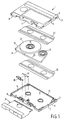
- FIG. 1 is an exploded view of a magnetic-tape cassette 1 in accordance with the invention.
- the magnetic-tape cassette 1 comprises a housing 3 having two parallel main walls 5, 7 and various transverse walls 9, 11, 13, 15.
- One of the transverse walls 9 has a magnetic-head opening 17 for the passage of a magnetic head of a magnetic-tape apparatus.
- the housing 3 accommodates two reels 19, 21 carrying a magnetic tape 23.
- a tape portion 25 of the magnetic tape extends along the magnetic-head opening 17 in the transverse wall 9.
- the reels 19, 21 carrying the magnetic tape 23 are interposed between two tape-guide foils 27, 29.
- the magnetic tape 23 has a coating side 31 where a magnetic coating is situated, and a back 33.
- the magnetic-tape cassette 1 further comprises a sliding cover 35, which is movable between a closed position, in which the sliding cover 35 covers the openings in the housing 3, and an open position, in which the sliding cover exposes the openings.
- the magnetic-tape cassette 1 further comprises a tape-pressure member 37 and a tape-guide member 39 for pressing the magnetic tape against a magnetic head and guiding the magnetic tape at the location of the magnetic head during cooperation with a magnetic-tape apparatus.
- Figure 2 illustrates the cooperation between the magnetic-tape cassette 1 and a magnetic head 41 of a magnetic-tape apparatus at the location of the magnetic-head opening 17.
- the tape portion 25 of the magnetic tape 23 near the magnetic-head opening 17 is guided by tape-guide pins 43, 45 which form part of the housing and tape guides 47, 49 which form part of the tape-pressure member 39.
- the coating side of the magnetic tape 23 is in contact with a head face 51 of the magnetic head 41 and the back 33 is in contact with a tape-pressure felt 53 of the tape-pressure member 37.
- the tape-pressure felt 53 ensures that the magnetic tape 23 is pressed against the head face 51 of the magnetic head 41 with the coating side 31 in order to guarantee a correct signal transfer between the magnetic tape and the magnetic head.
- the friction between the magnetic tape 23 and the tape-pressure felt 53 should not be too high because otherwise stick-slip effects can occur between the magnetic tape and the tape-pressure felt.
- PTFE particles are present in a contact zone where the pressure felt 53 is in contact with the magnetic tape 23.
- the contact zone is formed by a portion 55 of the pressure felt 53 which adjoins a side 57 of the tape-pressure felt 53 which faces the magnetic tape 23.
- Figure 3 shows the tape-pressure member 37 comprising a tape-pressure felt 53.
- the tape-pressure member 37 comprises a blade spring 59 having a central portion 61 to which the tape-pressure felt 53 is secured.
- the PTFE particles have been introduced into the portion 55 of the tape-pressure felt 53 adjacent the side 57 of the pressure felt 53 which is remote from the blade spring 59.
- the PTFE particles are situated on the fibres of the tape-pressure felt and should be situated at least on and near the front side 57 of the tape-pressure felt 53.
- the tape-pressure felt 53 comprises fibres of a synthetic material, for example polyamide, because the globular PTFE particles are found to adhere well thereto.
- the fibre diameter is, for example, 20 ⁇ m and the particle diameter is, for example, 15 ⁇ m.
- the PTFE particles can be applied to the fibres of the tape-pressure felt by immersing the tape-pressure felt in a liquid with a PTFE dispersion or by spraying such a liquid onto the tape-pressure felt.
- a suitable liquid for this purpose is a chlorofluorocarbon (CFC), preferably trichlorofluoroethane CCl2FCClF2, but other CFCs may also be used, such as for example trichlorofluoromethane.
- CFC chlorofluorocarbon
- the area in which the PTFE particles are present need not be limited to said portion 55 but the particles may also be present in the entire tape-pressure felt 53.
Landscapes
- Paints Or Removers (AREA)
Priority Applications (1)
| Application Number | Priority Date | Filing Date | Title |
|---|---|---|---|
| EP9393201681A EP0576065A3 (en) | 1992-06-19 | 1993-06-11 | Magnetic-tape cassette, tape-pressure member and tape-pressure felt for use in the magnetic-tape cassette, and method of manufacturing the tape-pressure felt |
Applications Claiming Priority (3)
| Application Number | Priority Date | Filing Date | Title |
|---|---|---|---|
| EP92201790 | 1992-06-19 | ||
| EP92201790 | 1992-06-19 | ||
| EP9393201681A EP0576065A3 (en) | 1992-06-19 | 1993-06-11 | Magnetic-tape cassette, tape-pressure member and tape-pressure felt for use in the magnetic-tape cassette, and method of manufacturing the tape-pressure felt |
Publications (2)
| Publication Number | Publication Date |
|---|---|
| EP0576065A2 true EP0576065A2 (fr) | 1993-12-29 |
| EP0576065A3 EP0576065A3 (en) | 1994-08-17 |
Family
ID=26131482
Family Applications (1)
| Application Number | Title | Priority Date | Filing Date |
|---|---|---|---|
| EP9393201681A Withdrawn EP0576065A3 (en) | 1992-06-19 | 1993-06-11 | Magnetic-tape cassette, tape-pressure member and tape-pressure felt for use in the magnetic-tape cassette, and method of manufacturing the tape-pressure felt |
Country Status (1)
| Country | Link |
|---|---|
| EP (1) | EP0576065A3 (fr) |
Cited By (2)
| Publication number | Priority date | Publication date | Assignee | Title |
|---|---|---|---|---|
| WO1996036967A3 (fr) * | 1995-05-17 | 1997-02-06 | Philips Electronics Nv | Cassette a bande magnetique comportant un dispositif servant a exercer une pression sur la bande, dispositif comportant une plaquette de pression et plaquette de pression pour ce dispositif |
| US6317292B1 (en) * | 1994-10-18 | 2001-11-13 | Iomega Corporation | PTFE fiber based liner for flexible high density magnetic media |
Family Cites Families (4)
| Publication number | Priority date | Publication date | Assignee | Title |
|---|---|---|---|---|
| JPS5731414Y2 (fr) * | 1978-06-20 | 1982-07-09 | ||
| JPS62245581A (ja) * | 1986-04-17 | 1987-10-26 | Fuji Photo Film Co Ltd | 磁気テ−プカセツト用パツド |
| DE9212496U1 (de) * | 1992-09-18 | 1992-11-12 | BASF Magnetics GmbH, 6800 Mannheim | Bandandruck-Körper für Magnetbandkassetten und Magnetband-Kassette damit |
| DE9301653U1 (de) * | 1993-02-06 | 1993-04-01 | BASF Magnetics (Holding) GmbH, 67059 Ludwigshafen | Andruckeinrichtung für bandförmige Aufzeichnungsträger und Kassette damit |
-
1993
- 1993-06-11 EP EP9393201681A patent/EP0576065A3/en not_active Withdrawn
Cited By (2)
| Publication number | Priority date | Publication date | Assignee | Title |
|---|---|---|---|---|
| US6317292B1 (en) * | 1994-10-18 | 2001-11-13 | Iomega Corporation | PTFE fiber based liner for flexible high density magnetic media |
| WO1996036967A3 (fr) * | 1995-05-17 | 1997-02-06 | Philips Electronics Nv | Cassette a bande magnetique comportant un dispositif servant a exercer une pression sur la bande, dispositif comportant une plaquette de pression et plaquette de pression pour ce dispositif |
Also Published As
| Publication number | Publication date |
|---|---|
| EP0576065A3 (en) | 1994-08-17 |
Similar Documents
| Publication | Publication Date | Title |
|---|---|---|
| US3761994A (en) | Magnetic tape head cleaning apparatus | |
| US4888657A (en) | Contoured head assembly for use in a cassette loaded recorder | |
| US4417704A (en) | Magnetic recording tape cassette | |
| EP0576065A2 (fr) | Cassette à bande magnétique, élément presse-bande et feutre presse-bande convenant pour être utilisés dans cette cassette et procédé de fabrication du feutre presse-bande | |
| US4766511A (en) | Anti-static surface for magnetic tape cartridge | |
| US4796135A (en) | Two layered tape pad for a magnetic tape cassette | |
| CN100442358C (zh) | 引导带及其制造方法和磁带盒式磁盘 | |
| EP0397713B1 (fr) | Assemblage de tete profile utilise dans un enregistreur a cassette | |
| EP0373179B1 (fr) | Ensemble de tete magnetique en ligne utilise dans un enregistreur charge d'une cassette | |
| US5528438A (en) | Drum assembly having a lower fixed drum and an upper rotary drum with a particularly shaped outer surface | |
| US4720413A (en) | Magnetic recording medium having a back coat layer | |
| JPH0216464Y2 (fr) | ||
| US5355271A (en) | Tape cassette with resiliently mounted tape cleaner | |
| EP0615238B1 (fr) | Appareil pour l'enregistrement et la lecture de support d'enregistrement en forme de bande | |
| JPH0660600A (ja) | 磁気テープ・カセット、それに用いるテープ押圧部材とテープ押圧フェルト、及びテープ押圧フェルトの製造方法 | |
| US5808829A (en) | Loading device for draining static electricity of a cassette of a VCR | |
| KR950000452Y1 (ko) | 자기 테이프 카세트용 슬랙리미터 | |
| Osaki | Tribology of videotapes | |
| EP0443426B1 (fr) | Mécanisme de guidage de bande pour un dispositif d'enregistrement et de reproduction | |
| JPS59227026A (ja) | 磁気記録媒体 | |
| JP3438075B2 (ja) | 磁気テ−プおよびこの磁気テ−プを巻回した磁気テ−プ巻回体並びにこの磁気テ−プ巻回体を装着した磁気テ−プカ−トリッジ | |
| CA1158359A (fr) | Enregistreur magnetique multivitesse a tete de lecture resistante a l'usure | |
| JPS6023827Y2 (ja) | テ−プパツド装置 | |
| JPS6235180Y2 (fr) | ||
| KR940004326Y1 (ko) | 자기기록 재생기기의 테이프 장력조절 장치 |
Legal Events
| Date | Code | Title | Description |
|---|---|---|---|
| PUAI | Public reference made under article 153(3) epc to a published international application that has entered the european phase |
Free format text: ORIGINAL CODE: 0009012 |
|
| AK | Designated contracting states |
Kind code of ref document: A2 Designated state(s): AT BE CH DE DK ES FR GB GR IT LI LU MC NL PT SE |
|
| PUAL | Search report despatched |
Free format text: ORIGINAL CODE: 0009013 |
|
| AK | Designated contracting states |
Kind code of ref document: A3 Designated state(s): AT BE CH DE DK ES FR GB GR IT LI LU MC NL PT SE |
|
| RAP1 | Party data changed (applicant data changed or rights of an application transferred) |
Owner name: N.V. PHILIPS' GLOEILAMPENFABRIEKEN |
|
| STAA | Information on the status of an ep patent application or granted ep patent |
Free format text: STATUS: THE APPLICATION IS DEEMED TO BE WITHDRAWN |
|
| 18D | Application deemed to be withdrawn |
Effective date: 19950218 |