EP0576083A2 - Appareil à bande magnétique comprenant un dispositif à galet presseur - Google Patents
Appareil à bande magnétique comprenant un dispositif à galet presseur Download PDFInfo
- Publication number
- EP0576083A2 EP0576083A2 EP93201755A EP93201755A EP0576083A2 EP 0576083 A2 EP0576083 A2 EP 0576083A2 EP 93201755 A EP93201755 A EP 93201755A EP 93201755 A EP93201755 A EP 93201755A EP 0576083 A2 EP0576083 A2 EP 0576083A2
- Authority
- EP
- European Patent Office
- Prior art keywords
- pressure
- roller
- pressure roller
- bearing member
- bearing
- Prior art date
- Legal status (The legal status is an assumption and is not a legal conclusion. Google has not performed a legal analysis and makes no representation as to the accuracy of the status listed.)
- Granted
Links
Images
Classifications
-
- G—PHYSICS
- G11—INFORMATION STORAGE
- G11B—INFORMATION STORAGE BASED ON RELATIVE MOVEMENT BETWEEN RECORD CARRIER AND TRANSDUCER
- G11B15/00—Driving, starting or stopping record carriers of filamentary or web form; Driving both such record carriers and heads; Guiding such record carriers or containers therefor; Control thereof; Control of operating function
- G11B15/18—Driving; Starting; Stopping; Arrangements for control or regulation thereof
- G11B15/26—Driving record carriers by members acting directly or indirectly thereon
- G11B15/28—Driving record carriers by members acting directly or indirectly thereon through rollers driving by frictional contact with the record carrier, e.g. capstan; Multiple arrangements of capstans or drums coupled to means for controlling the speed of the drive; Multiple capstan systems alternately engageable with record carrier to provide reversal
- G11B15/29—Driving record carriers by members acting directly or indirectly thereon through rollers driving by frictional contact with the record carrier, e.g. capstan; Multiple arrangements of capstans or drums coupled to means for controlling the speed of the drive; Multiple capstan systems alternately engageable with record carrier to provide reversal through pinch-rollers or tape rolls
Definitions
- the invention relates to a magnetic-tape apparatus comprising a rotatably drivable capstan for driving the magnetic tape and comprising a pressure-roller device which comprises a pressure roller to be pressed against the capstan, a movable pressure-roller support, a pressure-roller spindle carried by the pressure-roller support, and a substantially rotationally symmetrical bearing member arranged on the pressure-roller spindle for rotatably supporting the pressure-roller spindle, an inner bearing surface being associated with the pressure roller and the bearing member having an outer bearing surface adapted to cooperate with the inner bearing surface, and the inner bearing surface associated with the pressure roller and the outer bearing surface of the bearing member each having a curved shape allowing the pressure roller to perform a pivotal movement to adapt the axial direction of the pressure roller to the axial direction of the capstan.
- Such an apparatus of the type defined in the opening paragraph is known from, for example, DE-GM 1,793,121.
- the inner bearing surface associated with the pressure roller and the outer bearing surface of the bearing member both have a substantially spherical shape.
- the inner bearing surface associated with the pressure roller is formed by a first bearing-surface part provided on an annular portion of the pressure roller and by a second bearing-surface part provided on a dome-shaped insert, a pressure spring acting upon the insert to press the insert against the bearing member mounted on the pressure-roller spindle, i.e. against the outer bearing surface of this bearing member.
- the invention is characterised in that the inner bearing surface associated with the pressure roller is formed by an inner toric surface having a given meridian radius and the outer bearing surface of the bearing member is formed by an outer toric surface having a given meridian radius, and the outer toric surface of the bearing member engages with clearance in the inner toric surface associated with the pressure roller.
- the pivotal centre about which the pressure roller is pivoted is in fact formed by the contact zone between the two toric bearing surfaces, which zone is situated adjacent the capstan, comparatively close to the contact surface of the capstan, as a result of which substantially no asymmetries occur in the force distribution between the capstan and the pressure roller and the magnetic tape is not subjected to any undesirable load, thus always assuring a correct tape transport.
- the pressure-roller spindle and the bearing member mounted on it may form a single part and the pressure roller may comprise two parts, the pressure roller being mounted on the bearing member in that first of all one part of the pressure roller is mounted, after which the second part of the pressure roller is fitted and connected to the first part of the pressure roller.
- the bearing member is rotatably mounted on the pressure-roller spindle and surrounds the pressure-roller spindle with an inner hollow-cylindrical circumferential surface, and the bearing member further comprises substantially radial slots which in the circumferential direction alternately terminate in its outer circumferential surface comprising the outer toric surface and in its inner circumferential surface surrounding the pressure-roller spindle, of which each time two circumferentially adjacent slots overlap one another in the radial direction.
- the outer toric surface of the bearing member and the inner toric surface of the pressure roller have the same meridian radius. This is advantageous in order to achieve a very reliable and stable adaptation of the axial direction of the pressure roller to the axial direction of the capstan upon any deviation of the pressure roller from its parallel position relative to the capstan which may occur in practice.
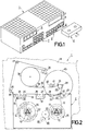
- Fig. 1 is a reduced-scale diagrammatic oblique view of a recording and reproducing apparatus for television signals and audio signals, which apparatus is constructed to receive a cassette accommodating a magnetisable record carrier in the form of a tape which extends between two juxtaposed reel hubs and on/from which television signals can recorded or reproduced in inclined tracks by means of rotatable magnetic heads.
- Fig. 2 shows diagrammatically a part of the apparatus of Fig. 1 to an enlarged scale in comparison with Fig. 1, a cassette being loaded into the apparatus and the record carrier being withdrawn from the cassette and wrapped around guiding and scanning elements of the apparatus.
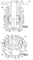
- Fig. 3 shows a pressure-roller device of the apparatus in Figs. 1 and 2 to a scale larger than full scale in a cross-sectional view of the pressure roller of this pressure-roller device, which pressure roller is mounted so as to be rotatable about and pivotable relative to a pressure-roller spindle by means of a bearing member.
- Fig. 4 shows the bearing member of the pressure-roller device in Fig. 3 in an oblique view to an enlarged scale in comparison with Fig. 3.
- Fig. 1 shows a recording and reproducing apparatus 1 constructed for recording and reproducing television signals and audio signals on a magnetisable record carrier in the form of a tape, hereinafter briefly referred to as a magnetic tape.
- a magnetic tape is accommodated in a cassette 2 which is shown diagrammatically in Fig. 1 and which comprises two juxtaposed reel hubs between which the magnetic tape extends along a path defined by means of tape guides of the cassette.
- the cassette 2 can be inserted by hand into the apparatus 1 in a direction indicated by an arrow 5 through an opening 4 which can be closed by means of a cover 3 which can be moved inward.
- the apparatus 1 When the cassette 2 is loaded into the apparatus 1 it is inserted into a movable cassette holder which upon complete insertion of the cassette into the apparatus lowers the cassette perpendicularly to the cassette main walls into an operating position, shown diagrammatically in Fig. 2, inside the apparatus.
- the apparatus 1 For starting the modes of the apparatus, such as “record”, “normal forward play”, “still reproduction”, “normal reverse play”, “fast forward”, “fast reverse” and the like the apparatus 1 comprises a first set 6 of controls.
- the apparatus 1 For programming the apparatus and for entering further data, for example to set a daytime clock, the apparatus 1 comprises a second set 7 of controls.
- the apparatus 1 comprises two display devices 8 and 9, whose displays each comprise for example seven segments and which serve for example for indicating the count of a tape-length measurement counter and for displaying the daytime.
- a cassette 2 inserted into the apparatus 1 is lowered into an operating position in the apparatus.
- the cassette 2 accommodates two juxtaposed rotatably drivable reel hubs 10 and 11 between which the magnetic tape 12 extends inside the cassette 2 along a path represented partly as a dash-dot line 13 and on which the magnetic tape can be wound in accordance with its instantaneous direction of transport and in opposite winding directions, as is indicated by means of the arrows 14 and 15.
- two reel spindles 16 and 17 enter into driving engagement with the reel hubs 10 and 11 in the cassette 2, which spindles are rotatably supported in a deck plate 18 of the apparatus 1.
- the reel spindles 16 and 17 can rotatably drive the two reel hubs 10 and 11 which coaxially engage with these spindles.
- the reel spindles 16 and 17 may be of another construction than shown and may, for example, each comprise a centred positioning mandrel for positioning a reel hub and, eccentric thereto, a driving mandrel for driving a reel hub.
- a drive arrangement 19 which is shown only diagrammatically in Fig.
- a drive wheel 20 which can be motor driven and which stationarily arranged in the apparatus 1, and a drive wheel 21, which can be driven by the first-mentioned wheel and which is supported to be movable parallel to the deck plate 18, which drive wheel 21 can be brought selectively into driving engagement with the circumference of one of two reel-spindle wheels 22 and 23 which are coaxial with and rotationally locked to the reel spindles 16 and 17 and which are disposed at the same axial level.
- a cassette shutter not shown and arranged at its front 24, is opened to expose a cassette opening in the front 24, through which opening the magnetic tape 12 accommodated in the cassette 2 can be extracted, and four tape guides 25, 26, 27, 28 and a pressure roller 29, which are each in a rest position shown in dash-dot lines in Fig. 2, engage three openings 30, 31 and 32 in the cassette 2, engaging behind the magnetic tape 12 at the location indicated by the dash-dot line 13.
- the tape guides 25, 26, 27 and 28 can move into their operating positions shown in solid lines in Fig. 2, the pressure roller 29 being also movable into an intermediate position, not shown in Fig.
- the path of the magnetic tape 12 will be as indicated by a solid line.
- the magnetic tape then extends from the reel hub 10 to the reel hub 11 via two tape guides 34 and 35 provided in the cassette 2, a tape-tension sensor pin 36, which forms part of a tape-tension control unit, not shown, the movable tape guides 25, 27 and 27, a stationary magnetic head 37 for erasing all the signals recorded on the magnetic tape 12, a drum-shaped scanning unit 38 comprising rotary magnetic heads for recording and reproducing television signals in/from contiguous video tracks which are inclined relative to the longitudinal direction of the magnetic tape, a stationary tape guide 39, a stationary magnetic head 40 for erasing audio signals recorded in an audio track extending in the longitudinal direction of the magnetic tape 12, a further stationary magnetic head 41 for recording and reproducing audio signals in the audio track and for recording and reproducing synchronisation signals in/from a synchronisation track extending in the longitudinal direction of the magnetic tape and parallel to the audio track, the capstan 33
- the capstan 33 which is connected to the flywheel 45 in the customary manner, can be driven selectively in one of the two directions of rotation with a constant speed.
- the pressure roller 29 is pressed against the capstan 33 this enables the magnetic tape 12 to be driven selectively in one of two opposite transport directions with a constant speed of transport.
- the magnetic tape 12 is driven in a direction opposite to that indicated by the arrow 46, which corresponds to the so-called “normal reverse operation”, also referred to as “reverse operation”, in which in the "normal reverse play” mode recorded television signals are reproduced so as to obtain reverse motion scenes and in which the reel-spindle wheel 22, which is rotationally locked to the reel spindle 16, is driven by the drive wheel 21 of the drive arrangement 19 to wind the magnetic tape 12 onto the reel hub 10 in the direction indicated by the arrow 14.
- the apparatus can also be set to the "fast forward” and “fast reverse” modes in which the magnetic tape 12 is wound between the reel hubs 10 and 11 with a higher speed of transport.
- the magnetic tape 12 is returned into the cassette 2 before such a winding operation by resetting the movable tape guides 25, 26, 27, 28 and the pressure roller 29 from their operating positions into rest positions shown in dash-dot lines in Fig. 2 and by simultaneously driving the reel spindle 16 in the direction indicated by the arrow 14 by means of the drive wheel 21 of the drive arrangement 19, after which the magnetic tape 12 again extends along the path indicated by the dash-dot line 13.
- the magnetic tape 12 When the magnetic tape 12 is wound in the "fast forward” and the “fast reverse” mode the magnetic tape 12 is driven exclusively by driving one of the two reel hubs 10 and 11, in which two modes the two reel spindles 16 and 17 can again be driven by the drive arrangement 19 whose drive wheel 21 is brought into circumferential driving engagement with the reel-spindle wheel 23 in the "fast forward” mode and with the reel-spindle wheel 22 in the "fast reverse” mode.
- the pressure roller 29 does not cooperate with the magnetic tape 12 during fast winding.
- the magnetic tape 12 is pressed against the capstan 33 by means of the pressure roller 29.
- the circumference of the pressure roller 29 is exactly positioned against the capstan 33, the magnetic tape 12 being interposed between the pressure roller 29 and the capstan 33 at the location of a part of the pressure roller 29.
- an exact positioning of the pressure roller 29 against the capstan 33 is to be understood to mean that the axis of the pressure roller 29 extends exactly parallel to the axis of the capstan 33.
- the pressure roller 29 is supported so as to be pivotable, as will be described in detail with reference to Fig. 3.
- a pressure-roller device 47 of the apparatus 1 is shown in Fig. 3, the pressure roller 29 forming part of this device.
- the pressure-roller device 47 comprises a lever-type pressure-roller support 48 which, in a manner not shown, is movable relative to a deck plate 18, not shown in Fig. 3, and which is integrally connected to a bearing sleeve 49.
- a steel pressure-roller spindle 50 is pressed into the bearing sleeve 49.
- the pressure-roller spindle 50 carries a substantially rotationally symmetrical plastics bearing member 51 for rotatably supporting the pressure roller 29, the bearing member 51 surrounding the pressure-roller spindle 50 with an inner circumferential surface 52.
- the bearing member 51 whose construction is apparent from Fig. 4, comprises an substantially cylindrical inner part 53, from whose outer circumferential surface a toric part 54 projects, and has an outer bearing surface 56 adapted to cooperate with an inner bearing surface 55 associated with the pressure roller 29.
- the outer bearing surface 56 of the bearing member 51 and the inner bearing surface 55 associated with the pressure roller 29 each have a curved shape allowing the pressure roller 29 to perform a pivotal movement to adapt the axial direction of the pressure roller 29 to the axial direction of the capstan 33.
- the pressure roller 29 of the pressure-roller device 47 comprises a sleeve 58 made of a metal, for example steel or aluminium, in whose inner side the inner bearing surface 55 has been formed.
- a sealing disc 60 is fitted into a groove 59 formed in the end portion of the sleeve 58 which is remote from the pressure-roller support 48.
- the outer circumferential surface 61 of the sleeve 58 is provided with a sheath 62 of rubber or an elastomeric material, adapted to cooperate with the capstan 33.
- the outer bearing surface 56 of the bearing member 51 is advantageously formed by a outer toric surface of the toric part 54, which toric surface has a given meridian radius, and the inner bearing surface 55 associated with the pressure roller 29 is formed by an inner toric surface having a given meridian radius.
- the outer toric surface 56 and the inner toric surface 55 have the same meridian radius. It is then essential that the outer toric surface 56 of the bearing member 51 and the inner toric surface 55 associated with the pressure roller 29 interengage with clearance.
- the bearing member 51 further comprises substantially radial slots 64 and 65 which in the circumferential direction alternately terminate in its outer circumferential surface 63 comprising the outer toric surface 56 and in its inner circumferential surface 52 surrounding the pressure-roller spindle 50, of which each time two circumferentially adjacent slots overlap one another in the radial direction.
- the nominal meridian radius of the inner toric surface 55 on the pressure roller 29 and of the outer toric surface 56 on the bearing member 51 was selected to be 3.0 mm, the nominal diameter of the bearing member 51 at the location of its outer toric surface 56 to be 8.7 mm, and the nominal inner diameter of the pressure roller 29 at the location of its inner toric surface 55 to be 9.0 mm, so that the clearance between the inner toric surface 55 and the outer toric surface 56 had a nominal value of 0.3 mm.
- the pressure-roller spindle 47 is first pressed into the pressure-roller support 48. Subsequently, the bearing member 51 is inserted into the pressure roller 29 in the axial direction, the bearing member 51 first being compressed elastically in the circumferential direction and then snapping with its outer toric surface 56 into the pressure roller 29 at the location of the inner toric surface 55. Now the bearing member 51 together with the pressure roller 29 is slid onto the pressure-roller spindle 50, after which the bearing member 51 is no longer circumferentially compressible. Subsequently, the retaining ring 57 is pressed onto pressure-roller spindle 50 to position and retain the bearing member 51 in the axial direction.
- Fig. 3 shows the pressure-roller device 47 in a situation in which the pressure roller 29 occupies a neutral centre position.
- the pressure roller 29 is pressed against the capstan 33, the outer toric surface 56 of the bearing member 51 being pressed against the inner toric surface 55 of the pressure roller 29 in a substantially linear contact zone at the location radially opposite the capstan 33.
- This contact zone forms the pivotal centre about which the pressure roller 29 can be pivoted owing to the clearance between the outer toric surface 56 of the bearing member 51 and the inner toric surface 55 of the pressure roller 29 in order to adapt the axial direction of the pressure roller 29 to the axial direction of the capstan 33.
- the two meridian radii may also differ slightly, in which case it is found to be favourable for a high positional stability if on a micrometre scale the inner toric surface 55 of the pressure roller 29 has a meridian radius smaller than that of the outer toric surface 56 of the bearing member 51.
- the high positional stability is enhanced by the flexing effects in the rubber sheath 62 of the pressure roller 29 during its cooperation with the capstan 33.
- the bearing member may be of another construction and may not have mutually overlapping radial slots.
- the bearing member may be integral with the pressure-roller spindle, which may then be wholly made of a plastics.
- the pressure-roller device may comprise a pressure-roller support of another construction.
- the invention may be employed in differently constructed magnetic-tape apparatuses.
Landscapes
- Registering, Tensioning, Guiding Webs, And Rollers Therefor (AREA)
- Rolls And Other Rotary Bodies (AREA)
- Manufacturing Of Magnetic Record Carriers (AREA)
Applications Claiming Priority (2)
| Application Number | Priority Date | Filing Date | Title |
|---|---|---|---|
| AT1307/92 | 1992-06-26 | ||
| AT0130792A AT397734B (de) | 1992-06-26 | 1992-06-26 | Magnetbandgerät mit einer andruckrolleneinrichtung |
Publications (3)
| Publication Number | Publication Date |
|---|---|
| EP0576083A2 true EP0576083A2 (fr) | 1993-12-29 |
| EP0576083A3 EP0576083A3 (en) | 1994-07-20 |
| EP0576083B1 EP0576083B1 (fr) | 1998-09-02 |
Family
ID=3511058
Family Applications (1)
| Application Number | Title | Priority Date | Filing Date |
|---|---|---|---|
| EP93201755A Expired - Lifetime EP0576083B1 (fr) | 1992-06-26 | 1993-06-18 | Appareil à bande magnétique comprenant un dispositif à galet presseur |
Country Status (7)
| Country | Link |
|---|---|
| US (1) | US5452833A (fr) |
| EP (1) | EP0576083B1 (fr) |
| JP (1) | JPH0619136U (fr) |
| AT (1) | AT397734B (fr) |
| DE (1) | DE69320710T2 (fr) |
| MY (1) | MY131498A (fr) |
| SG (1) | SG49216A1 (fr) |
Cited By (2)
| Publication number | Priority date | Publication date | Assignee | Title |
|---|---|---|---|---|
| EP0896330A3 (fr) * | 1997-08-06 | 1999-03-03 | Mitsubishi Denki Kabushiki Kaisha | Mécanisme de support pour unité à galet presseur pour l' utilisation dans un appareil d'enregistrement / reproduction magnétique |
| CN107008660A (zh) * | 2017-05-19 | 2017-08-04 | 四川德恩精工科技股份有限公司 | 利用机器人单轴手臂测皮带长度的装置及筛选皮带的方法 |
Families Citing this family (8)
| Publication number | Priority date | Publication date | Assignee | Title |
|---|---|---|---|---|
| US5803335A (en) * | 1995-04-18 | 1998-09-08 | Daewoo Electronics Co., Ltd. | Pinch roller assembly having a rubber cushion for making a contact surface thereof pivotable |
| US5727753A (en) * | 1995-12-05 | 1998-03-17 | The Servants, Inc. | Web tension equalizer roll |
| KR970046073U (ko) * | 1995-12-13 | 1997-07-31 | 브이씨알장치의 핀치로울러 | |
| JP2968225B2 (ja) * | 1997-02-12 | 1999-10-25 | ヤマウチ株式会社 | ピンチローラー及びピンチローラー装置 |
| CN1191582C (zh) * | 1999-07-22 | 2005-03-02 | 株式会社明治橡胶化成 | 压轮设备 |
| US6481894B1 (en) | 2001-02-23 | 2002-11-19 | Lord Corporation | Pitch bearing |
| CN1457490A (zh) | 2001-03-06 | 2003-11-19 | 皇家菲利浦电子有限公司 | 具有压力辊装置和压力辊单元的磁带装置 |
| JP2002352488A (ja) * | 2001-05-25 | 2002-12-06 | Matsushita Electric Ind Co Ltd | ピンチローラ装置 |
Family Cites Families (15)
| Publication number | Priority date | Publication date | Assignee | Title |
|---|---|---|---|---|
| US1767371A (en) * | 1925-12-03 | 1930-06-24 | Free Sewing Machine Company | Drive-chain tension adjuster |
| US3315859A (en) * | 1965-03-31 | 1967-04-25 | Eastman Kodak Co | Web tracking mechanism |
| US3662937A (en) * | 1970-03-06 | 1972-05-16 | Minnesota Mining & Mfg | Magnetic tape pressure roller |
| JPS5068503A (fr) * | 1973-10-23 | 1975-06-07 | ||
| US3989320A (en) * | 1975-04-07 | 1976-11-02 | Heim Universal Corporation | Self-aligning bearing with preloading braking member |
| IT1105783B (it) * | 1978-08-23 | 1985-11-04 | Werbetronic Ag | Perfezionamento nei rulli pressori per registratori a nastro |
| US4403720A (en) * | 1982-02-05 | 1983-09-13 | Bell & Howell Company | Bidirectional tape advancing method and apparatus |
| JPS59207048A (ja) * | 1983-05-09 | 1984-11-24 | Mitsubishi Electric Corp | ピンチロ−ラの自動調芯機構 |
| US4591275A (en) * | 1984-06-15 | 1986-05-27 | Interlake, Inc. | Apparatus for mixing pulverulent material on a conveyor belt |
| JPH056416Y2 (fr) * | 1987-03-19 | 1993-02-18 | ||
| GB2197933B (en) * | 1986-09-30 | 1990-08-29 | Shigeo Takahashi | Roller structure |
| JP2591062B2 (ja) * | 1988-05-13 | 1997-03-19 | 松下電器産業株式会社 | ピンチローラ装置 |
| JPH01307950A (ja) * | 1988-06-07 | 1989-12-12 | Matsushita Electric Ind Co Ltd | ピンチローラ装置 |
| AT393331B (de) * | 1989-10-17 | 1991-09-25 | Philips Nv | Andruckrollenanordnung |
| JPH0464950A (ja) * | 1990-07-04 | 1992-02-28 | Matsushita Electric Ind Co Ltd | ピンチローラ装置 |
-
1992
- 1992-06-26 AT AT0130792A patent/AT397734B/de not_active IP Right Cessation
-
1993
- 1993-06-09 MY MYPI93001112A patent/MY131498A/en unknown
- 1993-06-18 EP EP93201755A patent/EP0576083B1/fr not_active Expired - Lifetime
- 1993-06-18 SG SG1996007697A patent/SG49216A1/en unknown
- 1993-06-18 DE DE69320710T patent/DE69320710T2/de not_active Expired - Fee Related
- 1993-06-28 JP JP034986U patent/JPH0619136U/ja active Pending
-
1994
- 1994-05-10 US US08/240,950 patent/US5452833A/en not_active Expired - Fee Related
Cited By (4)
| Publication number | Priority date | Publication date | Assignee | Title |
|---|---|---|---|---|
| EP0896330A3 (fr) * | 1997-08-06 | 1999-03-03 | Mitsubishi Denki Kabushiki Kaisha | Mécanisme de support pour unité à galet presseur pour l' utilisation dans un appareil d'enregistrement / reproduction magnétique |
| US6149044A (en) * | 1997-08-06 | 2000-11-21 | Mitsubishi Denki Kabushiki Kaisha | Supporting mechanism for pinch roller unit for use in magnetic recording/reproducing apparatus |
| CN107008660A (zh) * | 2017-05-19 | 2017-08-04 | 四川德恩精工科技股份有限公司 | 利用机器人单轴手臂测皮带长度的装置及筛选皮带的方法 |
| CN107008660B (zh) * | 2017-05-19 | 2023-05-30 | 四川德恩精工科技股份有限公司 | 利用机器人单轴手臂测皮带长度的装置及筛选皮带的方法 |
Also Published As
| Publication number | Publication date |
|---|---|
| ATA130792A (de) | 1993-10-15 |
| AT397734B (de) | 1994-06-27 |
| EP0576083B1 (fr) | 1998-09-02 |
| JPH0619136U (ja) | 1994-03-11 |
| DE69320710T2 (de) | 1999-03-25 |
| US5452833A (en) | 1995-09-26 |
| EP0576083A3 (en) | 1994-07-20 |
| DE69320710D1 (de) | 1998-10-08 |
| MY131498A (en) | 2007-08-30 |
| SG49216A1 (en) | 1998-05-18 |
Similar Documents
| Publication | Publication Date | Title |
|---|---|---|
| US3995317A (en) | Helical scan apparatus for video tape or the like and having rotating-head inclination-adjustment means | |
| US4309002A (en) | Mechanism for preventing loosening of magnetic recording tape of tape cassette | |
| EP0576083B1 (fr) | Appareil à bande magnétique comprenant un dispositif à galet presseur | |
| US5365386A (en) | Loading post driving device | |
| US3678213A (en) | Magnetic recording and/or reproducing system having guide pins mounted on independently rotating plates for withdrawing tape from cassette | |
| US6745968B1 (en) | Single-reel cartridge for data processing having a multi-part braking system | |
| US4603359A (en) | Rotary head device | |
| US4012787A (en) | Video tape recorder | |
| US5239432A (en) | Magnetic tape cassette having a slot for inserting a recording and/or reproducing head therethrough and a magnetic tape recording and/or reproducing apparatus for use with such magnetic tape cassette | |
| JP2003168278A (ja) | 磁気記録テープ巻き取り用リールおよび磁気記録テープドライブ | |
| CN1180416C (zh) | 包括至少一个具有至少一个阻尼凸起的引导装置的记录和/或再现设备 | |
| EP0228904B1 (fr) | Cassettes à bande magnétique | |
| US5227934A (en) | Device for making independently operable in time, a tape recording device and a device for playing back said tape | |
| US5341257A (en) | Head cleaning device for magnetic tape cassette apparatus having a rotating head | |
| US3863853A (en) | Endless magnetic tape cartridge | |
| GB2302981A (en) | Magnetic tape apparatus for eliminating slack when changing winding direction | |
| US4701821A (en) | Helical scan tape recorder without head-tape contact in stand-by mode | |
| KR200154793Y1 (ko) | 가압롤러 부재를 구비한 자기 테이프 장치 | |
| RU1838832C (ru) | Записывающее и/или воспроизвод щее устройство дл ленточного носител информации | |
| US20020048122A1 (en) | Head sending mechanism, backlash eliminating mechanism therefor and actuator assembly | |
| US5803336A (en) | Pinch roller type tape drive assembly | |
| US4071863A (en) | Stationary magnetic tape transducing system with means for controlling the air bearing support | |
| US5044574A (en) | Reel hub latch assembly | |
| EP0718836B1 (fr) | Appareil d'enregistrement/réproduction magnétique avec mécanisme de positionnement pour le tambour de guidage de la bande | |
| US5383074A (en) | Auto-reverse magnetic-head unit having a flexible conductor board |
Legal Events
| Date | Code | Title | Description |
|---|---|---|---|
| PUAI | Public reference made under article 153(3) epc to a published international application that has entered the european phase |
Free format text: ORIGINAL CODE: 0009012 |
|
| AK | Designated contracting states |
Kind code of ref document: A2 Designated state(s): DE FR GB |
|
| PUAL | Search report despatched |
Free format text: ORIGINAL CODE: 0009013 |
|
| AK | Designated contracting states |
Kind code of ref document: A3 Designated state(s): DE FR GB |
|
| RAP1 | Party data changed (applicant data changed or rights of an application transferred) |
Owner name: N.V. PHILIPS' GLOEILAMPENFABRIEKEN |
|
| 17P | Request for examination filed |
Effective date: 19950120 |
|
| 17Q | First examination report despatched |
Effective date: 19961014 |
|
| GRAG | Despatch of communication of intention to grant |
Free format text: ORIGINAL CODE: EPIDOS AGRA |
|
| GRAG | Despatch of communication of intention to grant |
Free format text: ORIGINAL CODE: EPIDOS AGRA |
|
| GRAH | Despatch of communication of intention to grant a patent |
Free format text: ORIGINAL CODE: EPIDOS IGRA |
|
| GRAH | Despatch of communication of intention to grant a patent |
Free format text: ORIGINAL CODE: EPIDOS IGRA |
|
| GRAA | (expected) grant |
Free format text: ORIGINAL CODE: 0009210 |
|
| RAP3 | Party data changed (applicant data changed or rights of an application transferred) |
Owner name: KONINKLIJKE PHILIPS ELECTRONICS N.V. |
|
| AK | Designated contracting states |
Kind code of ref document: B1 Designated state(s): DE FR GB |
|
| REF | Corresponds to: |
Ref document number: 69320710 Country of ref document: DE Date of ref document: 19981008 |
|
| ET | Fr: translation filed | ||
| PLBE | No opposition filed within time limit |
Free format text: ORIGINAL CODE: 0009261 |
|
| STAA | Information on the status of an ep patent application or granted ep patent |
Free format text: STATUS: NO OPPOSITION FILED WITHIN TIME LIMIT |
|
| 26N | No opposition filed | ||
| PGFP | Annual fee paid to national office [announced via postgrant information from national office to epo] |
Ref country code: FR Payment date: 20010625 Year of fee payment: 9 |
|
| PGFP | Annual fee paid to national office [announced via postgrant information from national office to epo] |
Ref country code: GB Payment date: 20010629 Year of fee payment: 9 |
|
| PGFP | Annual fee paid to national office [announced via postgrant information from national office to epo] |
Ref country code: DE Payment date: 20010821 Year of fee payment: 9 |
|
| REG | Reference to a national code |
Ref country code: GB Ref legal event code: IF02 |
|
| PG25 | Lapsed in a contracting state [announced via postgrant information from national office to epo] |
Ref country code: GB Free format text: LAPSE BECAUSE OF NON-PAYMENT OF DUE FEES Effective date: 20020618 |
|
| PG25 | Lapsed in a contracting state [announced via postgrant information from national office to epo] |
Ref country code: DE Free format text: LAPSE BECAUSE OF NON-PAYMENT OF DUE FEES Effective date: 20030101 |
|
| GBPC | Gb: european patent ceased through non-payment of renewal fee |
Effective date: 20020618 |
|
| PG25 | Lapsed in a contracting state [announced via postgrant information from national office to epo] |
Ref country code: FR Free format text: LAPSE BECAUSE OF NON-PAYMENT OF DUE FEES Effective date: 20030228 |
|
| REG | Reference to a national code |
Ref country code: FR Ref legal event code: ST |