EP0576145B1 - Kochvorrichtung mit Gassmesswertgeber - Google Patents
Kochvorrichtung mit Gassmesswertgeber Download PDFInfo
- Publication number
- EP0576145B1 EP0576145B1 EP93304016A EP93304016A EP0576145B1 EP 0576145 B1 EP0576145 B1 EP 0576145B1 EP 93304016 A EP93304016 A EP 93304016A EP 93304016 A EP93304016 A EP 93304016A EP 0576145 B1 EP0576145 B1 EP 0576145B1
- Authority
- EP
- European Patent Office
- Prior art keywords
- cooking
- temperature
- cabinet
- bread
- period
- Prior art date
- Legal status (The legal status is an assumption and is not a legal conclusion. Google has not performed a legal analysis and makes no representation as to the accuracy of the status listed.)
- Expired - Lifetime
Links
- 238000010411 cooking Methods 0.000 title claims description 91
- 235000008429 bread Nutrition 0.000 claims description 84
- 238000010438 heat treatment Methods 0.000 claims description 19
- 235000013305 food Nutrition 0.000 claims description 16
- 238000000034 method Methods 0.000 claims description 7
- 230000007423 decrease Effects 0.000 claims description 4
- 238000004519 manufacturing process Methods 0.000 claims description 3
- 238000010586 diagram Methods 0.000 description 2
- 238000002474 experimental method Methods 0.000 description 2
- 238000012986 modification Methods 0.000 description 2
- 230000004048 modification Effects 0.000 description 2
- 238000005259 measurement Methods 0.000 description 1
Images




Classifications
-
- F—MECHANICAL ENGINEERING; LIGHTING; HEATING; WEAPONS; BLASTING
- F24—HEATING; RANGES; VENTILATING
- F24C—DOMESTIC STOVES OR RANGES ; DETAILS OF DOMESTIC STOVES OR RANGES, OF GENERAL APPLICATION
- F24C7/00—Stoves or ranges heated by electric energy
- F24C7/08—Arrangement or mounting of control or safety devices
- F24C7/087—Arrangement or mounting of control or safety devices of electric circuits regulating heat
Definitions
- the present invention relates to a automatic cooking appliance which includes a "toast" function.
- a gas sensor detects gas generated by bread being toasted.
- a controller can determine the amount of gas driven off from the bread during a predetermined period of time after toasting begins. From this measurement, it can determine whether bread being toasted was initially frozen or at room temperature. Based on this determination, heating can be adjusted to properly toast the bread regardless of its initial state.
- a gas sensor for measuring the amount of moisture driven off from bread being toasted in order to determine whether the bread was initially at room temperature or was frozen.
- the cooking appliance automatically toasts the bread for a time appropriate to the so determined state of the bread.
- a microprocessor based controller can discriminate the initial condition or state of the bread, i.e., whether it was initially frozen or at room temperature. If the bread were determined to be initially frozen, the cooking appliance would adjust its toasting program to properly toast the initially frozen bread. For example, heat could be applied for a longer time, the temperature could be raised, etc. Thus, regardless of whether the bread was initially frozen or not, it would be properly toasted.
- Such appliances operate satisfactorily when they are operated intermittently. However, when such appliances are operated continuously, i.e., to toast one piece of bread after another, the toasting function is not properly adjusted. The problem exists because of residual heat remaining in the cooking cabinet after toasting. As the appliance is used more and more, this residual heat builds up even more. When a slice of bread is put into the cooking cabinet, even though the bread may be frozen, much moisture is driven from it. The cooking appliance is unable to properly discriminate between normal bread and frozen bread. All breads, whether frozen or not, are determined to be initially un-frozen. The cooking appliance may not toast the frozen bread properly.
- US-A-4,379,964 is a document which discloses a prior art method of controlling the heating of food, in dependence on the temperature of the food, and the amount of humidity liberated by the heating.
- a cooking appliance comprising:
- the invention provides an arrangement that changes the time at which the gas sensor is "read” based upon an initial temperature in the cooking cabinet.
- the cooking appliance has a cooking cabinet to receive food to be cooked and a heater in the cooking cabinet.
- Gas and temperature sensors are provided inside the cabinet.
- a controller responsive to the gas and temperature sensors, controls the heater based on gas detected during a first predetermined period of time when the temperature is not greater than a predetermined temperature. However, when the temperature is greater than the predetermined temperature, the control means controls the heater based on gas detected during a second predetermined period of time earlier than the first period of time.
- FIG.1 shows a perspective view of a whole cooking appliance 10.
- the cooking appliance 10 has an outer case 11. Within the outer case 11 there is a cooking cabinet 12 for receiving food to be cooked. A door 14, which opens and closes the cooking cabinet 12, is pivotally mounted on a front surface 16 of the cooking appliance 10. A display 18 and an operation switch 20 are provided on the front surface 16. An upper heater 22 is provided on a ceiling 24 of the cooking cabinet 12. A lower heater 26 is provided out of a bottom 28 of the cooking cabinet 12. An air outlet 30, through which air within the cooking cabinet 12 is drained, is located on a side wall of the cooking cabinet 12. An exhaust hole 32, which is connected to the air outlet 30 through a duct 34, is located on a rear wall of the outer case 11.
- a gas sensor 36 which detects gas such as moisture, is positioned in the duct 34.
- a thermistor 38 is positioned on the wall of the cooking cabinet 12.
- a fan 40 is located on the opposite side of the air outlet 30 in the outer case 11.
- the drawing hole 42 is formed on the side wall of the outer case 11.
- An air inlet 44 which is connected to the drawing hole 42, is formed on the opposite side of the cooking cabinet 12 against the air outlet 30.
- a magnetron 46 and the fan 40 are located between the drawing hole 42 and the air inlet 44. Outside air is drawn through the drawing hole 42 and the air inlet 44 due to the rotation of the fan 40, so that the outside air cools the magnetron 46, and fresh air comes into the cooking cabinet 12. Meanwhile, air including moisture within the cooking cabinet 12 is exhausted through the air outlet 30, the duct 34 and the exhaust hole 32.
- FIG. 2 is a block diagram of the electrical portion of the cooking appliance according to the present invention.
- a microcomputer 48 having a timer 50 is located on a backside of the operation switch 20.
- the microcomputer 48 is connected to the gas sensor 36. Gas sensor 36 outputs signal to the microcomputer 48 in accordance with the gas density detected by the gas sensor.
- the microcomputer 48 is also connected to the thermistor 38.
- Thermistor 38 outputs a signal to the microcomputer 48 in accordance with the temperature inside the cooking cabinet 12.
- the fan 40, the upper heater 22, and the lower heater 26 are connected to the microcomputor 48.
- the microcomputer 48 controls the fan 40, the upper heater 22, and the lower heater 26 responsive to operation switch 20, the gas sensor 36, and the thermistor 38.
- FIG. 5 is a graphical representation of experimental results indicating rates of change a of moisture driven from a first bread toasting when the temperature in the cabinet is low, for example, the temperature is not greater than 50°C.
- the dotted line indicates frozen bread.
- the solid line indicates normal bread.
- FIG. 6 is a graphical representation of experimental results indicating a rate of change a of moisture driven from a second bread toasting when the temperature is high, for example, the temperature in the cabinet is greater than 50°C.
- FIG. 7 is a graphical representation of experimental results indicating a rate of change of moisture from a third bread toasting when the temperature in the cabinet is high.
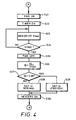
- FIG. 1 show ,in flow chart form, the operation of the present invention during bread toasting.
- step S1 the microcomputer 48 is waiting for a next operation derived from the operation switch 20 (step S2). Normal bread or frozen bread is loaded in the cooking cabinet 12. User presses the switch for toasting bread on the operation switch 20.
- the microcomputer 48 determines whether the cooking mode is toasting in a step S3. If so, the thermistor 38 detects the temperature T inside the cooking cabinet 12 in a step S4. If not, the cooking appliance 10 performs the other cooking mode at a step S5.
- the microcomputer 48 determines whether the temperature T exceeds 50°C at a step S6. If the temperature is greater than 50°C, although heater 22 does not energize, the bread is automatically toasted by the remained heat. As a result, when the bread is placed in cabinet 12, gas is promptly generated from the natural bread. But gas is not promptly generated from the frozen bread even if the temperature is high, because most gas is generated from the bread in a natural condition. It takes a while for the frozen bread to melt and to attain a natural condition. If T is less than 50° C, the fan rotates to draw outside air into the cooking cabinet 12 and to exhaust inside air with remained gas in the cooking cabinet 12 through the duct 3 (step S7).
- the timer 50 starts a count (step S8).
- the microcomputer 48 actuates the upper heater 22 and the lower heater 26 to toast the bread (step S10).
- the bread is toasted, moisture comes from the bread.
- Moisture flows nearby the gas sensor 36 in the duct 34 with air inside the cabinet 12 due to the rotation of the fan 40.
- the gas sensor 36 has been detecting the gas density, that is, relative volume of moisture since the heaters 22 and 26 started to heat the bread.
- the microcomputer 48 receives the data level Vo from the gas sensor 36 in accordance with the gas density.
- the microcomputer 48 sets Vmax, which is the peak value of the data level Vo in the thirty seconds after actuating the heaters 22 and 26, and the microcomputer 48 memorizes the Vmax (step S11 and S12).
- the microcomputer 48 calculates a change rate ⁇ , which is a ratio Vo to Vmax (step S13).
- the microcomputer 48 determines whether the change rate ⁇ exceeds 0.98 (step S14). If not, the microcomputer 48 sets a toasting time ta, which is suitable for the normal bread (step S15). If so, the microcomputer 48 sets a toasting time tb, which is suitable for the frozen bread (step S16).
- a critical level for ⁇ has been determined by a experiment to be 0.98. Toasting times ta and tb are also decided by experiment for example, ta is four minutes ten seconds, and tb is four minutes thirty seconds.
- step S15 or S16 the fan 40 stops the rotation thereof (step S17).
- the heaters 22 and 26 toast the bread for the set time, ta or tb (step S18).
- step S19 the heaters 22 and 26 stop toasting the bread (step S19).
- the timer 50 is reset (step S20).
- the flow jumps to a step S21, and the fan rotates.
- the timer 50 starts the counts (step S22).
- the gas sensor 36 has been detecting the gas density, that is, relative volume of moisture since the timer 50 started the counts. As the temperature is high enough, moisture comes from the bread without heating the heater 22 and 26. Moisture flows nearby the gas sensor 36 in the duct 34 due to the rotation of the fan 40.
- the microcomputer 48 receive the data level Vo from the gas sensor 36 in accordance with the gas density.
- the microcomputer 48 sets Vmax, which is the largest value among the data level Vo for ten seconds from the beginning of actuating the heaters 22 and 26, and the microcomputer 48 memorizes the Vmax (step S23 and step S24).
- the fan 40 stops the rotation thereof (step S25).
- the microcomputer 48 calculates a change rate ⁇ , which is a ratio Vo to Vmax (step S26). The microcomputer 48 determines whether the change rate ⁇ exceeds 0.98 (step S27). If not, the microcomputer 48 sets a toasting time tc, which is suitable for the normal bread when the cooking appliance 10 is used continuously (step S28). If so, the microcomputer 48 sets a toasting time td, which is suitable for the frozen bread when the cooking appliance 10 is used continuously (step S29). After that, the heaters 22 and 26 start to toast the bread (step S30). The flow returns back to the step S18, so that the heaters 22 and 26 toast the bread for the set time, tc or td.
- the microcomputer 48 determines whether the bread is normal or frozen, based on a gas sensor reading ten seconds after the beginning of detecting gas density.
- Toasting time tc and td are controlled based upon experimental results previously obtained, for example, tc is three minutes ten seconds, and td is three minutes thirty seconds in a preferred embodiment.
- the microcomputer 48 changes the decision time at which the determination as to frozen or unfrozen bread is made from thirty seconds to ten seconds. That is, when the cooking appliance 10 is used continuously, the decision time is earlier.
- the decision time is proper whether the cooking appliance 10 is used continuously or not. Therefore, the cooking appliance 10 toasts the bread properly whether the bread is normal or frozen, and whether the cooking appliance is used continuously or not.
- any gas in the cooking cabinet 12 remaining from a previous toasting is exhausted by fan 40.
- the gas sensor 36 detects the gas which comes from the bread actually being toasted now. While the gas sensor 36 detects gas, gas always flows nearby the gas sensor due to the forced draft by the fan 40. As a result, the gas sensor 36 can promptly detect the gas which comes from the bread, the detecting by the gas sensor can be stabilized.
- the maximum value of data level Vo while the cooking appliance 10 works can be set to the Vmax.
- a position of the thermistor 38 is changeable, if the thermistor 38 substantially detects the temperature within the cooking cabinet 12 or of the cooking cabinet.
- microcomputer 48 changes a period of cooking in accordance with a condition of the food.
- the microcomputer may change a heating power of heaters 22 and 26. For example, if a piece of bread is determined to be frozen, heaters 22 and 26 may provide additional power than if the bread were determined to be normal (un-frozen) bread.
- microcomputer 48 may change a temperature in cabinet 12 in accordance with the determined condition of the food. For example, if a piece of bread were determined to be frozen, the temperature in cabinet 12 would be set higher than if the bread were determined to be normal (unfrozen) bread.
Landscapes
- Engineering & Computer Science (AREA)
- Chemical & Material Sciences (AREA)
- Combustion & Propulsion (AREA)
- Mechanical Engineering (AREA)
- General Engineering & Computer Science (AREA)
- Electric Ovens (AREA)
Claims (12)
- Kochvorrichtung, umfassend:a) ein Kochgehäuse zur Aufnahme von Nahrung, die gekocht werden soll;b) eine Heizvorrichtung zum Erhitzen der in dem Kochgehäuse aufgenommenen Nahrung;c) ein Feuchtigkeitssensor zum Messen der Feuchtigkeit im Gehäuse;d) eine Temperaturmeßvorrichtung zum Messen der Temperatur im Kochgehäuse; unde) eine Kochregulierungsvorrichtung, die auf den Feuchtigkeitssensor und die Temperaturmeßvorrichtungen reagiert, mit der die Heizvorrichtung derart reguliert wird, daßdie Heizvorrichtung entsprechend der Feuchtigkeit reguliert wird, die während eines ungefähr am Anfang des Kochvorgangs beginnenden ersten vorbestimmten Zeitraums gemessen wird, sofern die Temperatur nicht größer als eine voreingestellte Temperatur ist, unddie Heizvorrichtung entsprechend der Feuchtigkeit reguliert wird, die während eines ungefähr am Anfang des Kochvorgangs beginnenden zweiten vorbestimmten Zeitraums gemessen wird, sofern die Temperatur größer als die voreingestellte Temperatur ist, wobei der zweite Zeitraum länger als der erste ist, und beide Zeiträume nach einem anfänglichen schnellen Absinken der Feuchtigkeitsentstehung durch anfangs ungefrorenens Brot enden.
- Kochvorrichtung nach Anspruch 1, worin die Temperaturmeßvorrichtung Vorrichtungen umfaßt, mit denen die Temperatur im Kochgehäuse zu Beginn des Kochens gemessen wird.
- Kochvorrichtung nach Anspruch 1, worin die Kochregulierungsvorrichtung auf ein Signal von dem Gassensor hin einen Nahrungszustand bestimmt.
- Kochvorrichtung nach Anspruch 1, worin die Kochregulierungsvorrichtung einen Kochzeitraum reguliert.
- Kochvorrichtung nach Anspruch 3, worin der Zustand der Nahrung davon abhängt, ob sie gefroren ist oder nicht.
- Kochvorrichtung nach Anspruch 1, worin die Kochregulierungsvorrichtung die Leistung der Heizvorrichtung reguliert.
- Kochvorrichtung nach Anspruch 1, worin die Kochregulierungsvorrichtung die Temperatur in dem Kochgehäuse reguliert.
- Verfahren zum Betreiben einer Kochvorrichtung zum Kochen, die von dem Typ ist, daß sie enthält ein Kochgehäuse zur Aufnahme von Nahrung, die gekocht werden soll, ein Heizgerät zum Erhitzen der in dem Kochgehäuse aufgenommenen Nahrung, einen Feuchtigkeitssensor, der die Feuchtigkeit in dem Kochgehäuse mißt, und Vorrichtungen zum Bestimmen einer Nahrungsart auf ein Signal von dem Feuchtigkeitssensor hin, umfassend die Schritte:Bestimmen der Temperatur im Kochgehäuse,Einstellen eines ersten vorbestimmten Zeitraumes, der ungefähr am Anfang eines Kochvorganges beginnt, während dem der Feuchtigkeitssensor die Feuchtigkeit in dem Gehäuse mißt, sofern die Temperatur nicht größer als eine voreingestellte Temperatur ist, oder Einstellen eines zweiten vorbestimmten Zeitraumes, der ungefähr am Anfang eines Kochvorganges beginnt, sofern die Temperatur größer als eine voreingestellte Temperatur ist, wobei der zweite Zeitraum länger als der erste ist und beide Zeiträume nach einem anfänglichen schnellen Absinken der Feuchtigkeitsentstehung durch anfangs ungefrorenens Brot enden,Messen von Gas in einem eingestellten Zeitraum,Bestimmen eines Nahrungszustandes aufgrund des gemessenen Gases, undRegulieren der Heizvorrichtung entsprechend der Bestimmung.
- Verfahren nach Anspruch 8, wobei die Heizdauer der Heizvorrichtung in dem Regulierungsschritt reguliert wird.
- Verfahren nach Anspruch 8, wobei die Leistung der Heizvorrichtung in dem Regulierungsschritt reguliert wird.
- Verfahren nach Anspruch 8, wobei die Temperatur in dem Kochgehäuse in dem Regulierungsschritt reguliert wird.
- Verfahren nach Anspruch 8, worin die Temperatur zu Beginn des Kochens gemessen wird.
Applications Claiming Priority (2)
| Application Number | Priority Date | Filing Date | Title |
|---|---|---|---|
| JP4134935A JP2937623B2 (ja) | 1992-05-27 | 1992-05-27 | 加熱調理装置 |
| JP134935/92 | 1992-05-27 |
Publications (2)
| Publication Number | Publication Date |
|---|---|
| EP0576145A1 EP0576145A1 (de) | 1993-12-29 |
| EP0576145B1 true EP0576145B1 (de) | 1997-03-19 |
Family
ID=15140002
Family Applications (1)
| Application Number | Title | Priority Date | Filing Date |
|---|---|---|---|
| EP93304016A Expired - Lifetime EP0576145B1 (de) | 1992-05-27 | 1993-05-25 | Kochvorrichtung mit Gassmesswertgeber |
Country Status (4)
| Country | Link |
|---|---|
| US (1) | US5319171A (de) |
| EP (1) | EP0576145B1 (de) |
| JP (1) | JP2937623B2 (de) |
| KR (1) | KR960002811B1 (de) |
Families Citing this family (21)
| Publication number | Priority date | Publication date | Assignee | Title |
|---|---|---|---|---|
| US5620624A (en) * | 1988-05-19 | 1997-04-15 | Quadlux, Inc. | Cooking method and apparatus controlling cooking cycle |
| US5726423A (en) * | 1988-05-19 | 1998-03-10 | Quadlux, Inc. | Apparatus and method for regulating cooking time in a radiant energy oven |
| US5883362A (en) * | 1988-05-19 | 1999-03-16 | Quadlux, Inc. | Apparatus and method for regulating cooking time in a lightwave oven |
| US5282582A (en) * | 1989-04-28 | 1994-02-01 | Teijin Seiki Co., Ltd. | Yarn traversing apparatus |
| JPH0674453A (ja) * | 1992-08-31 | 1994-03-15 | Toshiba Corp | 加熱調理器 |
| JPH06137561A (ja) * | 1992-10-26 | 1994-05-17 | Toshiba Corp | 加熱調理器 |
| KR960007113B1 (ko) * | 1993-09-28 | 1996-05-27 | 엘지전자주식회사 | 전자레인지의 자동해동 방법 |
| US6011242A (en) * | 1993-11-01 | 2000-01-04 | Quadlux, Inc. | Method and apparatus of cooking food in a lightwave oven |
| EP0673182B1 (de) * | 1994-03-18 | 2000-03-29 | Lg Electronics Inc. | Verfahren zur automatischen Steuerung eines Mikrowellenofens |
| GB2293027A (en) * | 1994-09-07 | 1996-03-13 | Sharp Kk | Apparatus for and method of controlling a microwave oven |
| KR0146126B1 (ko) * | 1994-12-16 | 1998-08-17 | 구자홍 | 전자레인지의 가열시간 제어장치 및 방법 |
| KR0154643B1 (ko) * | 1995-09-29 | 1998-11-16 | 배순훈 | 증기센서의 출력신호를 이용한 적응 제어방법 |
| US5844207A (en) * | 1996-05-03 | 1998-12-01 | Sunbeam Products, Inc. | Control for an electric heating device for providing consistent heating results |
| US6133558A (en) * | 1996-06-24 | 2000-10-17 | Matsushita Electric Industrial Co., Ltd. | Microwave steam heater with microwave and steam generators controlled to equalize workpiece inner and surface temperatures |
| US5705791A (en) * | 1996-12-20 | 1998-01-06 | Whirlpool Corporation | Automatic toaster and a control therefor |
| US6013900A (en) | 1997-09-23 | 2000-01-11 | Quadlux, Inc. | High efficiency lightwave oven |
| US5958271A (en) | 1997-09-23 | 1999-09-28 | Quadlux, Inc. | Lightwave oven and method of cooking therewith with cookware reflectivity compensation |
| US7351939B2 (en) | 2004-03-19 | 2008-04-01 | Whirlpool Corporation | Toaster |
| US9357878B2 (en) * | 2010-02-25 | 2016-06-07 | Bonnie Lee Buzick | Grill with safety system |
| US10682014B2 (en) * | 2013-07-09 | 2020-06-16 | Strix Limited | Apparatus for heating food |
| GB201500342D0 (en) | 2015-01-09 | 2015-02-25 | Strix Ltd | Apparatus for heating food |
Family Cites Families (13)
| Publication number | Priority date | Publication date | Assignee | Title |
|---|---|---|---|---|
| JPS55119391A (en) * | 1979-03-06 | 1980-09-13 | Sharp Kk | Cooking oven |
| AU524379B2 (en) * | 1979-07-20 | 1982-09-16 | Matsushita Electric Industrial Co., Ltd. | Control of food heating |
| DE3066593D1 (en) * | 1979-08-17 | 1984-03-22 | Matsushita Electric Industrial Co Ltd | Heating apparatus with sensor |
| JPS5640029A (en) * | 1979-09-07 | 1981-04-16 | Matsushita Electric Ind Co Ltd | Method and apparatus for controlling food heating |
| US4476372A (en) * | 1983-02-04 | 1984-10-09 | Prucher Bryan P | Spot welding electrode |
| SU1118503A1 (ru) * | 1983-07-13 | 1984-10-15 | Ленинградский Филиал Всесоюзного Института По Проектированию Организации Энергетического Строительства "Оргэнергострой" | Электрод дл контактной точечной сварки |
| JPS61143630A (ja) * | 1984-12-14 | 1986-07-01 | Sharp Corp | 加熱器 |
| US4588870A (en) * | 1984-12-18 | 1986-05-13 | Scm Corporation | Resistance welding electrode cap |
| JPS623885A (ja) * | 1985-06-27 | 1987-01-09 | Sumitomo Metal Mining Co Ltd | 抵抗溶接用電極材料 |
| US4734555A (en) * | 1986-06-26 | 1988-03-29 | Duffers Scientific, Inc. | Method and apparatus for measuring and controlling indentation in resistance welding |
| US4678887A (en) * | 1986-07-09 | 1987-07-07 | General Motors Corporation | Method and apparatus for resistance welding |
| US4728765A (en) * | 1986-09-10 | 1988-03-01 | Hobie Holding, Inc. | Spot welding electrode |
| US4760235A (en) * | 1987-09-24 | 1988-07-26 | Flater Anders H | Male spot welding electrode |
-
1992
- 1992-05-27 JP JP4134935A patent/JP2937623B2/ja not_active Expired - Lifetime
-
1993
- 1993-05-25 EP EP93304016A patent/EP0576145B1/de not_active Expired - Lifetime
- 1993-05-27 KR KR1019930009270A patent/KR960002811B1/ko not_active Expired - Fee Related
- 1993-05-27 US US08/067,827 patent/US5319171A/en not_active Expired - Fee Related
Also Published As
| Publication number | Publication date |
|---|---|
| JPH05322178A (ja) | 1993-12-07 |
| US5319171A (en) | 1994-06-07 |
| JP2937623B2 (ja) | 1999-08-23 |
| KR960002811B1 (ko) | 1996-02-26 |
| EP0576145A1 (de) | 1993-12-29 |
Similar Documents
| Publication | Publication Date | Title |
|---|---|---|
| US5319171A (en) | Cooking appliance with a gas sensor and temperature sensor | |
| US6140621A (en) | Toaster oven with timer display | |
| EP0268329B1 (de) | Mikrowellenofen | |
| EP2123981B1 (de) | Automatik-Backofen mit Dampferzeugungssystem | |
| EP0455169A2 (de) | Kochstelle | |
| EP0166997B1 (de) | Mikrowellenherd mit leistungsschwachem Auftau- und leistungsstarkem Kochbetrieb | |
| CA1298623C (en) | Microwave ovens and methods of cooking food | |
| EP0497546B1 (de) | Heizgerät für Lebensmittel | |
| JPH0975235A (ja) | オーブントースタ | |
| JP7361181B2 (ja) | 加熱調理器 | |
| EP0239290B1 (de) | Mikrowellenöfen und Verfahren zum Kochen von Lebensmitteln | |
| EP1535493B1 (de) | Kombinierter toaster und mikrowellenherd und steuerverfahren dafür | |
| JP2586258B2 (ja) | トースターレンジ | |
| JPH0674453A (ja) | 加熱調理器 | |
| JP2001193941A (ja) | 加熱調理器 | |
| JPH06307647A (ja) | 高周波加熱装置 | |
| JP2786754B2 (ja) | 加熱調理器 | |
| KR100499478B1 (ko) | 토스터 겸용 전자레인지 및 그 제어방법 | |
| JP3678174B2 (ja) | 高周波加熱器 | |
| KR960010268B1 (ko) | 냉장고의 해동 제어방법 | |
| KR0161251B1 (ko) | 밥의 상태 선택을 제어하는 방법 | |
| JPH08121780A (ja) | 電子レンジ | |
| JPH05180446A (ja) | 加熱調理器の調理制御装置 | |
| JPH0616736B2 (ja) | 炊飯ジャー | |
| JP3245511B2 (ja) | 電子レンジ |
Legal Events
| Date | Code | Title | Description |
|---|---|---|---|
| PUAI | Public reference made under article 153(3) epc to a published international application that has entered the european phase |
Free format text: ORIGINAL CODE: 0009012 |
|
| 17P | Request for examination filed |
Effective date: 19930618 |
|
| AK | Designated contracting states |
Kind code of ref document: A1 Designated state(s): FR GB |
|
| 17Q | First examination report despatched |
Effective date: 19950928 |
|
| GRAG | Despatch of communication of intention to grant |
Free format text: ORIGINAL CODE: EPIDOS AGRA |
|
| GRAH | Despatch of communication of intention to grant a patent |
Free format text: ORIGINAL CODE: EPIDOS IGRA |
|
| GRAH | Despatch of communication of intention to grant a patent |
Free format text: ORIGINAL CODE: EPIDOS IGRA |
|
| GRAA | (expected) grant |
Free format text: ORIGINAL CODE: 0009210 |
|
| AK | Designated contracting states |
Kind code of ref document: B1 Designated state(s): FR GB |
|
| ET | Fr: translation filed | ||
| PLBE | No opposition filed within time limit |
Free format text: ORIGINAL CODE: 0009261 |
|
| STAA | Information on the status of an ep patent application or granted ep patent |
Free format text: STATUS: NO OPPOSITION FILED WITHIN TIME LIMIT |
|
| 26N | No opposition filed | ||
| REG | Reference to a national code |
Ref country code: GB Ref legal event code: IF02 |
|
| PGFP | Annual fee paid to national office [announced via postgrant information from national office to epo] |
Ref country code: FR Payment date: 20050511 Year of fee payment: 13 |
|
| PGFP | Annual fee paid to national office [announced via postgrant information from national office to epo] |
Ref country code: GB Payment date: 20060524 Year of fee payment: 14 |
|
| REG | Reference to a national code |
Ref country code: FR Ref legal event code: ST Effective date: 20070131 |
|
| GBPC | Gb: european patent ceased through non-payment of renewal fee |
Effective date: 20070525 |
|
| PG25 | Lapsed in a contracting state [announced via postgrant information from national office to epo] |
Ref country code: FR Free format text: LAPSE BECAUSE OF NON-PAYMENT OF DUE FEES Effective date: 20060531 |
|
| PG25 | Lapsed in a contracting state [announced via postgrant information from national office to epo] |
Ref country code: GB Free format text: LAPSE BECAUSE OF NON-PAYMENT OF DUE FEES Effective date: 20070525 |