EP0577068B1 - Machine de pliage - Google Patents
Machine de pliage Download PDFInfo
- Publication number
- EP0577068B1 EP0577068B1 EP19930110345 EP93110345A EP0577068B1 EP 0577068 B1 EP0577068 B1 EP 0577068B1 EP 19930110345 EP19930110345 EP 19930110345 EP 93110345 A EP93110345 A EP 93110345A EP 0577068 B1 EP0577068 B1 EP 0577068B1
- Authority
- EP
- European Patent Office
- Prior art keywords
- devices
- bending
- holding
- horizontal
- cylinder
- Prior art date
- Legal status (The legal status is an assumption and is not a legal conclusion. Google has not performed a legal analysis and makes no representation as to the accuracy of the status listed.)
- Expired - Lifetime
Links
- 238000005452 bending Methods 0.000 title claims description 169
- 229910052751 metal Inorganic materials 0.000 claims description 49
- 239000002184 metal Substances 0.000 claims description 49
- 238000000034 method Methods 0.000 claims description 42
- 230000008569 process Effects 0.000 claims description 37
- 230000033001 locomotion Effects 0.000 claims description 29
- 238000010276 construction Methods 0.000 claims description 27
- 230000008878 coupling Effects 0.000 claims description 26
- 238000010168 coupling process Methods 0.000 claims description 26
- 238000005859 coupling reaction Methods 0.000 claims description 26
- 238000006073 displacement reaction Methods 0.000 claims description 22
- 230000004888 barrier function Effects 0.000 claims description 13
- 230000008859 change Effects 0.000 claims description 12
- 125000006850 spacer group Chemical group 0.000 claims description 12
- 238000012546 transfer Methods 0.000 claims description 9
- 230000007246 mechanism Effects 0.000 claims description 8
- 238000003780 insertion Methods 0.000 claims description 7
- 238000005259 measurement Methods 0.000 claims description 7
- 238000003825 pressing Methods 0.000 claims description 6
- 230000001360 synchronised effect Effects 0.000 claims description 6
- 230000003287 optical effect Effects 0.000 claims description 5
- 230000002441 reversible effect Effects 0.000 claims description 4
- 230000001502 supplementing effect Effects 0.000 claims description 3
- 230000009471 action Effects 0.000 claims description 2
- 230000000295 complement effect Effects 0.000 claims description 2
- 210000000080 chela (arthropods) Anatomy 0.000 claims 2
- 230000004048 modification Effects 0.000 claims 2
- 238000012986 modification Methods 0.000 claims 2
- 238000004873 anchoring Methods 0.000 claims 1
- 230000001939 inductive effect Effects 0.000 claims 1
- 238000009877 rendering Methods 0.000 claims 1
- IHQKEDIOMGYHEB-UHFFFAOYSA-M sodium dimethylarsinate Chemical class [Na+].C[As](C)([O-])=O IHQKEDIOMGYHEB-UHFFFAOYSA-M 0.000 claims 1
- 238000012937 correction Methods 0.000 description 12
- 238000004519 manufacturing process Methods 0.000 description 10
- 230000000903 blocking effect Effects 0.000 description 9
- 230000008901 benefit Effects 0.000 description 8
- 238000007792 addition Methods 0.000 description 6
- 230000006835 compression Effects 0.000 description 6
- 238000007906 compression Methods 0.000 description 6
- 238000013461 design Methods 0.000 description 5
- 239000012530 fluid Substances 0.000 description 5
- 230000037431 insertion Effects 0.000 description 5
- 238000001514 detection method Methods 0.000 description 4
- 238000012360 testing method Methods 0.000 description 4
- 238000011179 visual inspection Methods 0.000 description 3
- 238000013459 approach Methods 0.000 description 2
- 230000007547 defect Effects 0.000 description 2
- 238000011161 development Methods 0.000 description 2
- 230000018109 developmental process Effects 0.000 description 2
- 230000000694 effects Effects 0.000 description 2
- 238000007689 inspection Methods 0.000 description 2
- 238000012423 maintenance Methods 0.000 description 2
- 239000000463 material Substances 0.000 description 2
- 230000000750 progressive effect Effects 0.000 description 2
- 238000003908 quality control method Methods 0.000 description 2
- 238000003860 storage Methods 0.000 description 2
- 241001136792 Alle Species 0.000 description 1
- 206010012335 Dependence Diseases 0.000 description 1
- 229910000831 Steel Inorganic materials 0.000 description 1
- 230000001133 acceleration Effects 0.000 description 1
- 230000006978 adaptation Effects 0.000 description 1
- 238000000354 decomposition reaction Methods 0.000 description 1
- 230000005489 elastic deformation Effects 0.000 description 1
- 238000000605 extraction Methods 0.000 description 1
- 230000014509 gene expression Effects 0.000 description 1
- 229910001385 heavy metal Inorganic materials 0.000 description 1
- 230000010354 integration Effects 0.000 description 1
- 238000011835 investigation Methods 0.000 description 1
- 239000003973 paint Substances 0.000 description 1
- 238000000926 separation method Methods 0.000 description 1
- 229910001220 stainless steel Inorganic materials 0.000 description 1
- 239000010935 stainless steel Substances 0.000 description 1
- 239000010959 steel Substances 0.000 description 1
- 230000000007 visual effect Effects 0.000 description 1
Images


Classifications
-
- B—PERFORMING OPERATIONS; TRANSPORTING
- B21—MECHANICAL METAL-WORKING WITHOUT ESSENTIALLY REMOVING MATERIAL; PUNCHING METAL
- B21D—WORKING OR PROCESSING OF SHEET METAL OR METAL TUBES, RODS OR PROFILES WITHOUT ESSENTIALLY REMOVING MATERIAL; PUNCHING METAL
- B21D5/00—Bending sheet metal along straight lines, e.g. to form simple curves
- B21D5/04—Bending sheet metal along straight lines, e.g. to form simple curves on brakes making use of clamping means on one side of the work
- B21D5/045—With a wiping movement of the bending blade
-
- B—PERFORMING OPERATIONS; TRANSPORTING
- B21—MECHANICAL METAL-WORKING WITHOUT ESSENTIALLY REMOVING MATERIAL; PUNCHING METAL
- B21D—WORKING OR PROCESSING OF SHEET METAL OR METAL TUBES, RODS OR PROFILES WITHOUT ESSENTIALLY REMOVING MATERIAL; PUNCHING METAL
- B21D5/00—Bending sheet metal along straight lines, e.g. to form simple curves
- B21D5/02—Bending sheet metal along straight lines, e.g. to form simple curves on press brakes without making use of clamping means
- B21D5/0209—Tools therefor
- B21D5/0236—Tool clamping
-
- B—PERFORMING OPERATIONS; TRANSPORTING
- B21—MECHANICAL METAL-WORKING WITHOUT ESSENTIALLY REMOVING MATERIAL; PUNCHING METAL
- B21D—WORKING OR PROCESSING OF SHEET METAL OR METAL TUBES, RODS OR PROFILES WITHOUT ESSENTIALLY REMOVING MATERIAL; PUNCHING METAL
- B21D5/00—Bending sheet metal along straight lines, e.g. to form simple curves
- B21D5/04—Bending sheet metal along straight lines, e.g. to form simple curves on brakes making use of clamping means on one side of the work
- B21D5/047—Length adjustment of the clamping means
Definitions
- the invention relates to a bending machine for plates of the type mentioned in the preamble of claim 1 and a method for operating such a bending machine.
- a bending machine is known from EP-B1-0 105 091.
- Sheet metal bending machines are used in particular to form metal plates (for metal furniture for office and commercial purposes, for electrical household appliances, etc.) by bending the circumference of a flat sheet metal blank.
- These plate bending machines are based on a compromise between achieving the highest possible production numbers while accepting a stronger production specialization.
- one of these plate bending machines is limited to a permissible sheet thickness of 3 mm and is limited to producing a very special product from a wide range of dimensions and circumferential shapes with regard to the sheet metal blank; With such a machine, significantly higher production numbers can be achieved than can be achieved (for this product) with the aid of a conventional bending machine, which, on the other hand, offers the possibility of producing a large variety of products and working with larger sheet thicknesses.
- the sheet to be bent is clamped between the two clamping jaws or cheeks of a clamping device which forms the bending line on one of its longitudinal edges when closed, one of the clamping jaws, generally the upper one, which is also referred to as hold-down device, in Is vertically movable and actuated by cylinders which are installed between the fixed frame or frame of the machine and a carrier of the hold-down device, generally with the interposition of a guide which is provided with a double dovetail guide to achieve a connection with the carrier or the actual hold-down device, while the other jaw, generally the lower one, is fixed and is referred to as an abutment or lower beam.
- This common arrangement is the one considered below, although the precise relative arrangement of the hold-down and the abutment does not affect the essence of the present invention.
- manipulators not only replace handling that previously had to be carried out manually by operating personnel, but they can also, in combination with a central control computer which is inserted in a numerical control system (CNC), automatically and in accordance with a suitable data processing program, a sequence of feed , Retracting and rotating movements of the sheet, which are necessary to achieve a predetermined mode of operation of the bending machine.
- CNC numerical control system
- the bending machine described below is also intended to include a manipulator which is designed in accordance with a novel concept with regard to the devices for clamping and rotating the sheet metal and with regard to the devices for determining and controlling the longitudinal and angular position of the sheet metal, which in combination with a central control computer enable a very precise, reliable, fast and effective mode of operation.
- such a bending machine essentially consists of such a unit with a hold-down slide and an abutment or a lower beam, which holds the sheet immovably, the inner edge of this unit defining the bending line for a bend or an edge, which in the web one Operating strokes of an upper bending beam for making downward bends and a lower bending beam for upward bends.
- one of the improvements according to the present invention resides in the design of a bending machine which can work separately or integrated in a system with high production numbers and whose special construction is a tangential-type bending process with a high operating efficiency and a high degree of versatility with regard to the bending angle Sheet thicknesses and complicated bending processes possible
- the machine should be provided with auxiliary devices for automatic feeding and positioning of the sheets on the work table for their correct fixing by the hold-down abutment unit.
- the operating sequence of the bending machine consists in the introduction of the sheet metal blank and the successive bending of all or part of the edges of this sheet metal blank in accordance with the bent plate to be produced.
- the subsequent bending of the remaining sides requires that the active length of the hold-down be adjusted with great accuracy to the length of the bending to be carried out is; if the hold-down device is larger than the side to be bent, the bending of this edge is impeded by the edge which has already been bent over at least one adjacent side, and if the hold-down device is shorter, the bending line defined by this hold-down device does not extend over the entire area to be bent The edge would extend and the turn would be faulty outside the limits defined by the hold-down.
- hold-down devices with a modular construction are provided, which have a central section, two end sections, and two adjacent, specially shaped (longitudinal and transverse -) Edges are formed, which are provided with lips, and optionally inserted additional sections for changing the length of the hold-down device.
- the minimum operating length of the hold-down device is equal to the length that results from the central section and the two end sections, and greater lengths result from the insertion of additional sections.
- Known sheet metal manipulation and feeding devices in bending machines generally comprise a holder which can be moved back and forth in the longitudinal direction perpendicular to the vertical plane along which the bending tools are actuated.
- the movable bracket has a large opening for the passage of the sheet and comprises a clamping unit which consists of two half-jaws, which are arranged above and below the sheet, which is supported on the horizontal plane of the work table.
- the half jaws are actuated in the vertical direction to clamp the sheet and then serve to produce rotations and longitudinal displacements which initiate the arrangement of the sheet in the exact working position, after which the secure fixing during the bending process is ensured.
- the movement of the sheet in the transverse direction is not provided for in the manipulation because it is considered to be constant and is initially determined when the sheet is fed over one side of the plane of the work table, with the aid of devices which are dealt with below.
- a clamping unit is known (IT patent P 10 86 365 under the name Salvagnini Transferica SpA), in which the lower half jaw is arranged on the active side coplanar with the horizontal working plane and with a rotary drive device is provided, while the upper half-jaw is provided with a vertical actuating device for the detection and release of the sheet and is freely rotatably fastened to follow the rotation caused by the drive of the lower half-jaw and transmitted via the pressing of the sheet.
- a single clamping device is used for gripping the sheet and for subsequent entrainment in the longitudinal and angular directions.
- the exact positioning of the sheet which is essential for obtaining a correct result, largely depends on the accuracy with which the starting position of the sheet is determined when it is fed onto the work table and before it is gripped by the clamping device.
- the tangential bending process is the one that gives the least friction between the bending cheek and the sheet, which leads to a high quality without scoring in the sheet, so that this process is suitable for bending pre-painted sheets.
- Machine designs are known for this bending process (EP-A-0 293 964 in the name of Salvagnini Transferica SpA), in which the two bending cheeks, namely the upper (for a downward turn) and lower (for a upward turn) on the edges of a one-piece mounting slide having a 'C' -shaped cross section, which during operation is pivoted up and down by a number of vertical hydraulic cylinders around a single axis of rotation at the rear.
- a first problem with this arrangement is that the tangential conditions during the bending are faulty (same axis of rotation for two bending cheeks in the same rigid support), which leads to it being itself Bends at a right angle (90 °), which comprise the majority of the bends to be carried out, are necessary to combine the angular rotation for the actual tangential bending process with an extension movement of the turning radius, so that the difference in dimensions resulting from the incorrect tangency is corrected .
- This correction does not occur in idle mode, but during the application of the worker, which means that, in addition to the functional complexity that results, it is necessary to perform an operational sequence which, as a direct consequence, results in a slower operating sequence.
- the said hold-down carriage has a bridge-shaped construction which is articulated on its rear side in such a way that the active edge of the hold-down device performs an arcuate working stroke.
- the invention has for its object to provide a bending machine of the type mentioned above, which allows a substantial acceleration of the bending processes for the production of plates and can be operated with high precision by an automatic control.
- the configuration of the bending machine according to the invention makes it possible to automatically adjust the length of the hold-down device without external magazines for the additional sections, it also being possible to determine the exact length of the hold-down device that is required at any time.
- the hold-down device is formed by a central section, to which two end sections may be arranged with the insertion of intermediate additional sections, with the special feature that at least one elastic section is provided between this central section and each end section and in combination with the mentioned additional sections which is formed by a package of interconnected segments of reduced thickness, elastic spacing elements being arranged between these segments, which define respective uniform distances between these segments, external devices exerting a force counteracting the force of the spacing elements, and limiting devices for the maximum distance between the individual segments are provided.
- the hold-down element gives a continuous pressure over its entire length, which results in problems of adjusting the length of this hold-down, which lead to solutions with complicated Combinations of parts and handling.
- the novel concept of the hold-down device is formed by making an elastic length adjustment, the contact surface of the edge not being continuous, but being interrupted by the individual distances that exist between the individual segments, which, on the other hand, results in a technique that solves the problems of length adjustment, which is a complete break with the previously used concept of the need for a hold-down with a continuous surface.
- One of the sheet qualities examined was the usual steel sheet with 40 kg per square mm and sheet thicknesses of 0.5, 1, 1.5 and 2 mm, with respective distances of 0.5 and 1 mm between the respective segments of the elastic sections when the sheets were finished were used that were painted or not painted.
- a subsequent tactile check and a visual check showed a perfect quality of the bend without any defects being found and with a finish of the edges which was indistinguishable from that which was achieved using hold-down devices with a continuous surface .
- the described invention can be applied very generally, according to a preferred embodiment it is provided that two elastic sections are used, which are arranged on respective sides of the central section and each have the possibility of a change in length of 9 mm. This results in a more than sufficient margin so that one of the various possible combinations with additional sections can be found very quickly, which gives a certain length in the area of the change in length of the elastic sections. Accordingly, the length adjustment process can be significantly shortened, resulting in a corresponding increase in productivity, while further reducing the requirements for a magazine and automatic transfer and transport devices for these additional sections. In many cases, this includes no longer having to change the additional sections.
- the most appropriate design solution with regard to other conditions remains an uncovered area of change because the intermediate additional sections are all the same and have a width of 20 mm, while the entire adjustment range of each elastic Package of individual segments is 9 mm, so that each symmetrical half of the hold-down device cannot cover a range of 10 mm when moving to a subsequent additional section of 20 mm (additional or less).
- a hold-down is formed which, in its overall span, comprises all and each of the various modular sections (middle section, elastic sections, additional sections and end sections) that come into play in any case, it being stipulated that the end sections are those which change their relative position and which in any case determine the different operating lengths of the hold-down device on the basis of their specific position. Except in the event that the maximum possible length (due to the construction of the hold-down device) is used, the total length of the hold-down device which is only active is generally that which lies between the end sections mentioned.
- the end portions have two adjacent sides (longitudinal and transverse or lateral edges) which are provided with lips and which are integrally connected to a head which selectively locks against the guide carrying the hold-down device enables, and which can be coupled or moved via automatic devices connected to the hold-down device.
- This head is further provided with a spacer section, which makes it possible to maintain a gap between the spacer section and the end section, which is intended to make the side or transverse edge of the end section effective (for the successive bending of two adjacent sides of the sheet metal blank) different dimensions), with the peculiarity that this distance can be selectively formed or eliminated, even during the work process, which results in great versatility in use.
- an additional additional section with a length of 10 mm, which covers the dimensional jump, which still interrupts the continuous and progressive length adjustment and which results from the use of additional sections of 20 mm with a possibility of a Changing the length of each elastic section by 9 mm results.
- the novel device described can form a bending machine with a hold-down device, the operating length (between a constructively defined minimum and maximum value) can be set in a continuous and progressive manner and can be controlled automatically by numerical control systems, which enables maximum values of the operating sequence conceptually simplifying length adjustment (which is also automatic) and avoiding any downtime, getting the maximum possible result from the compromise of the high production specialization of the machine and avoiding the use of a magazine for additional sections.
- the additional eccentric clamping and rotating device for the sheet metal is formed by a clamping device which is formed by two conical clamping jaws, which are active over their lateral surface, the upper conical clamping jaw being freely rotatable is attached to the tip of a vertically adjustable piston rod of a second fluid cylinder, while the lower conical jaw is attached to an inclined axis of rotation, the rotation of which is synchronized with that of the lower central jaw.
- the presence of the second clamping and rotary drive device enables the force transmitted by the rotation to be comparatively much smaller, which results in a lower tendency to a relative displacement, which facilitates the precise handling of even heavy metal sheets and also with regard to the resistance of the materials and in It is desirable to avoid damage and make the machine more durable. Because there are no relative shifts, the main advantage is that the vertical shifts Longitudinal and rotary motion measurements related to the axis of the central clamping device correspond exactly to the actual conditions and the resulting working process takes place with greater precision.
- the final accuracy depends not only on the movements to be carried out but also on the correct initial positioning of the sheet.
- the present invention addresses this problem as well, but not by achieving precision by determining the initial reference position related to the center of the sheet metal plate, but by designing a measurement and detector system that automatically corrects can introduce so that the clamping point can be used as a theoretical reference center for the movements at which the central clamping device acts.
- detector and measuring devices are provided for the positioning of the sheet, which comprise the following parts: a mechanical stop, which is on the side opposite the feed of the sheet on the work table, and the one opposite the piston rod third fluid-actuated cylinder is arranged, which ensures that the sheet comes to rest against the stop, an optical measuring ruler, which detects and measures the longitudinal position of the stroke of the movable bracket in which the central clamping device clamps the sheet, and the data to the supplies central control computer, a vertical laser beam barrier, which is arranged in accordance with the bending plane and determines the position of the front edge of the sheet and transfers this data to the computer, on the one hand for possible correction of the work program of the computer, by being theoretical central e Reference position, which is used for the longitudinal measurements on the sheet, the actual position at which the clamping device has gripped the sheet is used, provided that the front edge of the sheet simultaneously interrupts this entire laser barrier or on the other hand for detection a tilting of the sheet if part of the laser barrier is excited before
- This special arrangement gives the advantage of achieving a fast and precise method of operation because it is now no longer necessary to grasp the sheet exactly at its geometric center and to determine the position of the movable holder (or the axis of the central clamping device) because now the sensor system, which is formed by the angle encoder, the optical measuring ruler and the laser barrier in combination with the control computer, carries out the precise dimensional corrections on the internal data, which forms the basis for the measurement of the actual longitudinal and angular positions by these sensors with respect to the axis form the central tensioning device.
- This new system converts the actual clamping point of the sheet into a theoretical reference center for the movements, and this is done for each edge of the sheet on the first occasion when it approaches the laser barrier.
- the aforementioned correction of the initial angular error is carried out, whereupon this laser barrier determines whether the edge is correctly aligned, and if this is not the case, a corresponding correction is carried out on the computer data.
- a tangential bending method is used in the bending machine according to the invention, in which the upper and lower bending webs are individually held on two independent swivel arms which are driven at their front end (facing the hold-down device) and via their outer sides by respective vertical hydraulic cylinders, by an upper hydraulic cylinder for the upper bending beam and a lower hydraulic cylinder for the lower bending beam.
- These swivel arms in turn have axes of rotation parallel to the bending cheeks, which are fastened in slides which can carry out a horizontal movement transversely to the bending cheeks.
- These carriages have horizontal mechanical pressure devices for adapting the point of application of the bending cheeks to the thickness of the sheet to be bent and horizontal hydraulic pressing devices for actuating the bending cheeks when bending edges beyond a right angle.
- a first advantage of this novel construction is the achievement of perfect tangential conditions which enable bends up to the right angle to be made only by a pivoting movement of the arm supporting the bending cheek, without any additional and successive corrective movement being required.
- a preferred construction in this regard is that the axes of rotation of the swivel arms are parallel to one another and are arranged in the vertical direction on one side of the horizontal working plane and at mutually interchanged positions, the axis of the arm supporting the upper bending beam being arranged below the horizontal plane, while the axis of the arm supporting the lower bending cheek is arranged above this horizontal plane.
- the mechanical means for horizontally pressing the carriage supporting the axes of the swivel arms comprise a fixed wedge connected to the rear of the carriage which is operatively abutted against an opposite movable wedge which is driven along a drive spindle in the axial direction fixed and driven in the direction of rotation by a motor.
- This design of the wedge system is adjusted at idle to the operating parameters (approach or removal of the bending beam) in order to achieve an adjustment to the thickness of the sheet to be processed and is correspondingly much simpler and more precise than other complicated systems with cams and other hydraulic devices that always have compressibility that affects the precision of the setting. This further leads to a decomposition of the forces, which transfers these forces to the structurally defined support elements.
- the hydraulic devices for the horizontal pressing of this carriage carrying the bending cheeks and their swivel arms preferably consist of two hydraulic cylinders, the Axis coincides with the horizontal working plane and which work between the slide and the stationary frame of the machine.
- This arrangement enables the cylinder to be effective only when a bend of more than a right angle (> 90 °) is to take place without it being necessary for the devices mentioned to adjust the thickness of the sheet to be effective , which facilitates effective operation.
- the hold-down device for fixing the sheet according to the invention is connected to devices for a straight vertical guide which are held on two vertical hydraulic cylinders which drive the hold-down device to clamp the sheet and release it after the bending process.
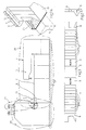
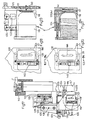
- FIG. 1 preferred embodiments of the bending machine 1 are shown, which according to FIG. 1 additionally has a customary work table 2 and a manipulator 3, by means of which sheet metal blanks 19 are brought to a suitable coordinate position, in which they are between a fixed lower beam 5 according to FIG. 2A and the movable upper beam or hold-down 4 of the bending machine, in order to form the bending edges 20, 144a of the plate to be produced successively and as shown in FIGS. 2A and 9.
- An essential feature of the invention consists in the special construction (FIG. 3) of the hold-down device 4, which according to FIGS. 4 and 5 is provided with elastic sections 9, which in this preferred embodiment have a plurality of individual segments 10 with pairs inserted between them are formed by internal elastic spacer elements 11, which are arranged in respective recesses 10a and are used to form spaces 12 according to FIG. 5a between the adjacent segments 10.
- All segments 10 are pushed onto an axially fixed spindle 13 which cooperates with a corresponding axially displaceable nut and connected to the segments 10 in such a way that when this mechanism is driven in rotation, a compression force is produced which corresponds to the force of the elastic spacer elements 11 counteracts, which are formed by rings 11, whereby their elastic deformation is caused to move adjacent segments 10 towards each other, so that they finally rest against each other according to FIG. 4A.
- This construction enables the length of the hold-down device 4 to be changed between a minimum which corresponds to the state in which all segments 10 abut one another (maximum compression) and a maximum value in which all the distances 12 between the segments add up to this minimum value be opened.
- a particularly suitable configuration consists in creating nine distances 12 with a maximum of one millimeter.
- a construction of the hold-down device 4 is considered to be particularly suitable, in which, according to FIG. 3, two elastic sections 9 and additional sections 7 are arranged on each side of a central section 6, which are required in order to take the desired length dimension into account, taking into account the end sections 8 to reach.
- this results in a length adjustment range of 18 mm, which represents the sum of the maximum distances (denoted by 26 in FIGS. 4 and 5).
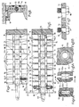
- strips 14 are provided which are attached to one of the individual segments 10 via a round hole 15 arranged in the middle and a corresponding screw 17 are attached, causing a rigid attachment of the bar 14, while for the respective adjacent individual segments 10 screws 18 are used with a smooth shaft portion, which are slidably arranged in the interior of elongated holes 16 of the bar 14, which are dimensioned so that they limit the displacement of the screw 18 (and thus of the respective individual segment) in the direction of the elastic expansion to the desired extent, as a result of which the distances 12 are thus limited to a maximum intended dimension which is the same for all distances.
- each of the individual segments 10 is related to its neighboring segment by at least one boundary strip 14, thereby ensuring that none of these segments when it is removed from the adjacent segment can exceed the limit value which is determined by the length of the corresponding elongated hole 16.
- the holding-down device 4 is held by a dovetail guide 104a with a guide 104, which in turn is fastened to a support 103 by a similar dovetail connection (with suitable blocking devices 104b for the construction), which is vertical in relation to the stationary frame 1 is displaceable with the aid of a cylinder 143, which is extended during operation.
- the devices provided for this purpose consist of a movable edge part 123 of the corresponding dovetail groove which is inserted into this head 120 is formed.
- This edge part 123 is attached to the tip of the piston rod at least one horizontal locking cylinder 122.
- two blocking cylinders 122 are preferably provided, which act on a one-piece movable edge part 123 or on two independent sections of the movable edge part 123.
- the coupling or locking devices in the head 120 consist of two snap-in cavities 121, in which associated holding devices having an elastic circumference work in the transverse direction.
- the corresponding outer coupling or locking devices are formed by two pins 133 which can be moved into these cavities 121 and the associated elastic holding devices, these pins 133 extending in the horizontal direction can move when driven by the clutch stroke of a horizontal cylinder 134 which is moved in the longitudinal displacement of the interchangeable carriage 111, the pin 133 and the cylinder 134 are installed in a coupling head 132.
- the devices for displacing the interchangeable slide 111 are formed by a horizontal spindle 113, which is fixed in the axial direction and is driven in rotation by a servo motor 114, this spindle being in threaded engagement with the actual slide 111.
- This entire construction is supported on a platform 112 which is attached to the frame 1 of the bending machine.
- two horizontal rails 126 are fastened, which interact in a sliding manner with two runners 127, which are fastened to the interchangeable slide 111.
- measures are taken which consist in the coupling pins 133 and the horizontal cylinder 134, which are combined in the coupling head 132, running on a pull-out slide 115 which can move in the vertical direction with respect to the interchangeable slide 111 and through a first vertical drive cylinder 130 is driven and guided over skids 129, which interact slidably with two vertical rails 128, which are connected to the interchangeable carriage 111.
- Performing the extraction of the interchangeable section 108 requires the use of measures for horizontal and vertical decoupling relative to the dovetail guide 104a according to FIGS. 12 and 15. These measures consist in a second horizontal decoupling stroke, which is followed by the cylinder 134 following the first latching stroke is executed as soon as the blocking cylinder (s) 122 have been retracted, causing the retraction of the moving part (s) 123.
- the decoupling stroke is larger than the horizontal extent of the intervention, which is formed by the dovetail guide 104a.
- the vertical decoupling is brought about by a second vertical cylinder 131, which runs in this carriage 115, which is installed in the interchangeable carriage.
- the measures for pulling out the end section 118 (FIGS. 12 and 16 from the front or the inactive side of the hold-down device 4) and for reinserting this end section consist of two continuous strokes of the retraction and extension of the horizontal cylinder 134, which are carried out in one way which is equal to the sum of the paths of the two successive strokes of locking the head 120 and its horizontal decoupling from the dovetail guide 104a, and which are carried out in a direction which is opposite or equal to the partial strokes mentioned said reinsertion with a handling and a sequence that is the reverse of that described above.
- At least one selector gripper 116 is provided according to FIG. 16, which can be extended horizontally and which moves with the carriage 115 and is attached to the tip of a piston rod of a horizontal drive cylinder 136.
- the selector gripper 116 is operationally at the same horizontal height as mutual grooves 142 between two additional sections 7, if the device has the position for changing or adjusting the length, in which the hold-down device 4 has been completely raised by means of its cylinder 143 and in the vertical cylinders 130 and 131 have been extended.
- This selector gripper 116 can be selectively aligned with any of the grooves 142 by means of the horizontal displacement of the interchangeable carriage 111 be, with the help of this horizontal displacement a displacement of the additional sections 7 to achieve a distance for reinserting the end section 118 can be achieved.
- this carriage 115 is preferably provided with two selector grippers 116 and corresponding cylinders 136, which are arranged symmetrically on each side of the coupling head 132 and of which one or the other can be actuated selectively when searching for the stroke, the fastest one Carrying out the opening of the distance between the additional sections 7 allows, these selector grippers 116 and the cylinders 136 are arranged at a lower height than the coupling head 132 and are held on respective vertical extensions 135 of the carriage 115.
- the devices for compressing and adjusting the active length dimension of the hold-down device 4 consist of an operating unit which is arranged beyond the maximum length that can be occupied by the hold-down device 4 and on the carrier 103 or preferably on the inserted guide 104, which supports the hold-down device, is held, this operating unit being formed by a pressing part 145 which can be pressed against the end of the hold-down device 4 and which is screwed onto a threaded spindle 109 which is fixed in the axial direction and is actuated by a servo motor 110.
- this operating unit effects the compression to eliminate the play after changing the position of the mentioned end section 118 and, on the other hand, the possible adjustment of the longitudinal dimension using the possibilities that result from each of the above-mentioned elastic sections 9.
- this interchangeable section 108 there is additionally provided a longitudinally displaceable spacing section 119 which is arranged on the outside of the end section 118, this spacing section 119 being movably connected to the head 120 via a cylinder 124 which in an operating end position causes a system between the sections 119 and 118, so that there is a continuous longitudinal edge of the hold-down 4, while in the other operating end position of this cylinder said sections 119 and 118 are separated from each other, whereby the transverse edge adjacent to active longitudinal edge of the actual end section 118 comes into effect, which provides greater operational versatility for the bending machine described.
- this construction enables all additional sections to remain on the guide 104 and no magazine is required for the temporary storage of additional sections, since the end section 118 is inserted at the appropriate position in order to achieve the correct length of the hold-down device between the additional sections and the distance between the spacing section 119 and the end section 118 makes it possible to accommodate an already bent edge of the sheet 19.
- the automatic process of the length adjustment of the hold-down device 4 is partially described below, starting from the bending working position in which the cylinder 143 is extended and presses the hold-down device 4 against the sheet 19 , wherein the two cylinders 130 and 131 are retracted and the interchangeable section 108 is operationally integrated in the hold-down device 4.
- Fig. 11 the actual blocking devices 104b of the dovetail guide 104a are shown, which are arranged in the guide 104 of the carrier 103 for the hold-down device and which are of the known type and are used to block all the elements of the hold-down device 4 during the working cycles .
- the interchangeable section 108 of the hold-down device 4 is formed by an end section 118 and a spacing section 119, it being possible for these two to be in a 'continuous' position 119a of the spacer 119 of the end section 118 to be arranged, which enables the machine to first bend the long sides of the sheet 19 in front of the short sides in a successive embodiment, thereby achieving operating options which were previously not possible.
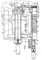
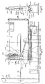
- the manipulator already mentioned has a construction with a movable holder 3 which is mounted on the frame 204 via vertical wheels 123 and horizontal wheels 124, which interact with rails 204a, so that this holder can be displaced in the longitudinal direction and perpendicular to the vertical bending plane 202 is.
- Actuators for this longitudinal displacement of the movable bracket 3 consist of a second motor 225 which transmits its rotation via a set of pulleys 226 to 227 to a horizontal ball screw nut spindle 222 which is fixed in the axial direction and whose ball nut with the base 203a of the actual movable bracket 3 is connected.
- This system has, among other things, the advantages of high operational precision and low maintenance already mentioned.
- the central clamping device 206, 207 and conical clamping jaws 215-218 move in this movable holder 3, both of which have the task of gripping the sheet 19 and moving it in the longitudinal and angular directions so that it assumes the correct operating position.
- the lower central jaw 207 and the lower conical jaw 218 are driven in synchronism with one another by a first motor 214 which, via a vertical shaft 213, rotates a horizontal shaft 212 which on the one hand drives a worm spindle which meshes with a ring gear 210 which co-operates with a shaft 209 of this lower jaw 207 is keyed, and the other hand is keyed with a pinion 212 which meshes with a pinion 220 which is fixed on the inclined axis 219 of the lower conical jaw 218.
- the central upper jaw 206 and the upper conical jaw 215 are vertically displaceable, in the first case via the piston rod 208a of a first fluid cylinder 208 and in the second case via the piston rod 216a of a second fluid cylinder 216, the outer vertical guides 217 for it Operation are assigned.
- the upper jaw 206 and the upper conical jaw 215 are at the tip of these piston rods 208a, 216a with the possibility of one attached free rotation, such that they can rotate freely to the extent caused by the lower jaw 207 and the lower conical jaw 218 as soon as the plate 19 between the one (206, 215) and the other (207, 218 ) was pinched, this sheet must be moved in the longitudinal and angular directions to reach the working position in which an edge or an edge fold of the sheet is to be bent.
- this novel arrangement with an additional and spaced clamping of the sheet 19 enables the sheet to be handled without sliding using lower forces, which enables effective and precise handling even with very large and heavy sheets 19 that are permitted for the bending machine 1.
- the control of the operating position of the sheet 19 or 228 is preferably achieved with the aid of the following parts: an encoder 211, which determines the rotational angle position of the shaft 209, an optical measuring rail 231 for determining the position and the actual displacement of the shaft 209, which is related to the movable bracket 3 in the direction of the bending plane 202 and moved away from it, the laser barrier 232, which is arranged in accordance with the bending plane 202, and a central control computer which processes the measured values supplied by the aforementioned elements and corresponding commands for those to be carried out Movements and to modify the data in his work program depending on what is the difference between the actual position of this shaft 209 and the theoretically intended position.
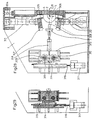
- the operation of the new construction described above begins with a feeding phase of the material, in which a plate according to FIG. 26 is moved across the width of the work table 2 with the aid of a third fluid cylinder 230, which ensures the correct contact of the plate against a stop 229 on the Opposite edge ensures whereupon the sheet 19 is simultaneously gripped by the central clamping device 206, 207 and the conical clamping jaws 215-218, so that the sheet is in a position in which it can be manipulated until its front edge is detected by the laser barrier 232.
- one of two cases can occur: either the entire front edge of the sheet is detected simultaneously by the laser barrier 232, in which case the central control computer compares the measured value of the position of the shaft 209 with the reference value provided in the program, such that that if they match, the computer starts executing the program, while if there is no match, the actual position is used as the new reference position and execution begins.
- the detector and measuring devices for the position of the sheet 19 are mechanical centering devices which are adjustable and controllable and are of a known type.
- a vertical rod 233 is provided in the vicinity of the lower conical clamping jaw 218, which in the axial direction under the action of a fourth fluid cylinder 234 between a lower inactive position in which the Tip of this rod is below the horizontal working plane 2, and an upper active end position is displaceable, in which this tip protrudes and presses against the sheet 19 to keep it out of contact with the Bring working level 2.
- the measures for changing the angle of the contact pressure in the upper jaw 216 are that two parallel halves 206a and 206b are provided in the direction of the height, which are connected to one another via an intermediate ball 206c, which it enables the lower halves 206b to assume variable support angles with respect to the sheet 19, whereby surface irregularities of the sheet 19 can be taken into account in this way.
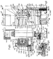
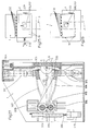
- FIG. 27 In which an upper bending cheek 205 and a lower bending cheek 306 are shown, which are individually arranged at the end of respective independent arms 307, 308, which are arranged around corresponding ones Axles 309, 310 are pivotable when the respective vertical hydraulic cylinders 311, 312 are actuated.
- the lower cylinder 312 is actuated and the lower arm 308 moves (see the dash-dotted position) towards the working plane 2 to a greater or lesser extent depending on the desired bend angle that is equal to or can be smaller than a right angle, this being the one that corresponds to the maximum movement, such that the pivoting movement of the arm 307 or 308 is sufficient for bends up to 90 °.
- this pivoting movement For bends of more than 90 °, it is necessary to combine this pivoting movement with a suitable horizontal movement in the direction of the sheet 19.
- the pivot axes 309, 310 of these arms are arranged one above the other and in the opposite manner with respect to the working plane 2.
- the distance between the bending line, which is determined by the inner edge of the unit formed from the hold-down device and the lower beam or the abutment 5, and the axes 309, 310 must be modified when idling, if necessary Adjust the point of application of the bending cheek to the thickness of the sheet 19 used and the bending angle, while it must be changed during operation in order to achieve a longitudinal movement in the event of bends of more than 90 °.
- the axes 309, 310 are fastened on a slide 313 which can be displaced in the transverse direction to the bending line.
- a motor 317 is activated for displacement in idle mode, which drives a threaded spindle 316, which is fixed in the axial direction according to FIG. 29, which drives a movable wedge 315 in the vertical direction, which causes a corresponding vertical (horizontal) movement of a fixed wedge 315, which with the Carriage 313 is connected.
- a horizontal cylinder 318 which is fastened between the slide 313 and a fixed point on the frame 1, is actuated for displacement during the working process.
Landscapes
- Engineering & Computer Science (AREA)
- Mechanical Engineering (AREA)
- Bending Of Plates, Rods, And Pipes (AREA)
Claims (36)
- Machine de pliage pour le formage de plaques de métal par pliage de la périphérie d'un flan de tôle (19) plan, comportant:
un dispositif de pliage qui comprend un dispositif de serrage et d'alignement avec une joue inférieure fixe ou un contre-appui (5) et une joue supérieure ou un serre-flan (4) mobile dans la direction verticale ainsi que des joues de pliage inférieurs et supérieure (305, 306) parmi lesquelles la joue de pliage (305) supérieure sert à réaliser des pliages vers le bas et la joue de pliage (306) inférieure des pliages vers le haut, la longueur du serre-flan (4) pouvant être adaptée à la longueur du pliage à réaliser et le serre-flan (4) présentant une construction modulaire avec un segment (6) médian de longueur fixe sur lequel peuvent être fixés deux ensembles constituées de un ou plusieurs segments (7) complémentaires de longueur prédéterminée et deux segments (118) d'extrémité qui sont pourvus d'une arête transversale prolongeant l'arête longitudinale active qui détermine le ligne de pliage et
un organe mobilede préhension ou un manipulateur (3) pour positionner la tôle (19) sur la table de travail ou dans le plan de travail (2),
caractérisée par le fait que le serre-flan (4) comporte, en plus du segment (6) intermédiaire, des segments (7) complémentaires disposés symétriquement par rapport à ce dernier et des segments (8, 108) d'extrémité, au moins un segment (9) élastique qui est constitué d'un ensemble de segments (10) distincts entre lesquels des éléments d'espacement (11) compressibles élastiquement sont disposés de manière telle que des espaces (12) réglables soient formés entre les segments (10), par le fait qu'il est prévu des dispositifs extérieurs (13; 145) pour produire une action antagoniste à la force des éléments d'espacement (11) et par le fait qu'il est prévu des dispositifs de limitation (14) pour limiter l'espace maximal entre les différents segments (10). - Machine de pliage selon la revendication 1, caractérisée par le fait qu'au moins un segment (9) élastique est placé contre le segment (6) intermédiaire.
- Machine de pliage selon la revendication 1 ou la revendication 2, caractérisée par le fait qu'un segment (9) élastique est disposé de chaque côté du segment (6) intermédiaire.
- Machine de pliage selon l'une des revendications précédentes, caractérisée par le fait que les éléments d'espacement (11) élastiques sont formés de paires de bagues (11) élastiques qui sont disposées entre des segments (10) contigus dans des évidements (10a) correspondants desdits segments (10), la profondeur totale des évidements (10a) dans deux segments (10) contigus étant au moins égale à la longueur axiale minimale de fonctionnement à laquelle une bague (11) élastique peut être amenée par compression.
- Machine de pliage selon l'une des revendications précédentes, caractérisée par le fait que les dispositifs (13) extérieurs d'action antagoniste sont constitués par un mécanisme à vis-écrou (13; 109, 110) dont la vis (13; 109) est fixe dans la direction axiale, traverse les différentes segments (10) et est en prise avec l'écrou mobile.
- Machine de pliage selon l'une des revendications précédentes, caractérisée par le fait que les dispositifs (14) de limitation de l'espacement maximal entre deux segments (10) sont constitués de barrettes (14) qui sont liées chaque fois à l'un des segments (10), dans la direction transversale, par l'intermédiaire d'une vis (17) d'ancrage fixe qui est vissée dans un trou (15) cylindrique correspondant de la barrette (14) et immobilise celle-ci vis-à-vis dudit segment (10), par le fait que la barrette est liée avec possibilité de glissement aux segments (10) voisins du segment considéré au moyen de vis (18), les vis (18) comportant une partie de tige lisse qui pénètre de manière coulissante dans des trous oblongs (16) de la barrette (14) qui s'étendent dans la direction longitudinale et par le fait que la limitation de l'espacement (12) maximal a lieu par le fait que, dans la direction correspondant à un allongement des bagues (11) élastiques, les vis (18) montées coulissantes viennent en butée contre l'extrémité du trou oblong (16) qui leur est associé.
- Machine de pliage selon l'une des revendications précédentes, caractérisée par le fait qu'il prévu pour chaque moitié symétrique du serre-flan (4) un dispositif automatique de réglage de la longueur dudit serre-flan comprenant les éléments suivants:- un segment d'extrémité (118) avec des côtés actifs longitudinaux et transversaux qui constitue une partie d'un segment (108) dont la position est interchangeable et qui est lié rigidement à une tête (120) pourvue de dispositifs de blocage par rapport à une glissière (104) portant le serre-flan (4) et de dispositifs d'encliquetage (121) qui coopèrent avec des dispositifs d'encliquetage (133) extérieurs associés,- un chariot de changement (111) qui est pourvu de dispositifs (113, 114) permettant son déplacement en fonctionnement le long du serre-flan (4) et dans lequel sont disposés les dispositifs d'encliquetage (133) extérieurs pour la tête (120) portant le segment (118) d'extrémité,- des dispositifs disposés dans le chariot de changement (111) pour positionner en fonctionnement les dispositifs d'encliquetage,- des dispositifs pour désolidariser dans la direction horizontale et dans la direction verticale le segment (118) d'extrémité par rapport à la glissière (104) portant le serre-flan (4),- des dispositifs d'extraction pour extraire le segment d'extrémité (118) sur le côté avant ou non actif du serre-flan (4) et pour remettre en place ledit segment d'extrémité à un nouvel emplacement aux fins d'adapter la longueur du serre-flan,- des dispositifs pour ouvrir un espace entre les segments complémentaires (7) afin de remettre en place le segment d'extrémité (118),- des dispositifs pour comprimer et régler la longueur du serre-flan (4)- éventuellement des dispositifs mobiles supplémentaires pour compléter de manière sélective le segment d'extrémité (118).
- Machine de pliage selon la revendication 7, caractérisée par le fait que le serre-flan (8) est tenu par l'intermédiaire d'un guidage à queue d'aronde (104a) qui est aménagé dans un support (103) portant le serre-flan (4) et/ou une glissière (104) intercalée entre le support (103) et le serre-flan (4), par le fait que le dispositif de blocage de la tête (120) par rapport au guidage à queue d'aronde (104a) est constitué par un bord latéral (123) mobile de la rainure en queue d'aronde aménagé dans la tête (120) et par le fait que ledit bord latéral (123) est relié à l'extrémité de la tige de piston d'au moins un vérin de blocage (122) horizontal.
- Machine de pliage selon la revendication 7 ou la revendication 8, caractérisée par le fait que les dispositifs d'encliquetage de la tête (120) se composent de deux cavités (121) d'enliquetage dans lesquelles sont disposés des dispositifs de retenue avec une surface extérieure élastique agissant dans la direction transversale.
- Machine de pliage selon l'une des revendications 7 à 9, caractérisée par le fait que les dispositifs d'encliquetage extérieurs coopérant avec la tête (120) sont constitués de deux tenons (133) qui coopèrent avec les cavités (121) et les dispositifs élastiques de retenue associés, par le fait que les tenons (133) peuvent être mus horizontalement par la course d'encliquetage d'un vérin (134) horizontal qui se déplace dans la direction horizontale, avec le chariot de changement (111), et par le fait que les tenons (133) et le vérin (134) sont liés l'un à l'autre par une tête (132) d'encliquetage.
- Machine de pliage selon l'une des revendications 7 à 10, caractérisée par le fait que les dispositifs de déplacement du chariot de changement (111) se composent d'une vis (113) horizontale qui est fixe dans la direction axiale, est entraînée par un servomoteur (114) et est en prise par un filetage avec le chariot de changement (111), ces éléments étant fixés sur une plateforme (112) liée au bâti (1) de la machine de pliage, deux rails (126) horizontaux sur lesquels glissent des patins (127) solidaires du chariot de changement (111) étant disposés parallèlement à la vis (113).
- Machine de pliage selon l'une des revendications 7 à 11, caractérisée par le fait que les dispositifs de réglage de la position des dispositifs d'encliquetage (133-134) sont agencés de manière telle que les dispositifs d'encliquetage liés à la tête d'encliquetage (132) sont disposés dans un chariot d'extraction (115) qui peut être déplacé verticalement par rapport au chariot de changement (111) mobile dans la direction horizontale et que ledit chariot d'extraction (115) est lié au chariot de changement (111) par l'intermédiaire d'un premier vérin (130) d'entraînement vertical et de patins (129) qui glissent dans la direction verticale sur des rails (128) verticaux liés au chariot chariot de changement (111).
- Machine de pliage selon l'une des revendications 7 à 12, caractérisée par le fait que les dispositifs pour désolidariser dans les directions verticale et horizontale le segment d'extrémité (118) par rapport au serre-flan (4) exécutent une deuxième course horizontale de désaccouplement qui est un prolongement de la première course d'encliquetage exécutée par le vérin (134) horizontal, dès que les vérins de blocage (122) ont été rentrés et ont provoqué le retrait du ou des bord(s) (123) mobile(s), par le fait que la course de désaccouplement dans la direction horizontale est supérieure à la longueur d'engagement horizontal dans le guidage à queue d'aronde (104a) et est suivie d'une course de désaccouplement verticale qui englobe un trajet vertical supérieur à la longueur d'engagement vertical dans le guidage à queue d'aronde (104a) et est provoquée par un deuxième vérin (131) vertical qui est disposé dans le chariot d'extraction (115) monté sur le chariot de changement (111).
- Machine de pliage selon l'une des revendications 7 à 13, caractérisée par le fait que l'extraction du segment d'extrémité (118) du serre-flan (4) est opérée depuis le côté avant ou non actif du serre-flan (4) et que la mise en place dudit segment d'extrémité à un nouvel emplacement est opérée par deux courses de rentrée et de sortie continues du vérin (134) horizontal exécutées avec un trajet qui est égal à la somme des trajets des courses consécuives pour l'encliquetage de la tête (120) et le désaccouplement horizontal de ladite tête par rapport au guidage à queue d'aronde (104a), ces courses se produisant dans la direction opposée ou dans la même direction que ces courses partielles.
- Machine de pliage selon l'une des revendications 7 à 14, caractérisée par le fait que les dispositifs pour ouvrir un espace entre les différents segments (7) complémentaires comprennent au moins une pince de sélection (116) qui peut être sortie dans la direction horizontale et se déplace avec le chariot d'extraction (115), par le fait que la pince de sélection est fixée à l'extrémité de la tige de piston d'un vérin d'entraînement (136) horizontal, par le fait que la pince de sélection (116) est disposée à la même hauteur horizontalement que les rainures (142) aménagées entre deux segments (7) complémentaires, par le fait que le serre-flan (4) atteint la position de changement ou la position de modification de sa longueur lorsque le serre-flan est totalement soulevé par son vérin (134), les vérins (130 et 131) verticaux étant totalement sortis, par le fait que dans cette position, la pince de sélection (116) est disposée de manière sélective en vis-à-vis de l'une quelconque des rainures (142) par un déplacement horizontal du chariot chariot de changement (111) et par le fait que ce déplacement provoque un déplacement des segments (7) complémentaires pour créer l'espace nécessaire pour l'insertion du segment d'extrémité (118).
- Machine de pliage selon l'une des revendications 7 à 15, caractérisée par le fait que les dispositifs pour comprimer et pour régler la longueur active du serre-flan (4) sont constitués d'une unité fonctionnelle qui est placée à une distance supérieure à la longueur maximale que peut prendre le serre-flan (4) et est fixée sur le support (103) et/ou sur la glissière (104) intercalée, par le fait que l'unité fonctionnelle est constituée d'un élément de pression (145) qui peut être appliqué contre l'extrémité du serre-flan (4) et est vissé sur une vis (109) fixe dans la direction axiale et entraînée par un servomoteur (110) de manière telle que ladite unité fonctionnelle provoque d'une part le resserrement nécessaire pour combler l'espace après un changement de position du segment d'extrémité (118) et à la suite de cela un réglage éventuel de la longueur, la variation de longueur autorisée par le segment élastique (9) étant utilisée.
- Machine de pliage selon l'une des revendications 7 à 16, caractérisé par le fait que les dispositifs mobiles pour compléter de manière sélective le segment d'extrémité (118) se composent d'un segment complémentaire (117) additionnel disposé dans un support (137) qui est lié au chariot (115) d'extraction par l'intermédiaire d'un vérin (138) disposé dans la direction longitudinale du serre-flan (4), par le fait que le segment complémentaire (117) additionnel peut être saisi par deux pinces (139) qui sont mues par un vérin d'actionnement (140) vertical, par le fait que le segment complémentaire (117) additionnel est amené en regard d'une position de transfert par rapport au segment d'extrémité (118) lorsque la position pour le changement de longueur est appelée, le vérin (143) étant rentré et les vérins (130 et 131) sortis, et par le fait que le segment complémentaire (117) additionnel et le segment d'extrémité (118) présentent des dispositifs à tenon et mortaise (141 - 125) complémentaires à des fins d'accouplement réciproque.
- Machine de pliage selon l'une des revendications 13 à 17, caractérisée par le fait qu'il est prévu à la place des deux vérins (130, 131) verticaux un vérin vertical unique qui peut exécuter de manière indépendante les courses de fonctionnement des cylindres distincts.
- Machine de pliage selon l'une des revendications 12 à 18, caractérisée par le fait que le chariot (115) d'extraction est pourvu de deux pinces de sélection (16) et de vérins (136) associés qui sont disposés symétriquement de part et d'autre de la tête d'encliquetage (132) et peuvent être actionnées séparément de manière sélective aux fins d'obtenir la course la plus rapide pour ouvrir l'espace entre les segments complémentaires et par le fait que les pinces de sélection sont disposées dans une position moins élevée que la tête d'encliquetage (132) et sont fixées sur des prolongements (135) verticaux correspondants du chariot d'extraction (115).
- Machine de pliage selon l'une des revendications 7 à 19, caractérisée par le fait qu'un segment d'espacement (119) additionnel, mobile dans la direction longitudinale, est disposé dans le segment (108) interchangeable, sur le côté extérieur du segment d'extrémité (118), par le fait que le segment d'espacement (119) est lié avec possibilité de déplacement à la tête (120) par l'intermédiaire d'un vérin (124) et, dans une position extrême de fonctionnement forme un appui entre les segments (119 et 118) et ainsi une continuité du bord longitudinal actif du serre-flan (4), tandis que dans l'autre position extrême, les segments (119 et 118) sont éloignés l'un de l'autre rendant ainsi actif le bord transversal qui prolonge le bord longitudinal actif du segment d'extrémité (118).
- Machine de pliage selon la revendication 20, caractérisée par le fait que le segment d'espacement prévu sur le segment d'extrémité peut être déplacé par rapport au segment d'extrémité (118), dans une-position "de continuité" (119a) du segment d'espacement (119), de sorte que la machine peut être équipée pour réaliser des opérations consécutives de pliage des grands côtés de la tôle (19) avant les petits côtés.
- Machine de pliage selon l'une des revendications précédentes, caractérisée par le fait que le manipulateur (3) comprend les éléments suivants:- des dispositifs de serrage et d'entraînement en rotation (215, 218) pour la tôle (19) qui sont disposés de manière excentrée en supplément d'un dispositif de serrage (206-207) central dont la mâchoire de serrage (206) supérieure est libre en rotation tandis que la mâchoire de serrage (207) inférieure est entraînée en rotation,- des dispositifs d'entraînement en rotation (212, 214) pour l'entraînement synchrone de la mâchoire de serrage (207) inférieure centrale et des dispositifs additionnels excentrés de serrage et d'entraînement (215, 218) pour la tôle (19),- un dispositif (211) pour la mesure directe d'angles (codeur) qui est fixé sur l'axe (209) de la mâchoire de serrage (207) inférieure centrale et coopère avec un calculateur de commande central qui contient les programmes nécessaires de commande et de correction,- des dispositifs d'actionnemente (225) pour le déplacement dans la direction longitudinale du moyen de préhension (3) mobile au moyen d'un ensemble écrou-vis à recirculation de billes (222),- des dispositifs de détection et de mesure mécaniques et électroniques pour déterminer et mesurer la position de la tôle (19) qui coopèrent avec le calculateur de commande central,- des dispositifs pour modifier l'angle d'appui, qui sont disposés dans la mâchoire de serrage (206) supérieure.
- Machine de pliage selon la revendication 22, caractérisée par le fait que les dispositifs additionnels excentrés de serrage et d'entraînement en rotation (215, 218) pour la tôle (19) se composent d'un dispositif de serrage formé de deux mâchoires de serrage (215, 218) coniques qui agissent par leur surface latérale, par le fait que la mâchoire de serrage (215) conique supérieure est montée libre en rotation à l'extrémité d'une tige de piston (216a) déplaçable verticalement appartenant à un deuxième vérin (216) à fluide, tandis que la mâchoire de serrage (218) conique inférieure est fixée sur un axe de rotation, (219) incliné qui est synchronisé avec la mâchoire de serrage (207) inférieure centrale.
- Machine de pliage selon la revendication 22 ou 23, caractérisée par le fait que les dispositifs d'entraînement en rotation synchrones de la mâchoire de serrage (207) centrale inférieure et de la mâchoire de serrage inférieure conique sont agencés de telle sorte que, sur l'arbre (209) vertical de la mâchoire de serrage (207) inférieure centrale, est fixée une couronne dentée (210) qui engrène une vis d'un arbre (212) horizontal, par le fait qu'un premier pignon (220) est fixé sur l'arbre incliné (210) de la mâchoire de serrage (218) conique inférieure, lequel pignon engrène avec un deuxième pignon (221) qui est fixé sur l'arbre (212) horizontal et par le fait que l'arbre (212) horizontal est couplé pour une rotation à un arbre (213) vertical qui est entrainé en rotation par un premier moteur (214).
- Machine de pliage selon l'une des revendications 22 à 24, caracterisée par le fait que les dispositifs d'entraînement pour le déplacement en translation du moyen de préhension (3) mobile se composent d'un deuxième moteur (225) qui, par l'intermédiaire d'un jeu de poulie à courroies (226 - 227) transmet sa rotation à un ensemble écrou-vis à recirculation de billes (222) qui est fixe dans la direction axiale et dont l'écrou est lié à la base (203a) du moyen de préhension (3) mobile à proprement parler.
- Machine de pliage selon l'une des revendications 23 à 25, caractérisée par le fait qu'une tige (233) verticale est disposée dans la région de la mâchoire de serrage (218) conique inférieure, laquelle tige peut être déplacée dans la direction axiale sous l'action d'un quatrième vérin (234) à fluide entre une position inférieure de repos dans laquelle l'extrémité de la tige est masquée sous le plan de travail (2) horizontal et une position supérieure extrême active dans laquelle l'extrémité appuie par le dessous sur la tôle (19) et soulève cette dernière du plan de travail (2).
- Machine de pliage selon l'une des revendications 22 à 26, caractérisée par le fait que les dispositifs pour modifier l'angle d'appui dans la mâchoire de serrage (206) supérieure se composent dans le sens de la hauteur, de deux parties (206a, 206b) parallèles qui sont liées l'une à l'autre par une bille (206c) placée entre deux qui permet à la partie inférieure (206b) de prendre des angles de contact variables par rapport à la tôle (19).
- Machine de pliage selon l'une des revendications 22 à 27, caractérisée par le fait que les dispositifs de détection et de mesure pour la position de la tôle (19) comprennent les éléments suivants:- une butée mécanique (229) qui est disposée sur le côté de la tôle située en vis-à-vis du côté entrée de la tôle (19) sur le plan de travail (2) et en vis-à-vis du poussoir d'un troisième vérin (230) à fluide qui agit en sorte que la dite butée (229) soit atteinte,- un rail de mesure (231) optique qui enregistre et mesure la position longitudinale du dispositif de préhension (3) mobile, dans laquelle le dispositif de serrage (206, 207) central saisit la tôle (19), ces données étant transmises à un calculateur de commande central,- un barrage (232) à faisceau laser vertical qui est disposé dans le plan de pliage (202), détecte le bord avant de la tôle (19) et transmet les données au calculateur, d'une part pour procéder à des corrections éventuelles du programme de travail du calculateur, la position effective dans laquelle le dispositif de serrage (206, 207) a effectivement immobilisé la tôle (19) et dans laquelle le bord avant de ladite tôle coupe le barrage laser (232) étant utilisée comme position de référence centrale théorique, tandis que d'autre part la tôle (19) est considérée comme mal orientée lorsqu'une partie du barrage laser est interrompue avant l'aute, situation dans laquelle un ordre pour une rotation de correction est transmis aux mâchoires de serrage (206, 207/215 - 218) et les données de la nouvelle position angulaire sont utilisées par le programme de travail comme origine pour les rotations au cours du processus de pliage à réaliser et- l'élément de mesure directe d'angle (codeur) (211) qui détermine la position angulaire de l'arbre (209) de la mâchoire de serrage(207) inférieure et fournit les données au calculateur.
- Machine de pliage selon l'une des revendications 22 a 27, caractérisée par le fait que les dispositifs de détection et de mesure pour la position de la tôle (19) comprennent des moyens mécaniques de centrage qui sont réglables et commandables.
- Machine de pliage selon l'une des revendications précédentes, caractérisée par le fait que la joue de pliage (305) supérieure et la joue de pliage (306) inférieure sont fixées séparément sur deux bras pivotants (307, 308) indépendants qui sont mus au niveau de leur extrémité antérieure et côté extérieur par des vérins hydrauliques verticaux, un vérin hydraulique (311) supérieur étant prévu pour la joue de pliage (305) supérieure et un vérin hydraulique (312) inférieur étant prévu pour la joue de pliage (306) inférieure, par le fait que les bras pivotants (307, 308) comportent des axes de rotation (309, 310) qui sont fixés parallèlement aux joues de pliage (305, 306) dans des chariots (313) mobiles dans la direction horizontale, transversalement aux joues de pliage (305, 306), et qui portent des dispositifs mécaniques horizontaux de pression pour adapter le point d'attaque des joues de pliage (305, 306) à l'épaisseur de la tôle (19) à plier et des dispositifs hydrauliques de pression pour actionner les joues de pliage (305, 306) pour les pliages supérieurs à un angle droit.
- Machine de pliage selon l'une des revendications précédentes, caractérisée par le fait que le serre-flan (4) pour la tôle (19) est pourvu de dispositifs de guidage linéaires verticaux qui sont mus par un vérin hydraulique (304) vertical aux fins de déplacer le serre-flan en direction d'une position dans laquelle la tôle (19) est bloquée et pour libérer la dite tôle à la fin du processus de pliage.
- Machine de pliage selon la revendication 30, caractérisée par le fait que les axes de rotation (309, 310) des bras pivotants (307, 308) sont parallèles entre eux et sont disposés dans des positions inversées verticalement sur les faces correspondantes du plan de travail (2) horizontal, de manière telle que l'axe (309) du bras pivotant (307) portant la joue de pliage (305) supérieure soit situé en-dessous du plan horizontal (2), tandis que l'axe (310) du bras pivotant (308) portant la joue de pliage (306) inférieure est disposé au-dessus dudit plan (2) horizontal, ce qui permet d'obtenir une position de fonctionnement tangentielle adaptée des joues de pliage (305, 306) indépendante pour chacune des joues (305, 306).
- Machine de pliage selon l'une des revendications 30, 32, caractérisée par le fait que les dispositifs de pression mécaniques horizontaux du chariot (313) portant les axes (309, 310) des bras pivotants (307, 308) sont agencés de manière telle que ledit chariot (313) est lié au niveau de sa face postérieure à une cale (314) fixe qui, en fonctionnement, est en contact avec une cale (315) mobile associée qui se déplace le long d'une vis (316) fixe dans la direction axiale et entrainée en rotation par un moteur (317).
- Machine de pliage selon l'une des revendications 30, 32, 33, caractérisée par le fait que les dispositifs de pression hydrauliques horizontaux du chariot (313) portant les axes (309, 310) se composent de deux vérins hydrauliques dont les axes sont situés dans le plan (2) de travail horizontal et qui agissent entre le chariot (313) et le bâti (1) fixe de la machine.
- Procédé d'exploitation d'une machine de pliage selon l'une des revendications précédentes, caractérisé parle fait que le changement automatique de position du segment (108) interchangeable sur la longueur du serre-flan (4) depuis la position de travail de pliage, dans laquelle le vérin (143) est sorti et le serre-flan (4) appuie sur la tôle (19), et dans laquelle les vérins (130 et 131) sont rentrés, le segment (108) interchangeable étant lié en fonctionnement au serre-flan (4), comprend les étapes suivantes:- rentré du vérin (143) qui porte le support (103) pour le serre-flan (4) et déplacement vers le haut du serre-flan (4) jusqu'à sa butée,- sortie du premier vérin vertical du chariot (115) d'extraction de la totalité de sa course,- exécution par le vérin (134) horizontal de la tête d'encliquetage (132) d'une course de sortie à des fins d'encliquetage au cours de laquelle il s'encliquète dans le segment (118) interchangeable,- rentrée complète du vérin (122) de blocage du guidage (104a) à queue d'aronde dans la glissière (104) portant le serre-flan (4),- sortie du vérin (134) horizontal de la tête d'encliquetage (132), lequel exécute la course horizontale de désaccouplement du segment (108) interchangeable par rapport au guidage à queue d'aronde (104a),- exécution par le deuxième vérin (131) vertical du chariot (115) extracteur d'une course verticale de désaccouplement pour désaccoupler le segment (108) interchangeable par rapport au guidage à queue d'aronde (104),- rentrée complète du vérin (134) de la tête d'encliquetage (132), le segment interchangeable (108) état extrait du serre-flan (4) sur le côté avant (non actif),- déplacement du chariot (111) jusqu'à ce qu'une pince de élection (116) soit disposée au voisinage de la rainure de l'ensemble de segments complémentaires (17) correspondant à la nouvelle position que doit occuper le segment (118) interchangeable,- sortie de la pince de sélection (116) et introduction de celle-ci dans la rainure (142),- déplacement du chariot (111) et ouverture de l'espace pour la mise en place du segment (108) interchangeable,- rentrée de la pince de sélection (116),- sortie complète du vérin (134) horizontal de la tête d'encliquetage (132), celui-ci exécutant la couse de mise en place qui est égale à la somme des courses d'encliquetage et de la course pour le désaccouplement horizontal,- rentrée du deuxième vérin (131) vertical, ce qui provoque l'accouplement vertical sur le guidage en queue d'aronde (104a),- rentrée du vérin (134) horizontal de la tête d'encliquetage (132) de la valeur de la course horizontale de désaccouplement, ce qui entraîne l'accouplement horizontal du guidage à queue d'aronde (104a),- sortie des deux vérins de blocage (122), ce qui fixe la nouvelle position du segment interchangeable (108) par rapport au guidage en queue d'aronde (104a), le segment d'extrémité (118) du segment (108) déterminant la nouvelle longueur active du serre-flan (4) lorsque-le segment d'espacement (119) se trouve dans la position éloignée du segment d'extrémité (118),- exécution par le vérin (134) horizontal de la tête d'encliquetage (132) d'une course de dégagement dans la direction opposée à la course d'encliquetage,- rentrée complète du premier vérin (130) vertical de sorte que le chariot (115) extracteur se trouve dans sa position d'origine,- déplacement du serre-flan (4) réglé à sa nouvelle longueur active dans sa position de travail en sortant le vérin (143), le dit vérin (143) maintenant le serre-flan (4) par l'intermédiaire du support (103) et/ou de la glissière (104) portant le serre-flan (4).
- Procédé selon la revendication 35, caractérisé par le fait que le déplacement du segment complémentaire (117) additionnel du support (137) vers le segment d'extrémité (118) du segment interchangeable (108) ou inversement peut avoir lieu pendant l'opération de réglage de la longueur du serre-flan (4), alors que le serre-flan (4) est soulevé et le chariot (115) extracteur abaissé en position extrême, le déplacement comprenant les étapes suivantes:- déplacement au moyen du vérin longitudinal (138) du support (137) du segment complémentaire (117) additonnel pour l'amener en contact avec le segment d'extrémité (118), une liaison étant ainsi établie entre le tenon (141) et la mortaise (125),- ouverture par le vérin (140) vertical de la pince (139) ce qui annule le blocage du segment complémentaire (117) additonnel,- séparation du support (137) par un déplacement du vérin longitudinal (138) dans la direction opposée et déplacement dudit support dans sa position d'origine dans laquelle il est prêt pour retirer le segment complémentaire (117) additionnel au cours d'une phase de fonctionnement inverse.
Applications Claiming Priority (8)
| Application Number | Priority Date | Filing Date | Title |
|---|---|---|---|
| ES9201354A ES2063655B1 (es) | 1992-06-29 | 1992-06-29 | Pisador perfeccionado de maquina plegadora-paneladora. |
| ES9201354 | 1992-06-29 | ||
| ES09201884A ES2063658B1 (es) | 1992-09-21 | 1992-09-21 | Maquina perfeccionada plegadora de chapa. |
| ES9201884 | 1992-09-21 | ||
| ES09202613A ES2063671B1 (es) | 1992-12-24 | 1992-12-24 | Dispositivo automatico de adaptacion longitudinal del pisador en maquinas plegadoras-paneladoras. |
| ES9202614A ES2063672B1 (es) | 1992-12-24 | 1992-12-24 | Dispositivo perfeccionado de manipulador para alimentacion de chapas en maquinas plegadoras. |
| ES9202613 | 1992-12-24 | ||
| ES9202614 | 1992-12-24 |
Publications (2)
| Publication Number | Publication Date |
|---|---|
| EP0577068A1 EP0577068A1 (fr) | 1994-01-05 |
| EP0577068B1 true EP0577068B1 (fr) | 1996-02-07 |
Family
ID=27443908
Family Applications (1)
| Application Number | Title | Priority Date | Filing Date |
|---|---|---|---|
| EP19930110345 Expired - Lifetime EP0577068B1 (fr) | 1992-06-29 | 1993-06-29 | Machine de pliage |
Country Status (3)
| Country | Link |
|---|---|
| EP (1) | EP0577068B1 (fr) |
| JP (1) | JPH08294728A (fr) |
| DE (1) | DE59301578D1 (fr) |
Cited By (1)
| Publication number | Priority date | Publication date | Assignee | Title |
|---|---|---|---|---|
| CN109590357A (zh) * | 2019-01-30 | 2019-04-09 | 福建渃博特自动化设备有限公司 | 一种钣金折弯方法及终端 |
Families Citing this family (32)
| Publication number | Priority date | Publication date | Assignee | Title |
|---|---|---|---|---|
| IT1267842B1 (it) * | 1994-07-27 | 1997-02-18 | Sapim Amada Spa | Premilamiera ad allestimento variabile |
| IT1284918B1 (it) * | 1996-10-03 | 1998-05-28 | Salvagnini Italia Spa | Macchina pannellatrice dotata di un premilamiera avente lunghezza programmabile |
| EP1459815B1 (fr) * | 2003-03-17 | 2007-08-22 | Stickl Werkzeugbau GmbH | Dispositif de pliage, en particulier pour des materiaux de profile en tôle |
| DE20310428U1 (de) | 2003-07-07 | 2003-09-18 | TRUMPF Werkzeugmaschinen GmbH & Co. KG, 71254 Ditzingen | Biegewerkzeug mit einstellbaren Werkstückwiderlagersegmenten sowie Biegemaschine mit einem derartigen Biegewerkzeug |
| JP4899802B2 (ja) * | 2006-11-02 | 2012-03-21 | 村田機械株式会社 | 曲げ型長さ調整機構付き曲げ機械 |
| BE1024166B1 (nl) * | 2016-06-24 | 2017-11-23 | V.L.M. | In breedte verstelbare matrijs |
| CN107717304B (zh) * | 2017-11-14 | 2023-06-16 | 广东泰格威机器人科技有限公司 | 一种用于铝模板焊接的固定夹具 |
| CN108057793B (zh) * | 2017-11-24 | 2023-10-17 | 安徽鲲鹏装备模具制造有限公司 | 一种冷柜内胆端边角线铆接机构 |
| CN107745059B (zh) * | 2017-12-01 | 2023-10-13 | 宁波市欧特瑞智能科技有限公司 | 一种安全扣弯钩设备 |
| CN109433914A (zh) * | 2018-08-14 | 2019-03-08 | 中国电器科学研究院有限公司 | 一种冰箱外壳柔性生产线 |
| CN109047510B (zh) * | 2018-10-10 | 2024-02-27 | 弗兰卡(中国)厨房系统有限公司 | 一种板材圆弧折弯模具及其加工方法 |
| CN109867100B (zh) * | 2018-11-07 | 2024-05-21 | 保定来福汽车照明集团有限公司 | 一种灯丝送料装置 |
| CN109572051B (zh) * | 2019-01-30 | 2024-03-12 | 宏泰机电科技(漳州)有限公司 | 一种自动折盒机 |
| CN110164282B (zh) * | 2019-01-30 | 2024-06-28 | 重庆业典园林工程有限公司 | 一种可快速恢复的草地 |
| CN111360177B (zh) * | 2019-05-15 | 2024-05-28 | 湖北东禾电子科技有限公司 | 一种可调干簧管折弯装置 |
| CN110310822B (zh) * | 2019-08-02 | 2024-06-11 | 东莞市东鸿自动化科技有限公司 | 一种用于电感生产的整型装置 |
| CN111451338B (zh) * | 2020-05-13 | 2024-12-06 | 济南瑞品建材科技有限公司 | 一种烟道钢丝网压折机 |
| CN113649438B (zh) * | 2021-09-13 | 2025-06-27 | 河北汉智数控机械有限公司 | 一种全自动化折弯机 |
| CN113828659B (zh) * | 2021-09-18 | 2024-05-14 | 南京邮电大学 | 一种适用于金属板材折弯设备的重载高精传动机构 |
| CN114290653A (zh) * | 2021-12-28 | 2022-04-08 | 昆山赛腾平成电子科技股份有限公司 | 一种电路软板自动化折弯设备 |
| CN117380902B (zh) * | 2022-01-10 | 2024-11-26 | 青岛锚链股份有限公司 | 横档锻造机的组件及流程 |
| CN114653857B (zh) * | 2022-03-30 | 2023-10-13 | 江苏烽禾升智能科技有限公司 | 一种铜线折弯装置 |
| CN115446162B (zh) * | 2022-09-27 | 2026-01-13 | 湖北立晋钢铁集团有限公司 | 一种钢板上下双折弯装置 |
| CN115846474B (zh) * | 2022-11-30 | 2025-08-08 | 永艺家具股份有限公司 | 一种提高脚管弯管精度的方法 |
| CN116727502A (zh) * | 2023-06-09 | 2023-09-12 | 国动科技有限公司 | 一种机柜加工用折弯设备 |
| CN117000843B (zh) * | 2023-08-17 | 2024-05-03 | 烟台亿众智能科技有限公司 | 一种新能源柔性制造设备 |
| CN117232992B (zh) * | 2023-11-08 | 2024-01-26 | 昆明电缆集团昆电工电缆有限公司 | 一种可以调节应力的金属线弯曲次数试验装置 |
| CN117483567B (zh) * | 2024-01-03 | 2024-03-15 | 南京华兴压力容器制造有限公司 | 高粘多聚物换热器翅片与套管组装质控装置及质控方法 |
| CN117863028B (zh) * | 2024-03-12 | 2024-05-24 | 吉林省送变电工程有限公司 | 一种多工位滑车平移装置及其施工工艺 |
| CN118045896B (zh) * | 2024-04-16 | 2024-07-19 | 张家港保税区恒隆钢管有限公司 | 一种换热管加工的折弯设备 |
| CN118218485B (zh) * | 2024-05-23 | 2024-09-13 | 常州市平晖机械制造有限公司 | 一种用于金属薄板侧边压花弯折装置 |
| CN118305208B (zh) * | 2024-06-11 | 2024-08-16 | 宁波通宝精密机械有限公司 | 一种片体支架折弯装置 |
Family Cites Families (1)
| Publication number | Priority date | Publication date | Assignee | Title |
|---|---|---|---|---|
| JPS5944616U (ja) * | 1982-09-08 | 1984-03-24 | 丸機械工業株式会社 | フオ−ルデイングマシン用金型交換装置 |
-
1993
- 1993-06-29 JP JP18444493A patent/JPH08294728A/ja not_active Withdrawn
- 1993-06-29 DE DE59301578T patent/DE59301578D1/de not_active Expired - Fee Related
- 1993-06-29 EP EP19930110345 patent/EP0577068B1/fr not_active Expired - Lifetime
Cited By (2)
| Publication number | Priority date | Publication date | Assignee | Title |
|---|---|---|---|---|
| CN109590357A (zh) * | 2019-01-30 | 2019-04-09 | 福建渃博特自动化设备有限公司 | 一种钣金折弯方法及终端 |
| CN109590357B (zh) * | 2019-01-30 | 2020-03-31 | 福建渃博特自动化设备有限公司 | 一种钣金折弯方法及终端 |
Also Published As
| Publication number | Publication date |
|---|---|
| JPH08294728A (ja) | 1996-11-12 |
| DE59301578D1 (de) | 1996-03-21 |
| EP0577068A1 (fr) | 1994-01-05 |
Similar Documents
| Publication | Publication Date | Title |
|---|---|---|
| EP0577068B1 (fr) | Machine de pliage | |
| DE3327509C2 (de) | Rohrbiegemaschine | |
| DE2839978C2 (fr) | ||
| AT400415B (de) | Verfahren zur positionierung eines werkstückes und manipulatorvorrichtung für eine biegemaschine | |
| DE2526599C2 (de) | Vorrichtung zum Positionieren von Werkzeugen | |
| EP1179415B1 (fr) | Dispositif longitudinal pour le travail de carton ondulé | |
| DE69003116T2 (de) | Stromaufwärts einer Biegeeinrichtung angeordnete bewegbare Schere und Verfahren zum Biegen der hinteren Enden von Stangen. | |
| DE4010445C2 (de) | Rohrbiegemaschine | |
| EP3639971B1 (fr) | Procédé de traitement des pièces longues en bois, en matière plastique et analogue, ainsi que machine permettant de mettre en oeuvre ledit procédé | |
| EP2618961A1 (fr) | Procédé et dispositif d'usinage de pièces allongées sans symétrie de révolution, sous la forme de pales de turbines | |
| CH657567A5 (de) | Revolver-stanze. | |
| DE102008047542B4 (de) | Rohrbiegemaschine | |
| EP4074443B1 (fr) | Mandrin | |
| DE102005020119B3 (de) | Fertigungssystem | |
| DE2143780A1 (de) | Werkzeugwechseleinrichtung für Werkzeugmaschinen | |
| DE3517194A1 (de) | Verfahren und vorrichtung zum bearbeiten von kanten von plattenfoermigen werkstuecken | |
| DE3519970C2 (fr) | ||
| EP1593467B1 (fr) | Dispositif pour la manipulation d'une pille de feuilles | |
| EP0310898A1 (fr) | Dispositif pour le laminage de filets ou de profilés similaires | |
| DE3013957C2 (de) | Gesenk-Auswechselvorrichtung | |
| DE102019003613A1 (de) | Verfahren zur Bearbeitung von Werkstücken aus Holz, Kunststoff und dergleichen | |
| DE112020000058T5 (de) | Steuervorrichtung zum Einstellen einer Scharnierschlitzbearbeitungsposition | |
| WO1998009743A1 (fr) | Machine a usiner des plats dotee d'une serre-flan reparti en segments | |
| DE69703978T2 (de) | Vorrichtung zum regeln der grösse eines werkzeugmaschinen-blechhalters | |
| EP2433732B1 (fr) | Installation de distribution de plaques et son procédé de fonctionnement |
Legal Events
| Date | Code | Title | Description |
|---|---|---|---|
| PUAI | Public reference made under article 153(3) epc to a published international application that has entered the european phase |
Free format text: ORIGINAL CODE: 0009012 |
|
| AK | Designated contracting states |
Kind code of ref document: A1 Designated state(s): DE FR GB IT PT SE |
|
| 17P | Request for examination filed |
Effective date: 19940627 |
|
| 17Q | First examination report despatched |
Effective date: 19941114 |
|
| GRAA | (expected) grant |
Free format text: ORIGINAL CODE: 0009210 |
|
| AK | Designated contracting states |
Kind code of ref document: B1 Designated state(s): DE FR GB IT PT SE |
|
| REF | Corresponds to: |
Ref document number: 59301578 Country of ref document: DE Date of ref document: 19960321 |
|
| ITF | It: translation for a ep patent filed | ||
| PG25 | Lapsed in a contracting state [announced via postgrant information from national office to epo] |
Ref country code: SE Effective date: 19960507 |
|
| GBT | Gb: translation of ep patent filed (gb section 77(6)(a)/1977) |
Effective date: 19960502 |
|
| ET | Fr: translation filed | ||
| SC4A | Pt: translation is available |
Free format text: 960506 AVAILABILITY OF NATIONAL TRANSLATION |
|
| PLBE | No opposition filed within time limit |
Free format text: ORIGINAL CODE: 0009261 |
|
| STAA | Information on the status of an ep patent application or granted ep patent |
Free format text: STATUS: NO OPPOSITION FILED WITHIN TIME LIMIT |
|
| 26N | No opposition filed | ||
| PGFP | Annual fee paid to national office [announced via postgrant information from national office to epo] |
Ref country code: PT Payment date: 20000328 Year of fee payment: 8 |
|
| PGFP | Annual fee paid to national office [announced via postgrant information from national office to epo] |
Ref country code: GB Payment date: 20000628 Year of fee payment: 8 |
|
| PGFP | Annual fee paid to national office [announced via postgrant information from national office to epo] |
Ref country code: FR Payment date: 20000629 Year of fee payment: 8 |
|
| PGFP | Annual fee paid to national office [announced via postgrant information from national office to epo] |
Ref country code: DE Payment date: 20000831 Year of fee payment: 8 |
|
| PG25 | Lapsed in a contracting state [announced via postgrant information from national office to epo] |
Ref country code: GB Free format text: LAPSE BECAUSE OF NON-PAYMENT OF DUE FEES Effective date: 20010629 |
|
| PG25 | Lapsed in a contracting state [announced via postgrant information from national office to epo] |
Ref country code: PT Free format text: LAPSE BECAUSE OF NON-PAYMENT OF DUE FEES Effective date: 20011231 |
|
| GBPC | Gb: european patent ceased through non-payment of renewal fee |
Effective date: 20010629 |
|
| PG25 | Lapsed in a contracting state [announced via postgrant information from national office to epo] |
Ref country code: FR Free format text: LAPSE BECAUSE OF NON-PAYMENT OF DUE FEES Effective date: 20020228 |
|
| PG25 | Lapsed in a contracting state [announced via postgrant information from national office to epo] |
Ref country code: DE Free format text: LAPSE BECAUSE OF NON-PAYMENT OF DUE FEES Effective date: 20020403 |
|
| REG | Reference to a national code |
Ref country code: PT Ref legal event code: MM4A Free format text: LAPSE DUE TO NON-PAYMENT OF FEES Effective date: 20011231 |
|
| PG25 | Lapsed in a contracting state [announced via postgrant information from national office to epo] |
Ref country code: IT Free format text: LAPSE BECAUSE OF NON-PAYMENT OF DUE FEES;WARNING: LAPSES OF ITALIAN PATENTS WITH EFFECTIVE DATE BEFORE 2007 MAY HAVE OCCURRED AT ANY TIME BEFORE 2007. THE CORRECT EFFECTIVE DATE MAY BE DIFFERENT FROM THE ONE RECORDED. Effective date: 20050629 |