EP0577104A1 - Codeur optique de position à haute résolution du type hybride numérique-analogue - Google Patents
Codeur optique de position à haute résolution du type hybride numérique-analogue Download PDFInfo
- Publication number
- EP0577104A1 EP0577104A1 EP93110449A EP93110449A EP0577104A1 EP 0577104 A1 EP0577104 A1 EP 0577104A1 EP 93110449 A EP93110449 A EP 93110449A EP 93110449 A EP93110449 A EP 93110449A EP 0577104 A1 EP0577104 A1 EP 0577104A1
- Authority
- EP
- European Patent Office
- Prior art keywords
- track
- analog
- series
- digital
- sector
- Prior art date
- Legal status (The legal status is an assumption and is not a legal conclusion. Google has not performed a legal analysis and makes no representation as to the accuracy of the status listed.)
- Granted
Links
- 230000003287 optical effect Effects 0.000 title claims abstract description 105
- 239000013307 optical fiber Substances 0.000 claims abstract description 32
- 238000005286 illumination Methods 0.000 claims abstract description 18
- 238000012545 processing Methods 0.000 claims abstract description 8
- 238000000034 method Methods 0.000 claims description 25
- 230000008878 coupling Effects 0.000 claims description 5
- 238000010168 coupling process Methods 0.000 claims description 5
- 238000005859 coupling reaction Methods 0.000 claims description 5
- 238000012546 transfer Methods 0.000 description 21
- 239000000835 fiber Substances 0.000 description 20
- 238000006073 displacement reaction Methods 0.000 description 10
- 238000005516 engineering process Methods 0.000 description 8
- 239000000463 material Substances 0.000 description 6
- 238000005259 measurement Methods 0.000 description 6
- 238000000576 coating method Methods 0.000 description 5
- 238000013461 design Methods 0.000 description 5
- 238000004519 manufacturing process Methods 0.000 description 5
- 238000010586 diagram Methods 0.000 description 4
- 239000000945 filler Substances 0.000 description 4
- 238000013459 approach Methods 0.000 description 3
- 239000011248 coating agent Substances 0.000 description 3
- 229910052751 metal Inorganic materials 0.000 description 3
- 239000002184 metal Substances 0.000 description 3
- 239000004033 plastic Substances 0.000 description 3
- 230000005540 biological transmission Effects 0.000 description 2
- 238000010276 construction Methods 0.000 description 2
- 230000000694 effects Effects 0.000 description 2
- NBVXSUQYWXRMNV-UHFFFAOYSA-N fluoromethane Chemical compound FC NBVXSUQYWXRMNV-UHFFFAOYSA-N 0.000 description 2
- 238000012986 modification Methods 0.000 description 2
- 230000004048 modification Effects 0.000 description 2
- 238000012856 packing Methods 0.000 description 2
- 238000000206 photolithography Methods 0.000 description 2
- 230000009467 reduction Effects 0.000 description 2
- 229920006362 Teflon® Polymers 0.000 description 1
- 206010057040 Temperature intolerance Diseases 0.000 description 1
- 229910052782 aluminium Inorganic materials 0.000 description 1
- XAGFODPZIPBFFR-UHFFFAOYSA-N aluminium Chemical compound [Al] XAGFODPZIPBFFR-UHFFFAOYSA-N 0.000 description 1
- 230000001668 ameliorated effect Effects 0.000 description 1
- 230000008901 benefit Effects 0.000 description 1
- 230000015556 catabolic process Effects 0.000 description 1
- 230000008859 change Effects 0.000 description 1
- 238000004891 communication Methods 0.000 description 1
- 230000006835 compression Effects 0.000 description 1
- 238000007906 compression Methods 0.000 description 1
- 239000004020 conductor Substances 0.000 description 1
- 238000006731 degradation reaction Methods 0.000 description 1
- 238000001514 detection method Methods 0.000 description 1
- 239000006185 dispersion Substances 0.000 description 1
- 238000004049 embossing Methods 0.000 description 1
- 239000011521 glass Substances 0.000 description 1
- PCHJSUWPFVWCPO-UHFFFAOYSA-N gold Chemical compound [Au] PCHJSUWPFVWCPO-UHFFFAOYSA-N 0.000 description 1
- 229910052737 gold Inorganic materials 0.000 description 1
- 239000010931 gold Substances 0.000 description 1
- 230000008543 heat sensitivity Effects 0.000 description 1
- 238000002955 isolation Methods 0.000 description 1
- 238000003754 machining Methods 0.000 description 1
- 238000012423 maintenance Methods 0.000 description 1
- 230000010363 phase shift Effects 0.000 description 1
- 230000000135 prohibitive effect Effects 0.000 description 1
- 230000000644 propagated effect Effects 0.000 description 1
- 230000001902 propagating effect Effects 0.000 description 1
- 238000005070 sampling Methods 0.000 description 1
- 230000035945 sensitivity Effects 0.000 description 1
- 229910052710 silicon Inorganic materials 0.000 description 1
- 239000010703 silicon Substances 0.000 description 1
- 239000000126 substance Substances 0.000 description 1
- 239000000758 substrate Substances 0.000 description 1
- 230000004304 visual acuity Effects 0.000 description 1
Images



Classifications
-
- G—PHYSICS
- G01—MEASURING; TESTING
- G01D—MEASURING NOT SPECIALLY ADAPTED FOR A SPECIFIC VARIABLE; ARRANGEMENTS FOR MEASURING TWO OR MORE VARIABLES NOT COVERED IN A SINGLE OTHER SUBCLASS; TARIFF METERING APPARATUS; MEASURING OR TESTING NOT OTHERWISE PROVIDED FOR
- G01D5/00—Mechanical means for transferring the output of a sensing member; Means for converting the output of a sensing member to another variable where the form or nature of the sensing member does not constrain the means for converting; Transducers not specially adapted for a specific variable
- G01D5/26—Mechanical means for transferring the output of a sensing member; Means for converting the output of a sensing member to another variable where the form or nature of the sensing member does not constrain the means for converting; Transducers not specially adapted for a specific variable characterised by optical transfer means, i.e. using infrared, visible, or ultraviolet light
- G01D5/32—Mechanical means for transferring the output of a sensing member; Means for converting the output of a sensing member to another variable where the form or nature of the sensing member does not constrain the means for converting; Transducers not specially adapted for a specific variable characterised by optical transfer means, i.e. using infrared, visible, or ultraviolet light with attenuation or whole or partial obturation of beams of light
- G01D5/34—Mechanical means for transferring the output of a sensing member; Means for converting the output of a sensing member to another variable where the form or nature of the sensing member does not constrain the means for converting; Transducers not specially adapted for a specific variable characterised by optical transfer means, i.e. using infrared, visible, or ultraviolet light with attenuation or whole or partial obturation of beams of light the beams of light being detected by photocells
- G01D5/347—Mechanical means for transferring the output of a sensing member; Means for converting the output of a sensing member to another variable where the form or nature of the sensing member does not constrain the means for converting; Transducers not specially adapted for a specific variable characterised by optical transfer means, i.e. using infrared, visible, or ultraviolet light with attenuation or whole or partial obturation of beams of light the beams of light being detected by photocells using displacement encoding scales
- G01D5/3473—Circular or rotary encoders
-
- G—PHYSICS
- G01—MEASURING; TESTING
- G01D—MEASURING NOT SPECIALLY ADAPTED FOR A SPECIFIC VARIABLE; ARRANGEMENTS FOR MEASURING TWO OR MORE VARIABLES NOT COVERED IN A SINGLE OTHER SUBCLASS; TARIFF METERING APPARATUS; MEASURING OR TESTING NOT OTHERWISE PROVIDED FOR
- G01D5/00—Mechanical means for transferring the output of a sensing member; Means for converting the output of a sensing member to another variable where the form or nature of the sensing member does not constrain the means for converting; Transducers not specially adapted for a specific variable
- G01D5/12—Mechanical means for transferring the output of a sensing member; Means for converting the output of a sensing member to another variable where the form or nature of the sensing member does not constrain the means for converting; Transducers not specially adapted for a specific variable using electric or magnetic means
- G01D5/244—Mechanical means for transferring the output of a sensing member; Means for converting the output of a sensing member to another variable where the form or nature of the sensing member does not constrain the means for converting; Transducers not specially adapted for a specific variable using electric or magnetic means influencing characteristics of pulses or pulse trains; generating pulses or pulse trains
- G01D5/249—Mechanical means for transferring the output of a sensing member; Means for converting the output of a sensing member to another variable where the form or nature of the sensing member does not constrain the means for converting; Transducers not specially adapted for a specific variable using electric or magnetic means influencing characteristics of pulses or pulse trains; generating pulses or pulse trains using pulse code
- G01D5/2497—Absolute encoders
Definitions
- This invention is concerned with optical encoders which are used to measure accurately the angular displacement of a shaft or rotating member. More particularly the invention relates to a technique for optically ascertaining the angular position of a rotating member using a combination of digital and analog sensing.
- Stepper motors for example, as used in such diverse applications as gun turrets, paper making plants, machine tools, direct drive motors, and robotics applications, require a high precision indication of angular position.
- Such angular displacement information may be utilized in subsequent process steps or as a feedback indicator of system error and misalignment.
- Prior art absolute encoders employ a disk having a series of abbreviated lines at various radii coupled with a multiple channel reader to directly read the position of the encoder in a binary format. While such a system is simple and inexpensive, it does not provide the accuracy required by modern high precision instrumentation.
- this invention provides a new technique for achieving high precision measurement of angular position with a significant reduction in the manufacturing cost of the measurement apparatus.
- An optical encoder for sensing angular position includes a rotatable optical medium having a major surface and an axis of rotation perpendicular to the surface, with a plurality of uniformly sized angular sectors defined on the surface.
- An annular digital track is defined on the surface concentric with the axis, a plurality of digital bits being formed on the surface in sequence along the digital track within each sector. Each such bit is optically readable as a binary 1 or a binary 0, with each plurality of bits defining a binary word.
- a first analog track is defined on the surface concentric with the axis, a first series of optically detectable analog marks being formed on the surface and evenly spaced around the first analog track.
- the binary word in a sector can be optically read to identify the angular position of that sector and thereby indicate the approximate angular position of the medium, while the first series of analog marks can be optically detected to refine the approximate angular position indication and thereby indicate a more precise angular position for the medium.
- the annular digital track may include a binary start symbol, recorded on the digital track within each sector and having a common value in all sectors to indicate the start of a sector, and a binary sector number recorded on the digital track within each sector and having a unique value identifying the sector in which it is recorded.
- the optical encoder may further include a second analog track defined on the surface concentric with the axis, with a second series of optically detectable analog marks formed on the surface and evenly spaced around the second analog track, the number of marks in the second series being equal to the number of marks in the first series.
- each mark within the second series is displaced in a circumferential direction with respect to a corresponding mark in the first series by an angular amount equal to one eighth the spacing of the marks in the first series.
- the second series of marks can be optically detected to, in conjunction with the first series of marks, refine the approximate angular position indication.
- the annular digital track may further include a binary start symbol, recorded on the digital track within each sector and having a common value in all sectors to indicate the start of a sector, and a base 3 sector number recorded on the digital track within each sector and having a unique value identifying the sector in which it is recorded, each digit of the sector number being encoded by means of its radial alignment with a mark in the first analog track or a mark in the second analog track.
- the optical encoder may additionally include third and fourth analog tracks define on the surface concentric with the axis, with a third series of optically detectable analog marks displaced with respect to the first series by one fourth the spacing of the marks and a fourth series of marks displaced by three eighths the spacing of the marks.
- the third and fourth series of marks can be optically read to, in conjunction with the first and second series of marks, further refine the approximate angular position indication.
- the annular digital track may further include a binary start symbol, recorded on the digital track within each sector and having a common value in all sectors to indicate the start of a sector, and a base 5 sector number recorded on the digital track within each sector and having a unique value identifying the sector in which it is recorded, each digit of the sector number being encoded by means of its radial alignment with a mark in the first analog track, a mark in the second analog track, a mark in the third analog track, or a mark in the fourth analog track.
- the optical encoder may be further equipped with a source of light for illuminating the surface along a radius from the axis, the illuminated radius being fixed with respect to rotation of the medium.
- a digital track detector senses the portion of the illumination reflected from the bits within the digital track
- a first analog track detector senses the portion of the illumination reflected from the marks within the first analog track.
- Signal processing and decoding means are provided for converting the output of the digital track detector into a binary word and for interpolating the precise angular position of the medium from the output of the first analog track detector.
- the optical encoder may include as well an opaque mask positioned between the light source and the optical medium and proximate to the surface of the medium, with a digital track opening in the mask for permitting illumination of a precise area of the digital track and a first analog track opening in the mask for permitting illumination of a precise area of the first analog track.
- a non-rotating read head may slidably engage the optical medium.
- a digital track optical collimator is affixed to the read head for conveying light from the light source to the digital track and conveying light reflected from the digital track to the digital track detector.
- a digital track optical coupler is connected between the light source, the digital track optical collimator, and the digital track detector.
- a digital track optical fiber couples the digital track optical coupler to the digital track optical collimator.
- a first analog track optical collimator is affixed to the read head for conveying light from the light source to the first analog track and conveying light reflected from the first analog track to the first analog track detector.
- a first analog track optical coupler is connected between the light source, the first analog track optical collimator, and the first analog track detector.
- a first analog track optical fiber couples the first analog track optical coupler to the first analog track optical collimator.
- This invention provides a new technique for precision sensing of angular position using a hybrid analog/digital optical encoder, with the precision depending upon the number of tracks used.
- angular displacement can be resolved to within 1/1,000; 1/10,000; 1/40,000; or 1/160,000 of a single rotation. Additional improvements in resolutions will be possible as advances are made in photolithography, disk fabrication, and shorter wavelength lasers.
- the inventive solution employs a new approach to optical rotary position encoding which takes advantage of the existing body of technology developed for the manufacture, recording, and reading of compact disks.
- Compact disk technology utilizes interferometric reflection.
- Data is stored in a compact disk by embossing, which forms a step or a pit in a plastic layer on the disk.
- the step or pit is formed to a depth equal to one fourth the wavelength of the light which is to be used in reading the disk.
- a laser beam illuminates an area that includes both the step or pit and an additional area around it equal to that of the step or pit. Light which is reflected from the pit will be 180 degrees out of phase with respect to light reflected from the surrounding area.
- An encoder disk for use in the optical encoder of the present invention could be fabricated from glass, as is conventionally done, with the encoding accomplished by an overlayer of plastic in which the coding pits are embossed from a master die. The plastic would then be covered by a high reflectance metal layer, typically aluminum or gold.
- a circular disk utilizing state of the art compact disk construction and having a radius of approximately three centimeters, can be employed satisfactorily as a position encoder to give the necessary resolution.
- a rotatable disk referred to hereinafter as an encoder disk
- disk 102 which is provided with an annular digital track 104 at a radius r and concentric with the disk's axis of rotation 106.
- a number of uniformly sized angular sectors, such as the sector area outlined by the lines 108, are designated for the surface of the disk 102.
- the disk might, for example, be divided into 1,000 such angular sectors.
- the choice of 1,000 sectors is based upon the limitation imposed by the radius of the encoder disk, coupled with the physical dimensions of the pits used in compact disk technology. Larger encoder disks could be divided into more sectors, while smaller disks would require fewer divisions.
- the disk also includes annular first, second, third, and fourth analog tracks 110, 112, 114, and 116 defined on the surface concentric with the axis 106.
- Figure 2 is an expanded view of Figure 1 illustrating a portion of one angular sector.
- a series of digital bits are formed on the surface of the disk in sequence along the track within each sector.
- Each such bit is optically readable as a binary 1 or a binary 0, and each series of the bits within a sector defines a binary word.
- Each such bit also corresponds to a step or pit as referred to above, wherein "dark" bits, such as the bits 120, 124, 130, 132, 134, and 138, correspond to locations where pits produce out of phase light which interferes with light reflected from the surrounding area, producing a minimum of reflected optical energy.
- Bit bits 122, 126, 128, and 136 correspond to locations where there is no pit, so that a maximum amount of optical energy is reflected from these areas.
- the bit “sense” could equally well be reversed, with reflected optical energy indicative of either a logical "one” bit or a logical “zero” bit.
- r d ⁇ [r * 360 * ( ⁇ /180)] / 1000 1) where r d ⁇ is the length of the sector and d ⁇ is the angle subtended, i.e., 1/1000 of 2 ⁇ . Given a radius of three centimeters, for example, which was chosen to achieve an angular resolution of greater than one in 100,000, the sector would be 188 microns long.
- a digital string of ten bits can provide an absolute address for the sector to a resolution of 1 part in 1,000. These ten bits can fit comfortably in the center of the angular sector, leaving blank space on either side of the digital code segment for word isolation.
- the first track contains a first series of optically detectable marks, such as the mark 142, which are evenly spaced around the track.
- the mark 142 In the embodiment discussed above, wherein an encoder disk with a three centimeter radius is utilized, there are 10,000 such marks 142 positioned around the disk in the first analog track. In the preferred embodiment these marks have a center-to-center distance of about 18.8 microns and a width of about 4.0 microns, dimensions which are easily within the range of current compact disk optical lithography technology.
- the digital track 104 and the first analog track 110 provide incremental position information relative to the last sector word that was read, in addition to indicating the direction of angular displacement. Absolute position is therefore provided by first identifying the digital word in the last digital code segment read, which indicates the position of the corresponding angular sector. By counting the analog marks in the track 110, the incremental distance relative to the start of the sector can be determined to deduce the absolute position of the encoder. If, for example, ten analog marks were used in each sector, this combination of a digital track and a single analog track would yield an accuracy of one part in 10,000.
- the second analog track 112 which is also shown in the expanded view of Figure 2, includes a second series of marks, such as the mark 144, which are evenly spaced around the track.
- the number of marks in the second series is equal to that in the first series.
- the marks in the second series are displaced in a circumferential direction with respect to corresponding marks in the first series by an angular amount equal to one eighth the spacing of the marks in the first series.
- the third and fourth analog tracks 114 and 116 contain a third and a fourth series of marks, each of which also includes the same number of marks as in the first series.
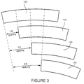
- FIG. 3 is a diagram schematically illustrating the relative positions of the marks in the four analog tracks 110, 112, 114, and 116 in the five track embodiment of the optical encoder disk shown in Figure 1, with marks 142, 144, 143, and 145 depicted for tracks 110, 112, 114, and 116, respectively.
- One particular embodiment of the first digital track involves an implementation using a base 5 numbering system to indicate the absolute position and the direction of rotation of the disk.
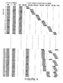
- the start symbol and encoded number for the first 20 and last 20 sectors of an exemplary base 5 encoding scheme are depicted schematically in Figure 4.
- the technique for accomplishing this requires two or more tracks of data, i.e., one digital track and one or more analog tracks, with N tracks implying the use of a base N number system.
- the absolute position data must be readable for either direction of rotation and must include a unique "start symbol" to unambiguously determine the starting point of the digital information recorded on the digital track in each sector.
- the symbol '0' is represented by a missing mark symbol '1' by a mark which is aligned with the marks in the first analog track (shown in Figure 4 as a cross-hatched rectangle in the leftmost position within a digit column), '2' by a mark which is aligned with the marks in the second analog track (in Figure 4, a rectangle shifted one position to the right within a digit column with respect to the position of a '1' symbol), '3' by a mark which is aligned with the marks in the third analog track (in Figure 4, a rectangle shifted two positions to the right within a digit column with respect to the position of a '1' symbol), and '4' by a mark which is aligned with the marks in the fourth analog track (in Figure 4, a rectangle shifted three position to the right within a digit column with respect to the position of a '1' symbol).
- the sequence '1' (in Figure 4, represented in each sector row by the left two cross-hatched rectangular marks) is designated as the start symbol. Seven of the remaining base 5 marks in each sector are then used to encode 1,000 unique numbers.
- the CD technology imposes an additional constraint, which permits no two marks to be closer than the minimum spacing. This prevents, for example, a '5' being followed by a '1' (there is some flexibility in this limitation, depending on the length chosen for each mark and the number of tracks employed, since the space between marks increases as tracks are placed radially further from the center of the encoder).
- the start symbol '1' may never occur in any number, to avoid confusion with the start symbol.
- a set of numbers for a particular embodiment of this coding scheme can be readily generated by one skilled in the art using the requirements and limitations discussed above.
- the achievable resolution in the exemplary embodiment is doubled to one part in 20,000.
- quadrature interpolation can be utilized to further increase the resolution to one part in 40,000.
- quadrature interpolation requires only four additional bits of accuracy and is therefore easily realizable using an ordinary microprocessor or logic circuit.
- a mark is provided for each 45° of phase change in the analog series. This is equivalent (in an embodiment having ten marks per analog track per sector) to providing forty analog marks per angular sector.
- the raw resolution with the additional information provided by the employment of the four analog tracks 110-116 is increased to one part in 40,000. Again, digital interpolation of the raw information can be accomplished to yield a factor of four multiplication, resulting in an accuracy in the illustrative embodiment of one part in 160,000.
- Each of the tracks namely the digital track 104 and the four analog tracks 110-116, requires a channel for optical addressing.
- the optical channels associated with the four analog tracks in essence require only four additional bits for the final accuracy figure. Encoding is therefore accomplished with one track, the digital track 104, for an absolute digital resolution of 1,000 parts per revolution, while one, two, or four analog tracks provide incremental position information relative to the last sector position and four bit digital interpolation of the analog tracks provides the final resolving power.
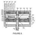
- Figure 5 is a cross sectional view of an encoder assembly using the encoder disk of Figures 1 and 2.
- first and second annular low friction coatings 146 and 148 have been applied to the surface of the encoder disk 102.
- a housing 150 encases the encoder and provides other structure necessary to allow angular displacement to be accurately determined despite wobble and despite a thermally harsh operating environment.
- the housing 150 contains an aperture at one end for rotatably admitting an encoder shaft 152 into the interior.
- the encoder shaft is attached to the encoder disk 102 so that both the encoder shaft and the encoder disk rotate together.
- the read head disk 154 carries a pair of skids 156 and 158 which are preferably made of a fluorocarbon material or coated with a fluorocarbon coating such as Teflon®.
- the skid 156 evenly opposes the low friction coating 146, while the skid 158 evenly opposes the low friction coating 148.
- the read head disk 154 is secured by a shaft 160.
- a cover 162 is rigidly attached to the housing 150 and is removable from the housing to provide service and maintenance access thereto. The inside of the cover 162 is partially packed with a filler material 164 which serves to provide additional support for the shaft 160.
- the shaft 160 is rigidly connected to the cover 162 and the read head disk 154 to prevent rotation of the read head disk.
- a compression spring 166 surrounds the shaft 160 between the filler material 164 and the read head disk 154 to urge the read head disk toward the encoder disk 102.
- This biasing of the read head disk brings the skids 156 and 158 into direct sliding contact with the low friction coatings 146 and 148 on the encoder disk.
- the read head could be mounted on the back side of the encoder disk to simplify the design.
- the shape of the marks in the digital and analog tracks can be chosen to minimize the sensitivity of the design to in-plane wobble of the encoder disk.
- a series of first collimating transfer optics 168, 170, 172, 174, and 176 are located in the read head disk 154. These elements are an array of optical fibers with appropriate focusing optics or alternatively are a series of gradient index (GRIN) lens rods. Each one of the first collimating transfer optics is positioned over a single track of the encoder disk 102. In the cover 162 and opposing the first collimating transfer optics is a set of second collimating transfer optics 178, 180, 182, 184, and 186 mounted within the filler material 164. Each element in the second collimating transfer optics is aligned with a corresponding element in the series of first collimating transfer optics.
- GRIN gradient index
- a series of five optical fibers 188, 190, 192, 194, and 196 extend from a distant point with respect to the rotary encoder assembly to connect with corresponding elements in the second series of collimating transfer optics.
- a single optic channel or connection is made between each fiber in the set of optical fibers 188-196 and thereby to each of the five tracks of the encoder disk 102, namely the digital track 104 and the four analog tracks 110, 112, 114, and 116.
- the mechanical construction of the rotary encoder assembly 150 enables the read head disk to follow the encoder disk in the event that the encoder disk develops wobble.
- the limited support which the read head disk receives near its concentric center allows any such wobble forces to be effectively transmitted into a following motion.
- the depth of field of the optical elements 178-186 is sufficiently long, the read head disk 154 and its associated collimating optics 168-176 will not be required.
- the optical fibers 188-196 can be held in close proximity to the encoder disk 102, no focussing optical elements will be needed. In the latter implementation, however, precision alignment is required. This alignment may be provided, for example, by etched grooves in a silicon or other substrate, which can be accomplished by chemical or mechanical ruling or machining.
- FIG. 6 a schematic diagram of the hybrid digital analog system of the present invention is shown incorporating the rotary encoder assembly of Figure 5.
- the set of optical fibers 188-196 shown in Figure 5 extends from the rotary encoder assembly 150 to a series of fiber optic couplers 198, 200, 202, 204, and 206.
- These fiber optic couplers are typically three port devices which allow light to be introduced into a first port for transmission out of a second port. Light returning to the second port is redirected to a third port. In this manner, a laser or other light source can be introduced at the first port to be routed through the second port to a remote location. Light returning to the second port is directed to the third port rather than back to the source, to better enable the returning light to be measured and detected without interference from the source.
- the first ports of the fiber optic couplers are connected to a light source in the form of a laser 208.
- a fanning or dispersion coupler 210 is utilized to couple light from the laser into each of the first ports of the fiber optic couplers 198-206.
- a single laser is configured to supply light in the same manner as would five separate lasers.
- an optical isolator may be necessary to prevent feedback to the laser 208 and the resulting instability in the signal level.
- a light emitting diode or other incoherent light source would not require an isolator.
- the third ports of the fiber optic couplers are each individually connected to a series of photosensitive detectors 212, 214, 216, 218, and 220 by means of a series of optical fibers 222, 224, 226, 228, and 230.
- the detectors convert the optical signals from the second ports of the fiber optic couplers into electrical signals.
- a signal processing and decoding device 232 is electrically connected to the detectors 212-220.
- the signal processing and decoding device is typically a computer, a microprocessor, or digital logic which is programmed to read, interpret, and output the digital signals it has received from the detectors.
- the second ports of the fiber optic couplers 198-206 are connected to the optical fibers 188-196 both to transmit light to, and receive digital signals from, the rotary encoder assembly 150.
- optical coupling could also be achieved with an alternative arrangement which allows the three port fiber optic couplers to be eliminated and delivers the laser light to the encoder assembly through separate illumination fibers.
- the light reflected from the disk is collection in this scheme by a set of collection fibers which are directly connected to the detectors for each track.
- this approach may provide a lower cost option by eliminating the fiber optic couplers.
- the operation of the high resolution optical hybrid digital-analog position encoder of the present invention is as follows.
- Light from the laser 208 is directed into the fiber optic couplers 198-206.
- This light propagates from the second ports of the optic couplers along the optical fibers 188-196 and into the second collimating transfer optics 178-186, where the cross sectional area in which the light is propagating is somewhat expanded. This expansion of the cross sectional area facilitates the transmission and reduces the losses of the light as it propagates between the first collimating transfer optics 168-176 and the second collimating transfer optics 178-186.
- optical fibers 188-196 should preferably be single mode fiber to preserve the interferometric effect caused by reflection of light from the pits and the surrounding surface. Multimode fiber will scramble and degrade the interference signal over the length of the fiber.
- the light propagates across the gap and into the first collimating transfer optics 168-176, from which it is positioned to focus upon the particular track on the encoder disk with which it is associated. Consequently, the first collimating transfer optics contain focussing optics on the side facing the encoder disk to efficiently direct light to the encoder disk and collect the reflected light.
- the second collimating transfer optics are designed to match the numerical aperture of the set of optical fibers 188-196.
- the first collimating transfer optics 168-176 act both to focus the downward traveling input beams on the encoder disk and to capture the beams reflecting from the surface of the encoder disk.
- the focal spot size on the encoder disk must be chosen for tolerance to fluctuations in the position of the encoder disk with respect to the read head disk and lateral tolerance due to circular shifts resulting from wobble.
- the focussing function could also be accomplished by miniature binary optic lenses, by "lensing" the ends of rods, or by using gradient index (GRIN) lenses of the correct pitch to focus light on the encoder disk and collect the reflected signals.
- GRIN gradient index
- the encoder shaft 152 turns along with the machinery to which it is connected, also rotating the encoder disk 102. Reflections from the encoder disk occur in the manner as described above for the dark bits, bright bits, and analog marks on the encoder disk. Since the read head disk 154 is slidably engaged with the encoder disk, any wobbling of the encoder disk will cause congruent wobbling of the read head disk. Even if congruent wobbling occurs, the close contact of the read head disk against the encoder disk ensures uniformity of the gap between the encoder disk and the first collimating transfer optics 168-176. The uniformity of this gap ensures that the first collimating transfer optics will retain its focus upon each respective track of the encoder disk.
- Light reflected from each of the tracks on the surface of the encoder disk is transmitted into the associated element of the first collimating transfer optics and thence to the second collimating transfer optics 178-186.
- Light from the second collimating transfer optics is impedance matched into the optical fibers 188-196. Again, the information from each track is kept segregated from the information in the other tracks, as each track of information is guided into an associated single optical fiber.
- Light propagated through the optical fibers is routed from the second to the third ports of the couplers 198-206 and into the detectors 212-220, where the optical signals are converted to digital electrical signals. The digital electrical signals are then directed into the signal processing and decoding device 232 for further treatment.
- individual optical fibers 188-196 and individual fiber optic couplers 198-206 can be replaced by a single fiber used in conjunction with a series of wavelength division multiplex couplers.
- the use of wavelength division multiplex couplers would require that each track of the encoder disk operate on a separate wavelength. This would complicate the design somewhat, but would facilitate the use of a single fiber in place of multiple optical fibers.
- the two inner tracks are conventional, with a standard 90 degree quadrature.
- the outer track in such an embodiment can use base 3 numbering, implemented identically to that described in the five track case but with a packing density higher than that which could be achieved with a binary or grey-code scheme.
- the use of two tracks represents substantial cost reduction.
- the encoding scheme reduces to base 2 and there is no start symbol.
- no quadrature is available to determine direction. A slight modification of this scheme can provide adequate performance.
- the start symbol can be encoded as a track in phase with the incremental track.
Landscapes
- Physics & Mathematics (AREA)
- General Physics & Mathematics (AREA)
- Optical Transform (AREA)
Applications Claiming Priority (2)
| Application Number | Priority Date | Filing Date | Title |
|---|---|---|---|
| US07/907,412 US5336884A (en) | 1992-07-01 | 1992-07-01 | High resolution optical hybrid absolute incremental position encoder |
| US907412 | 1992-07-01 |
Publications (2)
| Publication Number | Publication Date |
|---|---|
| EP0577104A1 true EP0577104A1 (fr) | 1994-01-05 |
| EP0577104B1 EP0577104B1 (fr) | 1997-11-12 |
Family
ID=25424053
Family Applications (1)
| Application Number | Title | Priority Date | Filing Date |
|---|---|---|---|
| EP93110449A Expired - Lifetime EP0577104B1 (fr) | 1992-07-01 | 1993-06-30 | Codeur optique de position à haute résolution du type hybride numérique-analogue |
Country Status (4)
| Country | Link |
|---|---|
| US (2) | US5336884A (fr) |
| EP (1) | EP0577104B1 (fr) |
| JP (1) | JPH06103688A (fr) |
| DE (1) | DE69315128T2 (fr) |
Cited By (17)
| Publication number | Priority date | Publication date | Assignee | Title |
|---|---|---|---|---|
| WO1997001168A1 (fr) * | 1995-06-20 | 1997-01-09 | Rickli Andre | Dispositif de traitement numerique pour signal audio |
| EP0851214A3 (fr) * | 1996-12-17 | 2000-01-05 | Tamagawa Seiki Kabushiki Kaisha | Générateur de signaux pour un encodeur |
| EP0978708A1 (fr) * | 1998-08-01 | 2000-02-09 | Dr. Johannes Heidenhain GmbH | Codeur rotatif |
| WO2000006973A1 (fr) * | 1998-07-24 | 2000-02-10 | Bishop Innovation Pty. Limited | Codeur d'angle |
| WO2001046644A1 (fr) * | 1999-12-20 | 2001-06-28 | Erik Andersson | Dispositif de mesure de position et de mouvement |
| GB2395002A (en) * | 2002-10-22 | 2004-05-12 | Bamford Excavators Ltd | Apparatus for determining angular position of a rotatable mechanical element |
| US6759648B2 (en) | 1997-08-15 | 2004-07-06 | Bishop Innovation Limited | Sensor for sensing absolute angular position of a rotatable body |
| EP1554981A4 (fr) * | 2002-10-18 | 2006-04-05 | Matsushita Electric Industrial Co Ltd | Sonde ultrasonore |
| EP1980824A1 (fr) * | 2007-04-11 | 2008-10-15 | Mitutoyo Corporation | Codeur de type mesure de la longueur absolue de la position |
| US8292598B2 (en) | 2004-11-23 | 2012-10-23 | Entegris, Inc. | System and method for a variable home position dispense system |
| US8382444B2 (en) | 2005-12-02 | 2013-02-26 | Entegris, Inc. | System and method for monitoring operation of a pump |
| US8651823B2 (en) | 2005-11-21 | 2014-02-18 | Entegris, Inc. | System and method for a pump with reduced form factor |
| US8678775B2 (en) | 2005-12-02 | 2014-03-25 | Entegris, Inc. | System and method for position control of a mechanical piston in a pump |
| US8753097B2 (en) | 2005-11-21 | 2014-06-17 | Entegris, Inc. | Method and system for high viscosity pump |
| US8870548B2 (en) | 2005-12-02 | 2014-10-28 | Entegris, Inc. | System and method for pressure compensation in a pump |
| US9631611B2 (en) | 2006-11-30 | 2017-04-25 | Entegris, Inc. | System and method for operation of a pump |
| CN112923957A (zh) * | 2019-12-06 | 2021-06-08 | 合肥欣奕华智能机器有限公司 | 伺服驱动器与编码器的信号处理方法及装置 |
Families Citing this family (31)
| Publication number | Priority date | Publication date | Assignee | Title |
|---|---|---|---|---|
| US5418362A (en) * | 1993-05-27 | 1995-05-23 | Lusby; Brett L. | Encoder for determining absolute linear and rotational positions |
| JP3412897B2 (ja) * | 1994-02-18 | 2003-06-03 | 三菱電機株式会社 | アブソリュートエンコーダ |
| JP3437277B2 (ja) * | 1994-08-01 | 2003-08-18 | キヤノン株式会社 | 回転情報検出装置及び回転情報検出方法 |
| DE69516476T2 (de) * | 1994-09-30 | 2001-02-01 | Kabushiki Kaisha Toshiba, Kawasaki | Optische Drehkodiereinrichtung und ein damit versehenes Gerät |
| AU6681196A (en) * | 1995-07-25 | 1997-02-26 | Regents Of The University Of California, The | Compact disc based high-precision optical shaft encoder |
| DE19530904B4 (de) * | 1995-08-23 | 2005-08-04 | Siemens Ag | Vorrichtung zur Erfassung einer Position eines sich relativ zu einer Basis rotatorisch oder translatorisch bewegenden Objektes |
| US5825307A (en) * | 1997-02-05 | 1998-10-20 | Perception Incorporated | Absolute linear encoder and method of production utilizing index and counter channels |
| US6081339A (en) | 1997-05-29 | 2000-06-27 | Aim Controls, Inc. | Method and apparatus for measuring the direction and position of rotating bodies |
| US6124589A (en) * | 1997-06-16 | 2000-09-26 | West; Donald Lee | Virtual mask encoder |
| US8172546B2 (en) | 1998-11-23 | 2012-05-08 | Entegris, Inc. | System and method for correcting for pressure variations using a motor |
| DE29908796U1 (de) * | 1999-05-19 | 1999-08-05 | Max Stegmann GmbH Antriebstechnik-Elektronik, 78166 Donaueschingen | Drehgeber |
| US6666375B1 (en) * | 2000-04-05 | 2003-12-23 | Hewlett-Packard Development Company, L.P. | Rotary encoders |
| US7166833B2 (en) * | 2003-10-10 | 2007-01-23 | Optelecom-Nkf | Fiber optic remote reading encoder |
| US20070114370A1 (en) * | 2003-10-10 | 2007-05-24 | Smith Ronald H | Fiber optic remote reading encoder |
| DE102004055745A1 (de) * | 2004-11-18 | 2006-06-01 | Krones Ag | Drehwertgeber und Rundläufermaschine |
| US20060187573A1 (en) * | 2005-02-24 | 2006-08-24 | Electro-Sensors, Inc. | Sensor equipment guard |
| JP5339915B2 (ja) * | 2005-11-21 | 2013-11-13 | インテグリス・インコーポレーテッド | ポンプの機械式ピストンのピストン制御システムおよび方法 |
| US7507950B2 (en) * | 2006-11-09 | 2009-03-24 | Avago Technologies Ecbu Ip (Singapore) Pte. Ltd. | Encoder with a combined position and index track |
| TWI471531B (zh) * | 2008-08-26 | 2015-02-01 | 尼康股份有限公司 | Encoder system, signal processing method |
| US7875844B2 (en) * | 2008-09-02 | 2011-01-25 | Delta Electronics, Inc. | Absolute-type encoder and method for detecting absolute position |
| US8842028B2 (en) * | 2009-02-16 | 2014-09-23 | Telefonaktiebolaget L M Ericsson (Publ) | Optical digital-to-analog converstion |
| JP4945674B2 (ja) * | 2010-11-08 | 2012-06-06 | 株式会社安川電機 | 反射型エンコーダ、サーボモータ及びサーボユニット |
| WO2014049661A1 (fr) * | 2012-09-27 | 2014-04-03 | テルモ株式会社 | Pompe à perfusion |
| US10119842B1 (en) * | 2014-08-05 | 2018-11-06 | X Development Llc | Encoder design and use |
| US10502593B1 (en) * | 2018-06-07 | 2019-12-10 | Philip M. Johnson | Linear and rotary multitrack absolute position encoder and methods using the same |
| DE102018212788A1 (de) | 2018-07-31 | 2020-02-06 | Hiwin Mikrosystem Corp. | Optische Positionsmessvorrichtung |
| TWI659196B (zh) | 2018-11-02 | 2019-05-11 | 國立交通大學 | 光學編碼裝置 |
| CN211346681U (zh) | 2020-02-17 | 2020-08-25 | 江苏多维科技有限公司 | 一种直线位移绝对位置编码器 |
| FR3111979B1 (fr) * | 2020-06-30 | 2023-03-24 | Codechamp | Revetement reflechissant des moyens de reflexion d’un codeur optique et codeur optique ainsi realise |
| JP7674993B2 (ja) | 2020-11-25 | 2025-05-12 | ドクトル・ヨハネス・ハイデンハイン・ゲゼルシヤフト・ミツト・ベシユレンクテル・ハフツング | 光学式位置測定装置 |
| KR20220117495A (ko) * | 2021-02-17 | 2022-08-24 | 삼성전기주식회사 | 회전체 장치 및 회전체 각위치 검출 장치 |
Citations (6)
| Publication number | Priority date | Publication date | Assignee | Title |
|---|---|---|---|---|
| DE3102125A1 (de) * | 1981-01-23 | 1982-08-05 | Dr. Johannes Heidenhain Gmbh, 8225 Traunreut | Inkrementale laengen- oder winkelmesseinrichtung |
| DE3337653A1 (de) * | 1983-10-17 | 1985-05-02 | Dr. Johannes Heidenhain Gmbh, 8225 Traunreut | Verfahren zur signaluebertragung und einrichtung zur durchfuehrung des verfahrens |
| EP0172323A1 (fr) * | 1984-07-25 | 1986-02-26 | Dr. Johannes Heidenhain GmbH | Appareil de mesure |
| US5003171A (en) * | 1990-01-26 | 1991-03-26 | Allied Signal Inc. | Optical encoding arrangement for absolute angle measurements |
| DE4028792A1 (de) * | 1989-09-12 | 1991-03-28 | Optec D D Melco Lab Co | Codierter winkelgeber |
| DE4025055A1 (de) * | 1990-08-07 | 1992-02-13 | Base Ten Systems Electronics G | Positionsauslesevorrichtung, insbesondere fuer maschinen- und drehtisch-steuerungen |
Family Cites Families (7)
| Publication number | Priority date | Publication date | Assignee | Title |
|---|---|---|---|---|
| US3058001A (en) * | 1960-04-21 | 1962-10-09 | Baldwin Piano Co | Photoelectric encoder |
| US3982106A (en) * | 1973-05-14 | 1976-09-21 | Contraves Ag | System for measuring the longitudinal or angular displacement of a movable component |
| JPS5829093A (ja) * | 1981-08-13 | 1983-02-21 | 株式会社トプコン | アブソリユ−トエンコ−ダ |
| US4633224A (en) * | 1985-05-06 | 1986-12-30 | Caterpillar Inc. | Absolute and incremental optical encoder |
| US4914437A (en) * | 1986-12-04 | 1990-04-03 | Regents Of The University Of California | Encoder for measuring both incremental and absolute positions of moving elements |
| US5068529A (en) * | 1988-12-22 | 1991-11-26 | Nikon Corporation | Absolute position detection encoder |
| US5073711A (en) * | 1990-09-17 | 1991-12-17 | The United States Of America As Represented By The Secretary Of The Navy | Fiber-optic remote angular position sensor including a polarization track |
-
1992
- 1992-07-01 US US07/907,412 patent/US5336884A/en not_active Expired - Lifetime
-
1993
- 1993-06-29 JP JP5158583A patent/JPH06103688A/ja active Pending
- 1993-06-30 DE DE69315128T patent/DE69315128T2/de not_active Expired - Lifetime
- 1993-06-30 EP EP93110449A patent/EP0577104B1/fr not_active Expired - Lifetime
- 1993-12-17 US US08/169,474 patent/US5451776A/en not_active Expired - Lifetime
Patent Citations (6)
| Publication number | Priority date | Publication date | Assignee | Title |
|---|---|---|---|---|
| DE3102125A1 (de) * | 1981-01-23 | 1982-08-05 | Dr. Johannes Heidenhain Gmbh, 8225 Traunreut | Inkrementale laengen- oder winkelmesseinrichtung |
| DE3337653A1 (de) * | 1983-10-17 | 1985-05-02 | Dr. Johannes Heidenhain Gmbh, 8225 Traunreut | Verfahren zur signaluebertragung und einrichtung zur durchfuehrung des verfahrens |
| EP0172323A1 (fr) * | 1984-07-25 | 1986-02-26 | Dr. Johannes Heidenhain GmbH | Appareil de mesure |
| DE4028792A1 (de) * | 1989-09-12 | 1991-03-28 | Optec D D Melco Lab Co | Codierter winkelgeber |
| US5003171A (en) * | 1990-01-26 | 1991-03-26 | Allied Signal Inc. | Optical encoding arrangement for absolute angle measurements |
| DE4025055A1 (de) * | 1990-08-07 | 1992-02-13 | Base Ten Systems Electronics G | Positionsauslesevorrichtung, insbesondere fuer maschinen- und drehtisch-steuerungen |
Cited By (28)
| Publication number | Priority date | Publication date | Assignee | Title |
|---|---|---|---|---|
| WO1997001168A1 (fr) * | 1995-06-20 | 1997-01-09 | Rickli Andre | Dispositif de traitement numerique pour signal audio |
| EP0851214A3 (fr) * | 1996-12-17 | 2000-01-05 | Tamagawa Seiki Kabushiki Kaisha | Générateur de signaux pour un encodeur |
| US6759648B2 (en) | 1997-08-15 | 2004-07-06 | Bishop Innovation Limited | Sensor for sensing absolute angular position of a rotatable body |
| WO2000006973A1 (fr) * | 1998-07-24 | 2000-02-10 | Bishop Innovation Pty. Limited | Codeur d'angle |
| US6885457B1 (en) | 1998-08-01 | 2005-04-26 | Dr. Johannes Heidenhein Gmbh | Rotary position measuring system |
| EP0978708A1 (fr) * | 1998-08-01 | 2000-02-09 | Dr. Johannes Heidenhain GmbH | Codeur rotatif |
| WO2001046644A1 (fr) * | 1999-12-20 | 2001-06-28 | Erik Andersson | Dispositif de mesure de position et de mouvement |
| EP1554981A4 (fr) * | 2002-10-18 | 2006-04-05 | Matsushita Electric Industrial Co Ltd | Sonde ultrasonore |
| US7431697B2 (en) | 2002-10-18 | 2008-10-07 | Matsushita Electric Industrial Co., Ltd. | Ultrasonic probe |
| GB2395002A (en) * | 2002-10-22 | 2004-05-12 | Bamford Excavators Ltd | Apparatus for determining angular position of a rotatable mechanical element |
| US9617988B2 (en) | 2004-11-23 | 2017-04-11 | Entegris, Inc. | System and method for variable dispense position |
| US8814536B2 (en) | 2004-11-23 | 2014-08-26 | Entegris, Inc. | System and method for a variable home position dispense system |
| US8292598B2 (en) | 2004-11-23 | 2012-10-23 | Entegris, Inc. | System and method for a variable home position dispense system |
| US8753097B2 (en) | 2005-11-21 | 2014-06-17 | Entegris, Inc. | Method and system for high viscosity pump |
| US9399989B2 (en) | 2005-11-21 | 2016-07-26 | Entegris, Inc. | System and method for a pump with onboard electronics |
| US8651823B2 (en) | 2005-11-21 | 2014-02-18 | Entegris, Inc. | System and method for a pump with reduced form factor |
| US8382444B2 (en) | 2005-12-02 | 2013-02-26 | Entegris, Inc. | System and method for monitoring operation of a pump |
| US8678775B2 (en) | 2005-12-02 | 2014-03-25 | Entegris, Inc. | System and method for position control of a mechanical piston in a pump |
| US8662859B2 (en) | 2005-12-02 | 2014-03-04 | Entegris, Inc. | System and method for monitoring operation of a pump |
| US8870548B2 (en) | 2005-12-02 | 2014-10-28 | Entegris, Inc. | System and method for pressure compensation in a pump |
| US9309872B2 (en) | 2005-12-02 | 2016-04-12 | Entegris, Inc. | System and method for position control of a mechanical piston in a pump |
| US9816502B2 (en) | 2005-12-02 | 2017-11-14 | Entegris, Inc. | System and method for pressure compensation in a pump |
| US9631611B2 (en) | 2006-11-30 | 2017-04-25 | Entegris, Inc. | System and method for operation of a pump |
| CN101368831B (zh) * | 2007-04-11 | 2011-12-07 | 三丰株式会社 | 绝对位置长度测量型编码器 |
| US7825368B2 (en) | 2007-04-11 | 2010-11-02 | Mitutoyo Corporation | Absolute position length-measurement type encoder |
| EP1980824A1 (fr) * | 2007-04-11 | 2008-10-15 | Mitutoyo Corporation | Codeur de type mesure de la longueur absolue de la position |
| CN112923957A (zh) * | 2019-12-06 | 2021-06-08 | 合肥欣奕华智能机器有限公司 | 伺服驱动器与编码器的信号处理方法及装置 |
| CN112923957B (zh) * | 2019-12-06 | 2022-05-20 | 合肥欣奕华智能机器股份有限公司 | 伺服驱动器与编码器的信号处理方法及装置 |
Also Published As
| Publication number | Publication date |
|---|---|
| DE69315128T2 (de) | 1998-03-05 |
| EP0577104B1 (fr) | 1997-11-12 |
| US5336884A (en) | 1994-08-09 |
| US5451776A (en) | 1995-09-19 |
| JPH06103688A (ja) | 1994-04-15 |
| DE69315128D1 (de) | 1997-12-18 |
Similar Documents
| Publication | Publication Date | Title |
|---|---|---|
| US5336884A (en) | High resolution optical hybrid absolute incremental position encoder | |
| US5107107A (en) | Laser optical disk position encoder with active heads | |
| US4602242A (en) | Encoder for photoelectric measuring devices | |
| US4746792A (en) | Optical transducer element and displacement meter comprising such an element | |
| EP0628791B1 (fr) | Appareil et grille pour détecter des rotations | |
| JPS5990013A (ja) | 位置検出装置 | |
| US4870559A (en) | Intelligent transducer | |
| JPS63234729A (ja) | 位置検出装置 | |
| US11448529B2 (en) | Optical rotary encoder | |
| US20220221311A1 (en) | Rotary position encoder based on polarization | |
| US7842913B2 (en) | Method for determining the position of a first moving component relative to a second component and device for applying said method | |
| US5602388A (en) | Absolute and directional encoder using optical disk | |
| US20110139971A1 (en) | Rotary position encoder | |
| CN1020956C (zh) | 绝对式轴角编码器设计方法及编码器 | |
| US7538312B2 (en) | Method for determining the position of a first moving component relatively to a second component and device for applying said method | |
| US8093546B2 (en) | Out-of-round coder | |
| JP2537146B2 (ja) | 変位測定装置 | |
| US5042157A (en) | Fiber optic angular orientation sensor digital serial encoding | |
| WO1997005456A1 (fr) | Codeur optique de position angulaire haute precision, a disque compact | |
| EP0592088A1 (fr) | Dispositif de codage | |
| US6919559B2 (en) | High-temperature optical rotary and linear position sensor | |
| SU1056243A1 (ru) | Фотоэлектрический преобразователь угла поворота вала в код | |
| JPH08271287A (ja) | 変位情報検出装置及びこれを用いたドライブ制御装置及びスケール装置 | |
| EP0246892A2 (fr) | Transducteur optique de position | |
| JPH02231524A (ja) | ロータリーエンコーダ |
Legal Events
| Date | Code | Title | Description |
|---|---|---|---|
| PUAI | Public reference made under article 153(3) epc to a published international application that has entered the european phase |
Free format text: ORIGINAL CODE: 0009012 |
|
| AK | Designated contracting states |
Kind code of ref document: A1 Designated state(s): DE FR GB |
|
| 17P | Request for examination filed |
Effective date: 19940628 |
|
| 17Q | First examination report despatched |
Effective date: 19951215 |
|
| GRAG | Despatch of communication of intention to grant |
Free format text: ORIGINAL CODE: EPIDOS AGRA |
|
| GRAH | Despatch of communication of intention to grant a patent |
Free format text: ORIGINAL CODE: EPIDOS IGRA |
|
| GRAH | Despatch of communication of intention to grant a patent |
Free format text: ORIGINAL CODE: EPIDOS IGRA |
|
| GRAA | (expected) grant |
Free format text: ORIGINAL CODE: 0009210 |
|
| AK | Designated contracting states |
Kind code of ref document: B1 Designated state(s): DE FR GB |
|
| REF | Corresponds to: |
Ref document number: 69315128 Country of ref document: DE Date of ref document: 19971218 |
|
| ET | Fr: translation filed | ||
| PLBE | No opposition filed within time limit |
Free format text: ORIGINAL CODE: 0009261 |
|
| STAA | Information on the status of an ep patent application or granted ep patent |
Free format text: STATUS: NO OPPOSITION FILED WITHIN TIME LIMIT |
|
| 26N | No opposition filed | ||
| REG | Reference to a national code |
Ref country code: GB Ref legal event code: IF02 |
|
| PGFP | Annual fee paid to national office [announced via postgrant information from national office to epo] |
Ref country code: DE Payment date: 20120627 Year of fee payment: 20 |
|
| PGFP | Annual fee paid to national office [announced via postgrant information from national office to epo] |
Ref country code: FR Payment date: 20120705 Year of fee payment: 20 Ref country code: GB Payment date: 20120625 Year of fee payment: 20 |
|
| REG | Reference to a national code |
Ref country code: DE Ref legal event code: R071 Ref document number: 69315128 Country of ref document: DE |
|
| REG | Reference to a national code |
Ref country code: DE Ref legal event code: R071 Ref document number: 69315128 Country of ref document: DE |
|
| REG | Reference to a national code |
Ref country code: GB Ref legal event code: PE20 Expiry date: 20130629 |
|
| PG25 | Lapsed in a contracting state [announced via postgrant information from national office to epo] |
Ref country code: GB Free format text: LAPSE BECAUSE OF EXPIRATION OF PROTECTION Effective date: 20130629 |
|
| PG25 | Lapsed in a contracting state [announced via postgrant information from national office to epo] |
Ref country code: DE Free format text: LAPSE BECAUSE OF EXPIRATION OF PROTECTION Effective date: 20130702 |