EP0577169B1 - Vorrichtung zur Herstellung von Aufzeichnungsträgern - Google Patents
Vorrichtung zur Herstellung von Aufzeichnungsträgern Download PDFInfo
- Publication number
- EP0577169B1 EP0577169B1 EP93201623A EP93201623A EP0577169B1 EP 0577169 B1 EP0577169 B1 EP 0577169B1 EP 93201623 A EP93201623 A EP 93201623A EP 93201623 A EP93201623 A EP 93201623A EP 0577169 B1 EP0577169 B1 EP 0577169B1
- Authority
- EP
- European Patent Office
- Prior art keywords
- injection moulding
- holder
- moulding device
- installation
- transport means
- Prior art date
- Legal status (The legal status is an assumption and is not a legal conclusion. Google has not performed a legal analysis and makes no representation as to the accuracy of the status listed.)
- Expired - Lifetime
Links
Images
Classifications
-
- B—PERFORMING OPERATIONS; TRANSPORTING
- B29—WORKING OF PLASTICS; WORKING OF SUBSTANCES IN A PLASTIC STATE IN GENERAL
- B29C—SHAPING OR JOINING OF PLASTICS; SHAPING OF MATERIAL IN A PLASTIC STATE, NOT OTHERWISE PROVIDED FOR; AFTER-TREATMENT OF THE SHAPED PRODUCTS, e.g. REPAIRING
- B29C45/00—Injection moulding, i.e. forcing the required volume of moulding material through a nozzle into a closed mould; Apparatus therefor
- B29C45/17—Component parts, details or accessories; Auxiliary operations
-
- B—PERFORMING OPERATIONS; TRANSPORTING
- B29—WORKING OF PLASTICS; WORKING OF SUBSTANCES IN A PLASTIC STATE IN GENERAL
- B29C—SHAPING OR JOINING OF PLASTICS; SHAPING OF MATERIAL IN A PLASTIC STATE, NOT OTHERWISE PROVIDED FOR; AFTER-TREATMENT OF THE SHAPED PRODUCTS, e.g. REPAIRING
- B29C45/00—Injection moulding, i.e. forcing the required volume of moulding material through a nozzle into a closed mould; Apparatus therefor
- B29C45/03—Injection moulding apparatus
- B29C45/04—Injection moulding apparatus using movable moulds or mould halves
- B29C45/0433—Injection moulding apparatus using movable moulds or mould halves mounted on a conveyor belt or chain
-
- B—PERFORMING OPERATIONS; TRANSPORTING
- B29—WORKING OF PLASTICS; WORKING OF SUBSTANCES IN A PLASTIC STATE IN GENERAL
- B29C—SHAPING OR JOINING OF PLASTICS; SHAPING OF MATERIAL IN A PLASTIC STATE, NOT OTHERWISE PROVIDED FOR; AFTER-TREATMENT OF THE SHAPED PRODUCTS, e.g. REPAIRING
- B29C45/00—Injection moulding, i.e. forcing the required volume of moulding material through a nozzle into a closed mould; Apparatus therefor
- B29C45/17—Component parts, details or accessories; Auxiliary operations
- B29C45/1756—Handling of moulds or mould parts, e.g. mould exchanging means
-
- B—PERFORMING OPERATIONS; TRANSPORTING
- B29—WORKING OF PLASTICS; WORKING OF SUBSTANCES IN A PLASTIC STATE IN GENERAL
- B29C—SHAPING OR JOINING OF PLASTICS; SHAPING OF MATERIAL IN A PLASTIC STATE, NOT OTHERWISE PROVIDED FOR; AFTER-TREATMENT OF THE SHAPED PRODUCTS, e.g. REPAIRING
- B29C45/00—Injection moulding, i.e. forcing the required volume of moulding material through a nozzle into a closed mould; Apparatus therefor
- B29C45/17—Component parts, details or accessories; Auxiliary operations
- B29C45/1756—Handling of moulds or mould parts, e.g. mould exchanging means
- B29C2045/1758—Handling of moulds or mould parts, e.g. mould exchanging means exchanging stampers
-
- G—PHYSICS
- G11—INFORMATION STORAGE
- G11B—INFORMATION STORAGE BASED ON RELATIVE MOVEMENT BETWEEN RECORD CARRIER AND TRANSDUCER
- G11B7/00—Recording or reproducing by optical means, e.g. recording using a thermal beam of optical radiation by modifying optical properties or the physical structure, reproducing using an optical beam at lower power by sensing optical properties; Record carriers therefor
- G11B7/24—Record carriers characterised by shape, structure or physical properties, or by the selection of the material
- G11B7/26—Apparatus or processes specially adapted for the manufacture of record carriers
-
- G—PHYSICS
- G11—INFORMATION STORAGE
- G11B—INFORMATION STORAGE BASED ON RELATIVE MOVEMENT BETWEEN RECORD CARRIER AND TRANSDUCER
- G11B7/00—Recording or reproducing by optical means, e.g. recording using a thermal beam of optical radiation by modifying optical properties or the physical structure, reproducing using an optical beam at lower power by sensing optical properties; Record carriers therefor
- G11B7/24—Record carriers characterised by shape, structure or physical properties, or by the selection of the material
- G11B7/26—Apparatus or processes specially adapted for the manufacture of record carriers
- G11B7/263—Preparing and using a stamper, e.g. pressing or injection molding substrates
-
- Y—GENERAL TAGGING OF NEW TECHNOLOGICAL DEVELOPMENTS; GENERAL TAGGING OF CROSS-SECTIONAL TECHNOLOGIES SPANNING OVER SEVERAL SECTIONS OF THE IPC; TECHNICAL SUBJECTS COVERED BY FORMER USPC CROSS-REFERENCE ART COLLECTIONS [XRACs] AND DIGESTS
- Y10—TECHNICAL SUBJECTS COVERED BY FORMER USPC
- Y10S—TECHNICAL SUBJECTS COVERED BY FORMER USPC CROSS-REFERENCE ART COLLECTIONS [XRACs] AND DIGESTS
- Y10S425/00—Plastic article or earthenware shaping or treating: apparatus
- Y10S425/81—Sound record
Definitions
- the invention relates to an installation for manufacturing registration carriers, provided with an injection moulding device and with two holders supporting moulding plates, which are adjustable with respect to each other between a first position, in which said moulding plates bound a mould cavity, into which a material can be injected by means of the injection moulding device during operation, so as to form the registration carrier, and a second position, in which the moulding plates have been moved some distance apart, whilst means are provided for removing the registration carrier formed in this second position of the moulding plates.
- registration carriers is understood to mean sound and/or picture carriers, data carriers and the like, for example so-called compact discs, as well as carriers which can be processed at a later stage for storing sound, pictures or other data to be registered thereon. It will thereby be apparent to those skilled in the art that the registration carriers emanating from the installation according to the invention must generally undergo further processing operations in order to complete the registration carriers, such as for example the application of a metal film and the like.
- an injection moulding device is furthermore known provided with an upper stationary mould half and with two movable mould halves disposed at a lower level, which can alternately be positioned under the stationary mould halves and then be moved towards said stationary mould halves so as to form a closed mould cavity, into which casting material can be injected.
- the lower mould half is moved downward again, together with the product formed, and moved sideways so as to be able to remove said object from the lower mould half, whilst in the meantime the other one of the two lower mould halves is moved to a position under the stationary mould, so as to form a next product in conjunction with said stationary mould half.
- German Patent No. 1112645 furthermore describes a device, which is provided with a movable slide, which supports two moulds. Said moulds can be reciprocated by means of said slide between two devices for heating the moulds and a cooling station, in which a foil is pressed onto the previously heated mould present in the cooling station so as to form a registration carrier.
- a mould needs to be exchanged it will be necessary to put the device out of operation.
- the object of the invention is to obtain an installation of the above kind, wherein the above-described drawbacks of the installations of this kind that have been usual so far can be overcome.
- this can be achieved in that transport means are provided on either side of the injection moulding device, by means of which a holder supporting a moulding plate can be moved from a position located at some distance from the injection moulding device to a position suitable for cooperation with the injection moulding device, and/or from a position suitable for cooperation with the injection moulding device to a position located at some distance from the injection moulding device, whereby said transport means and said holders are provided with coupling means for detachably coupling said holders to said transport means.
- the injection moulding device is vertically disposed. Because of the vertical position of the injection moulding device a comparatively small floor surface is needed for the installation in comparison with the usual horizontal position of the injection moulding device, which is advantageous not only from a point of view of space, but which also makes it easier to possibly combine the installation with other devices for processing registration carriers.
- Another advantage of the vertical position of the injection moulding device is that it is possible to set up a moulding plate with a holder supporting the moulding plates horizontally in the installation, in a position suitable for operation, and also to move it in a horizontal position by way of the transport means, which makes it very simple to place the holders on the transport means or place a moulding plate on a holder.
- a further advantage is thereby that a holder located beside the vertical injection moulding device will also be readily accessible for exchanging a moulding plate.
- the registration carrier formed will take up a horizontal position and can remain behind on the lower moulding plate when, following injection moulding, the moulding plates move away from each other, without having to take measures to hold down the registration carrier.
- the registration carrier thus lying in a horizontal position can then be readily discharged from the installation.
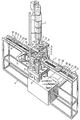
- the installation shown in the Figure comprises a frame 1, which inter alia functions to support a vertically disposed injection moulding device or extrusion device 2.
- a horizontally and fixedly disposed supporting plate 3 is provided near the bottom end of the injection moulding device 2, said supporting plate being secured to the frame by means of four columns 4.
- a holder or die plate 5, in which a moulding plate 6 is contained, is secured to the supporting plate 3.
- said moulding plate will generally be a plate which is provided with a substantially smooth surface at its bottom side, and which in principle can be used for all registration carriers to be manufactured by means of the installation.
- the installation is provided with a horizontal table 7 disposed under the supporting plate 3, extending parallel thereto, which is connected to a plate 7' disposed thereunder, which is reciprocatingly movable along the columns 4, together with the table 7, by means of a vertically disposed setting cylinder 8, as indicated by the arrow A.
- a holder or die plate 9 is supported on the table 7, said holder or die plate being provided with a circular disc-shaped projection 10, which is slightly conical in upward direction. Said disc-shaped projection functions to support a moulding plate to be placed on the disc-shaped part 10, which moulding plate, at its side remote from the disc-shaped part 10, will be provided in the usual manner with a relief for forming the desired relief in the registration carrier to be manufactured.
- the projecting part 10 By moving the holder 9 upwards by means of the table 7 and the setting cylinder 8, the projecting part 10 will be pressed into a correspondingly shaped recess in the holder 5, the two above-mentioned moulding plates bounding a moulding space, into which a suitable plastic material can be injected in the usual manner by means of the injection moulding device 2, so as to form the sound carrier.
- the table 7 can be moved downwards again and the sound carrier formed can be removed from the holder 9, for example by means of an arm 11 capable of reciprocating pivotal movement about a vertical axis, said arm at its end being provided with a suitable gripping means for taking hold of the sound carrier formed.
- the sound carrier formed can thus be pivoted into a position beside the table 7 by means of the arm 11, and then for example be discharged into a container or be delivered to a discharge conveyor or the like.
- the holder supported on the table 7 is clamped down between two jaws 13 and 14, which are movable with respect to the table 7 by way of setting means 15, in a direction towards the holder 9 and in a direction away from the holder 9.
- the frame 1 furthermore supports two conveyor belts 16 and 17, which are disposed on either side of the table 7 and which can be driven independently of each other by means of motors 18 and 19 respectively.
- the upper parts of the conveyor belts 16 and 17 lie approximately in one plane with the upper surface of said table 7.
- the motors 18 and 19 are reversible, so that objects can be moved by means of the conveyor belts 16 and 17, both in a direction towards the table 7 and in a direction away from said table 7.
- a block-shaped catch means 20 is secured to the upper part of each conveyor belt, to which catch means an arm 21 is secured, said arm extending across the upper part of the belt in question.
- Two ears 22 and 23, extending vertically upwards and constituting coupling means, are secured to the arm 21.
- the ear 23 secured to the free end of the arm 21 is provided with a slotted hole 24, which is open at the upper side of ear 23.
- the end of the rod 25 supporting the disc 26 slightly projects beyond the table 7, seen in plan view.
- the jaws 13 and 14 may be retracted by the setting means 15, so that the holder 9 will be loosely supported on the table 7.
- the motor 18 is set rotating in such a manner that, seen in the Figure, the upper part of the belt 16 moves to the left, the holder 9 with the moulding plate supported thereon will be moved from a position suitable for cooperation with the injection moulding device 2 to a position located at some distance from and beside the injection moulding device and beside the table 7, when seen in plan view.
- the holder 9 and the moulding plate supported thereon are readily accessible, so that the moulding plate supported by the holder 9 can be readily exchanged for another moulding plate.
- Said moving of the holder may take place directly, since the holder can be cooled in its position beside the injection moulding device by means of a fluid, which can be supplied to channels provided in the holder via flexible conduits connected to the holder.
- moulding plate During the production of registration carriers by means of the moulding plate supported by the holder 9, another moulding plate can be placed on a holder 27, which can be moved in a direction towards the table 7 and in a direction away from the table 7 by means of the conveyor belt 17.
- the moulding plate is again provided with a projecting arm 28 and a disc 29 acting as a stop, which is secured to the free end thereof, said disc in the position shown in the Figure being located between the two ears 22 and 23 of the catch means 20 associated with the conveyor belt 17 in question.
- the holder and the moulding plate can be brought up to a desired temperature thereby, for example by passing a fluid through channels provided in the holder, by means of flexible conduits connected to the holder, so that after the holder 27 has been placed under the injection moulding device, as described in more detail hereafter, no time is lost in heating up the holder before the installation can be put into operation again.
- this holder 27 After the holder 27 has thus been moved to a position under the injection moulding device 2, this holder will be moved upwards by means of the table 7.
- the disc-shaped part 28' of this holder which is slightly conical in upward direction, will then be pressed into the correspondingly shaped recess in the holder 5, so that an accurate centring of the holder 27 with respect to the holder 5 is effected.
- the holder 27 can be clamped down again with respect to the table 7, by clamping down the jaws 13 and 14 by way of the setting means 15. Subsequently the production process can be repeated again.
- the horizontal position of the moulding plates likewise facilitates said exchanging operation. Since also the sound carriers are manufactured in a horizontal position, removing the sound carriers can be carried out by simple means.
Landscapes
- Engineering & Computer Science (AREA)
- Manufacturing & Machinery (AREA)
- Mechanical Engineering (AREA)
- Moulds For Moulding Plastics Or The Like (AREA)
- Injection Moulding Of Plastics Or The Like (AREA)
- Liquid Crystal (AREA)
- Photographic Developing Apparatuses (AREA)
- Manufacturing Optical Record Carriers (AREA)
Claims (10)
- Vorrichtung zur Herstellung von Aufzeichnungsträgern, mit einer Spritzgußvorrichtung (2) und mit zwei Haltern (5, 9), die Formplatten tragen, die zueinander justierbar sind zwischen einer ersten Stellung, in der die Formplatten einen Formhohlraum begrenzen, in den mittels der Spritzgußvorrichtung während des Betriebes ein Material so eingespritzt werden kann, daß der Aufzeichnungsträger geformt wird, und einer zweiten Stellung, in der die Formplatten eine gewisse Entfernung auseinander bewegt wurden, wobei Einrichtungen (11) vorgesehen sind zum Entfernen des geformten Aufzeichnungsträgers in dieser zweiten Stellung der Formplatten, dadurch gekennzeichnet, daß auf jeder Seite der Spritzgußvorrichtung Transporteinrichtungen (16, 17) vorgesehen sind, durch die ein Halter (9, 27), der eine Formplatte trägt, aus einer Stellung, die sich in einer gewissen Entfernung von der Spritzgußvorrichtung (2) befindet, in eine Stellung bewegt werden kann, die zum Zusammenwirken mit der Spritzgußvorrichtung geeignet ist, und/oder aus einer Stellung, die zum Zusammenwirken mit der Spritzgußvorrichtung geeignet ist, in eine Stellung bewegt werden kann, die sich in einer gewissen Entfernung von der Spritzgußvorrichtung befindet, wobei die Transporteinrichtungen (16, 17) und die Halter (9, 27) mit Kupplungseinrichtungen (22, 23, 25, 26, 28, 29) zum lösbaren Kuppeln der Halter mit den Transporteinrichtungen versehen sind.
- Vorrichtung nach Anspruch 1, wobei die Spritzgußvorrichtung vertikal angeordnet ist.
- Vorrichtung nach Anspruch 1 oder 2, wobei eine glatte Formplatte (6) in der Vorrichtung in einer zumindest im wesentlichen horizontalen Stellung fest angeordnet ist, während eine Formplatte mit einer hinterarbeiteten Oberfläche im Inneren eines Halters (9, 27) in einer zumindest im wesentlichen horizontalen Stellung angebracht ist, wobei der Halter auf einem vertikal hin- und hergehenden Tisch (7) in einer für den Betrieb geeigneten Stellung angeordnet ist.
- Vorrichtung nach Anspruch 3, wobei die Transporteinrichtungen (16, 17) so angeordnet sind, daß Kalter (9, 27) mittels der Transporteinrichtungen auf den Tisch und von ihm herunter bewegt werden können, wenn der Tisch (7) eine unterste Stellung einnimmt.
- Vorrichtung nach einem der Ansprüche 1 bis 4, wobei die Kupplungseinrichtungen (22, 23, 25, 26, 28, 29) so gestaltet sind, daß sie je nach Bedarf durch eine vertikale Bewegung der Halter (9, 27) bezüglich der Transporteinrichtungen (16, 17) aneinandergekuppelt oder entkuppelt werden können.
- Vorrichtung nach Anspruch 5, wobei die Transporteinrichtungen (16, 17) so gestaltet sind, daß die mit den Transporteinrichtungen verbundenen Kupplungseinrichtungen (22, 23) für eine hin- und hergehende Bewegung entlang eines im wesentlichen linearen Weges geeignet sind.
- Vorrichtung nach einem der Ansprüche 1 bis 6, wobei die Transporteinrichtungen (16, 17) endlose Förderbänder sind, an denen mit den Haltern (9, 27) zu kuppelnde Mitnehmereinrichtungen (20) befestigt sind.
- Vorrichtung nach Anspruch 6, wobei eine Mitnehmereinrichtung (20) mit zwei sich aufwärts erstreckenden Laschen (22, 23) versehen ist, zwischen die ein an einem Halter (9, 27) befestigter Anschlag (26) vorgesehen werden kann.
- Vorrichtung nach einem der vorstehenden Ansprüche, wobei die Vorrichtung mit einem Arm (11) versehen ist, der um eine vertikale Achse schwenkbar ist, wobei der Arm eine Greifeinrichtung zum Entfernen eines geformten Aufzeichnungsträgers trägt.
- Vorrichtung nach Anspruch 1, wobei Einrichtungen vorgesehen sind, durch die ein Halter, der in einer gewissen Entfernung von der Spritzgußvorrichtung angeordnet ist, auf eine gewünschte Temperatur gebracht werden kann.
Applications Claiming Priority (2)
| Application Number | Priority Date | Filing Date | Title |
|---|---|---|---|
| NL9201075A NL9201075A (nl) | 1992-06-18 | 1992-06-18 | Installatie voor het vervaardigen van registratiedragers. |
| NL9201075 | 1992-06-18 |
Publications (2)
| Publication Number | Publication Date |
|---|---|
| EP0577169A1 EP0577169A1 (de) | 1994-01-05 |
| EP0577169B1 true EP0577169B1 (de) | 1996-02-21 |
Family
ID=19860941
Family Applications (1)
| Application Number | Title | Priority Date | Filing Date |
|---|---|---|---|
| EP93201623A Expired - Lifetime EP0577169B1 (de) | 1992-06-18 | 1993-06-08 | Vorrichtung zur Herstellung von Aufzeichnungsträgern |
Country Status (8)
| Country | Link |
|---|---|
| US (1) | US5451155A (de) |
| EP (1) | EP0577169B1 (de) |
| JP (1) | JPH0655567A (de) |
| KR (1) | KR100298680B1 (de) |
| CN (1) | CN1066840C (de) |
| AT (1) | ATE134336T1 (de) |
| DE (1) | DE69301584T2 (de) |
| NL (1) | NL9201075A (de) |
Families Citing this family (11)
| Publication number | Priority date | Publication date | Assignee | Title |
|---|---|---|---|---|
| US6331318B1 (en) * | 1994-09-30 | 2001-12-18 | Emisphere Technologies Inc. | Carbon-substituted diketopiperazine delivery systems |
| US5773039A (en) * | 1996-04-01 | 1998-06-30 | Jones; Earl S. | Apparatus for multiple wax castings |
| NL1002849C2 (nl) * | 1996-04-12 | 1997-10-15 | Od & Me Bv | Inrichting voor het bewerken van een schijfvormig substraat alsmede een station geschikt voor koppeling met een dergelijke inrichting. |
| US6592356B1 (en) | 1999-05-05 | 2003-07-15 | Johnson & Johnson Vision Care, Inc. | Mold, molding system and molding machine for making ophthalmic devices |
| KR20040032178A (ko) * | 2002-10-01 | 2004-04-17 | 이성래 | 회로기판의 리이드 프레임 제조방법 |
| US7320587B2 (en) * | 2005-08-09 | 2008-01-22 | Cooper Vision, Inc. | Contact lens molds and systems and methods for producing same |
| BR102013018384B1 (pt) * | 2012-08-01 | 2020-12-01 | Braun Gmbh | dispositivo de moldagem para a fabricação de pelo menos um objeto plástico injetado e método para transferir pelo menos uma segunda metade de molde para dentro, através e para fora de um dispositivo de moldagem |
| AT513291B1 (de) * | 2012-09-07 | 2015-05-15 | Engel Austria Gmbh | Vertikale Zwei-Platten-Schließeinheit, Spritzgießmaschine sowie Verfahren zur Herstellung von Hybridspritzgussteilen |
| BE1021675B1 (de) * | 2013-04-26 | 2016-01-05 | Gb Boucherie Nv | Spritzgiessvorrichtung |
| US12318981B2 (en) | 2020-06-03 | 2025-06-03 | Canon Virginia, Inc. | Conveyance apparatus for conveying mold |
| CN114368112B (zh) * | 2021-12-31 | 2024-09-20 | 天津华夏联盛汽车部件有限公司 | 一种拖车沟盖注塑模具装置 |
Family Cites Families (15)
| Publication number | Priority date | Publication date | Assignee | Title |
|---|---|---|---|---|
| US2433654A (en) * | 1944-05-04 | 1947-12-30 | Watson Stillman Co | Injection molding machine |
| DE1112645B (de) * | 1957-09-26 | 1961-08-10 | Joachim Brandenburger Fa | Verfahren zur Herstellung von Folien- oder Bildschallplatten aus thermoplastischen Kunststoffen |
| JPS605164B2 (ja) * | 1980-02-05 | 1985-02-08 | キヤニヨン株式会社 | 射出成形機 |
| DE3028947C2 (de) * | 1980-07-30 | 1983-11-17 | Polygram Gmbh, 2000 Hamburg | Verfahren zur Herstellung plattenförmiger, optisch auslesbarer Informationsträger hoher Speicherdichte |
| US4449916A (en) * | 1980-11-20 | 1984-05-22 | Matsushita Electric Industrial Co., Ltd. | Device for manufacturing information recording mediums |
| JPS58119926U (ja) * | 1982-02-04 | 1983-08-16 | 相生精機株式会社 | 金型を用いる加工機械の金型交換装置 |
| EP0092685B2 (de) * | 1982-04-26 | 1995-08-02 | Battenfeld GmbH | Schnellwechsel- und/oder Spannvorrichtung für die Formwerkzeuge von Spritzgiessmaschinen |
| JPS60256947A (ja) * | 1984-06-01 | 1985-12-18 | Hitachi Ltd | スタンパ作製方法 |
| US4581188A (en) * | 1984-09-19 | 1986-04-08 | Rca Corporation | Transfer apparatus for a molding press |
| US4737096A (en) * | 1985-07-01 | 1988-04-12 | Kanaaldijk Z.W. | Injection mould with insert piece and injection moulding unit for same |
| US4772196A (en) * | 1986-02-26 | 1988-09-20 | Kabushiki Kaisha Meiki Seisakusho | Molding apparatus for producing centrally-apertured discs |
| DE3613334A1 (de) * | 1986-04-19 | 1987-10-22 | Kloeckner Ferromatik Desma | Spritzgiessform zum spritzgiessen von informationstraegerplatten |
| US4795124A (en) * | 1986-09-18 | 1989-01-03 | The Snair Company | Extractor apparatus for removing articles from article forming machines |
| NL8701499A (nl) * | 1987-06-26 | 1989-01-16 | Philips Nv | Spuitvorminrichting voor het vervaardigen van informatieplaten uit kunststof, alsmede werkwijze voor het vervaardigen van informatieplaten uit kunststof met een spuitvorminrichting. |
| DE4008310C2 (de) * | 1990-03-15 | 1994-10-06 | Krauss Maffei Ag | Vorrichtung zum Entnehmen von Spritzgießteilen |
-
1992
- 1992-06-18 NL NL9201075A patent/NL9201075A/nl not_active Application Discontinuation
-
1993
- 1993-06-08 AT AT93201623T patent/ATE134336T1/de not_active IP Right Cessation
- 1993-06-08 EP EP93201623A patent/EP0577169B1/de not_active Expired - Lifetime
- 1993-06-08 DE DE69301584T patent/DE69301584T2/de not_active Expired - Fee Related
- 1993-06-18 US US08/077,997 patent/US5451155A/en not_active Expired - Fee Related
- 1993-06-18 KR KR1019930011187A patent/KR100298680B1/ko not_active Expired - Fee Related
- 1993-06-18 CN CN93109034A patent/CN1066840C/zh not_active Expired - Fee Related
- 1993-06-18 JP JP5147221A patent/JPH0655567A/ja active Pending
Also Published As
| Publication number | Publication date |
|---|---|
| ATE134336T1 (de) | 1996-03-15 |
| DE69301584D1 (de) | 1996-03-28 |
| NL9201075A (nl) | 1994-01-17 |
| US5451155A (en) | 1995-09-19 |
| CN1082234A (zh) | 1994-02-16 |
| DE69301584T2 (de) | 1996-08-29 |
| KR100298680B1 (ko) | 2001-10-22 |
| EP0577169A1 (de) | 1994-01-05 |
| CN1066840C (zh) | 2001-06-06 |
| JPH0655567A (ja) | 1994-03-01 |
| KR940006086A (ko) | 1994-03-23 |
Similar Documents
| Publication | Publication Date | Title |
|---|---|---|
| US5451155A (en) | Installation for manufacturing registration carriers | |
| SU1378778A3 (ru) | Приспособление дл удалени изделий с формовочного устройства | |
| US5540543A (en) | Apparatus for removing and transporting articles from molds | |
| US6814556B2 (en) | Resin molding machine and resin tablet feeding machine | |
| JPH02165922A (ja) | 射出成形装置 | |
| EP0832728A3 (de) | Verfahren und Vorrichtung zum Positionieren von Formwerkzeugen | |
| US4673022A (en) | Arrangement for the changing of implements in foundry machines | |
| RU2006115251A (ru) | Устройство кондиционирования для изделий из пластика и способ для его осуществления | |
| EP1154465B1 (de) | Vorrichtung zum Einkapseln von elektronischen Komponenten | |
| CN217047250U (zh) | 一种全自动螺母镶件注塑工装 | |
| US6530766B1 (en) | Device for manufacturing information carriers by injection moulding | |
| CN209937516U (zh) | 一种模具自动投胶机 | |
| CN223369883U (zh) | 一种嵌件埋入装置 | |
| CN217621189U (zh) | 一种浇注料生产的成型装置 | |
| JP3057639B1 (ja) | 射出成形機 | |
| CN217700221U (zh) | 废料分离机构 | |
| JP4078231B2 (ja) | 成形品収納装置及び樹脂封止装置 | |
| CN121492285A (zh) | 矽钢片自动埋取机 | |
| JP2003127189A (ja) | 射出成形機における成形品回収システム | |
| CN218019916U (zh) | 勺子转运机构 | |
| JPH038407Y2 (de) | ||
| JP2527252B2 (ja) | 中空成形金型 | |
| NL1017134C2 (nl) | Inrichting en werkwijze voor het aanvoeren van producten, in het bijzonder velvormige producten zoals in mould labels. | |
| SU1698079A1 (ru) | Устройство дл перезар дки пресс-форм к прессу | |
| JP2565600Y2 (ja) | ワーク折曲げ加工装置 |
Legal Events
| Date | Code | Title | Description |
|---|---|---|---|
| PUAI | Public reference made under article 153(3) epc to a published international application that has entered the european phase |
Free format text: ORIGINAL CODE: 0009012 |
|
| AK | Designated contracting states |
Kind code of ref document: A1 Designated state(s): AT BE CH DE DK ES FR GB GR IE IT LI LU MC NL PT SE |
|
| 17P | Request for examination filed |
Effective date: 19940120 |
|
| RAP1 | Party data changed (applicant data changed or rights of an application transferred) |
Owner name: ODME INTERNATIONAL B.V. |
|
| 17Q | First examination report despatched |
Effective date: 19950711 |
|
| RAP1 | Party data changed (applicant data changed or rights of an application transferred) |
Owner name: ODME INTERNATIONAL B.V. |
|
| GRAA | (expected) grant |
Free format text: ORIGINAL CODE: 0009210 |
|
| AK | Designated contracting states |
Kind code of ref document: B1 Designated state(s): AT BE CH DE DK ES FR GB GR IE IT LI LU MC NL PT SE |
|
| PG25 | Lapsed in a contracting state [announced via postgrant information from national office to epo] |
Ref country code: IT Free format text: LAPSE BECAUSE OF FAILURE TO SUBMIT A TRANSLATION OF THE DESCRIPTION OR TO PAY THE FEE WITHIN THE PRE;WARNING: LAPSES OF ITALIAN PATENTS WITH EFFECTIVE DATE BEFORE 2007 MAY HAVE OCCURRED AT ANY TIME BEFORE 2007. THE CORRECT EFFECTIVE DATE MAY BE DIFFERENT FROM THE ONE RECORDED.SCRIBED TIME-LIMIT Effective date: 19960221 Ref country code: GR Free format text: LAPSE BECAUSE OF FAILURE TO SUBMIT A TRANSLATION OF THE DESCRIPTION OR TO PAY THE FEE WITHIN THE PRESCRIBED TIME-LIMIT Effective date: 19960221 Ref country code: ES Free format text: THE PATENT HAS BEEN ANNULLED BY A DECISION OF A NATIONAL AUTHORITY Effective date: 19960221 Ref country code: DK Effective date: 19960221 Ref country code: BE Effective date: 19960221 Ref country code: AT Effective date: 19960221 |
|
| REF | Corresponds to: |
Ref document number: 134336 Country of ref document: AT Date of ref document: 19960315 Kind code of ref document: T |
|
| REG | Reference to a national code |
Ref country code: IE Ref legal event code: FG4D Free format text: 67304 |
|
| REF | Corresponds to: |
Ref document number: 69301584 Country of ref document: DE Date of ref document: 19960328 |
|
| ET | Fr: translation filed | ||
| REG | Reference to a national code |
Ref country code: CH Ref legal event code: NV Representative=s name: ROTTMANN, ZIMMERMANN + PARTNER AG |
|
| PG25 | Lapsed in a contracting state [announced via postgrant information from national office to epo] |
Ref country code: PT Effective date: 19960521 |
|
| PG25 | Lapsed in a contracting state [announced via postgrant information from national office to epo] |
Ref country code: IE Free format text: LAPSE BECAUSE OF NON-PAYMENT OF DUE FEES Effective date: 19960608 |
|
| PG25 | Lapsed in a contracting state [announced via postgrant information from national office to epo] |
Ref country code: MC Effective date: 19960630 Ref country code: LU Free format text: LAPSE BECAUSE OF NON-PAYMENT OF DUE FEES Effective date: 19960630 |
|
| PLBE | No opposition filed within time limit |
Free format text: ORIGINAL CODE: 0009261 |
|
| STAA | Information on the status of an ep patent application or granted ep patent |
Free format text: STATUS: NO OPPOSITION FILED WITHIN TIME LIMIT |
|
| 26N | No opposition filed | ||
| REG | Reference to a national code |
Ref country code: GB Ref legal event code: IF02 |
|
| NLS | Nl: assignments of ep-patents |
Owner name: OTB GROUP B.V. |
|
| PGFP | Annual fee paid to national office [announced via postgrant information from national office to epo] |
Ref country code: GB Payment date: 20020605 Year of fee payment: 10 |
|
| PGFP | Annual fee paid to national office [announced via postgrant information from national office to epo] |
Ref country code: SE Payment date: 20020610 Year of fee payment: 10 |
|
| PGFP | Annual fee paid to national office [announced via postgrant information from national office to epo] |
Ref country code: FR Payment date: 20020626 Year of fee payment: 10 Ref country code: CH Payment date: 20020626 Year of fee payment: 10 |
|
| REG | Reference to a national code |
Ref country code: CH Ref legal event code: PUE Owner name: OTB GROUP B.V. Free format text: ODME INTERNATIONAL B.V.#DE RUN 4315#NL-5503 LP VELDHOVEN (NL) -TRANSFER TO- OTB GROUP B.V.#LUCHTHAVENWEG 10#5657 EB EINDHOVEN (NL) Ref country code: CH Ref legal event code: NV Representative=s name: PATENTANWAELTE SCHAAD, BALASS, MENZL & PARTNER AG |
|
| PG25 | Lapsed in a contracting state [announced via postgrant information from national office to epo] |
Ref country code: GB Free format text: LAPSE BECAUSE OF NON-PAYMENT OF DUE FEES Effective date: 20030608 |
|
| PG25 | Lapsed in a contracting state [announced via postgrant information from national office to epo] |
Ref country code: SE Free format text: LAPSE BECAUSE OF NON-PAYMENT OF DUE FEES Effective date: 20030609 |
|
| PG25 | Lapsed in a contracting state [announced via postgrant information from national office to epo] |
Ref country code: LI Free format text: LAPSE BECAUSE OF NON-PAYMENT OF DUE FEES Effective date: 20030630 Ref country code: CH Free format text: LAPSE BECAUSE OF NON-PAYMENT OF DUE FEES Effective date: 20030630 |
|
| REG | Reference to a national code |
Ref country code: FR Ref legal event code: TP |
|
| REG | Reference to a national code |
Ref country code: GB Ref legal event code: 732E |
|
| GBPC | Gb: european patent ceased through non-payment of renewal fee |
Effective date: 20030608 |
|
| EUG | Se: european patent has lapsed | ||
| REG | Reference to a national code |
Ref country code: CH Ref legal event code: PL |
|
| PG25 | Lapsed in a contracting state [announced via postgrant information from national office to epo] |
Ref country code: FR Free format text: LAPSE BECAUSE OF NON-PAYMENT OF DUE FEES Effective date: 20040227 |
|
| REG | Reference to a national code |
Ref country code: FR Ref legal event code: ST |
|
| PGFP | Annual fee paid to national office [announced via postgrant information from national office to epo] |
Ref country code: NL Payment date: 20060627 Year of fee payment: 14 |
|
| PGFP | Annual fee paid to national office [announced via postgrant information from national office to epo] |
Ref country code: DE Payment date: 20060628 Year of fee payment: 14 |
|
| NLV4 | Nl: lapsed or anulled due to non-payment of the annual fee |
Effective date: 20080101 |
|
| PG25 | Lapsed in a contracting state [announced via postgrant information from national office to epo] |
Ref country code: NL Free format text: LAPSE BECAUSE OF NON-PAYMENT OF DUE FEES Effective date: 20080101 Ref country code: DE Free format text: LAPSE BECAUSE OF NON-PAYMENT OF DUE FEES Effective date: 20080101 |