EP0577307A1 - Feuille scabreuse et son procédé de réalisation - Google Patents
Feuille scabreuse et son procédé de réalisation Download PDFInfo
- Publication number
- EP0577307A1 EP0577307A1 EP93304830A EP93304830A EP0577307A1 EP 0577307 A1 EP0577307 A1 EP 0577307A1 EP 93304830 A EP93304830 A EP 93304830A EP 93304830 A EP93304830 A EP 93304830A EP 0577307 A1 EP0577307 A1 EP 0577307A1
- Authority
- EP
- European Patent Office
- Prior art keywords
- base
- perforated plate
- ground
- rugged
- pattern
- Prior art date
- Legal status (The legal status is an assumption and is not a legal conclusion. Google has not performed a legal analysis and makes no representation as to the accuracy of the status listed.)
- Granted
Links
- 238000000034 method Methods 0.000 title claims abstract description 58
- 238000004519 manufacturing process Methods 0.000 title claims abstract description 25
- 230000008569 process Effects 0.000 title claims abstract description 25
- 229920001971 elastomer Polymers 0.000 claims abstract description 81
- 239000011344 liquid material Substances 0.000 claims abstract description 81
- 239000000806 elastomer Substances 0.000 claims abstract description 78
- 238000010030 laminating Methods 0.000 claims abstract description 4
- 230000015572 biosynthetic process Effects 0.000 claims description 27
- 239000003086 colorant Substances 0.000 claims description 14
- 238000005530 etching Methods 0.000 claims description 12
- 239000007788 liquid Substances 0.000 claims description 10
- 239000003795 chemical substances by application Substances 0.000 claims description 9
- 238000003825 pressing Methods 0.000 claims description 6
- 238000003475 lamination Methods 0.000 claims description 4
- 230000001154 acute effect Effects 0.000 claims description 3
- 239000013067 intermediate product Substances 0.000 claims description 2
- 230000001747 exhibiting effect Effects 0.000 abstract description 2
- 239000010410 layer Substances 0.000 description 66
- 239000000463 material Substances 0.000 description 61
- 229920005989 resin Polymers 0.000 description 14
- 239000011347 resin Substances 0.000 description 14
- 239000004745 nonwoven fabric Substances 0.000 description 11
- 238000013461 design Methods 0.000 description 10
- 230000001965 increasing effect Effects 0.000 description 9
- 238000010276 construction Methods 0.000 description 7
- 229920003225 polyurethane elastomer Polymers 0.000 description 6
- 229920003023 plastic Polymers 0.000 description 5
- 239000004033 plastic Substances 0.000 description 5
- 238000002360 preparation method Methods 0.000 description 5
- 239000002562 thickening agent Substances 0.000 description 5
- XEEYBQQBJWHFJM-UHFFFAOYSA-N Iron Chemical compound [Fe] XEEYBQQBJWHFJM-UHFFFAOYSA-N 0.000 description 4
- 230000001070 adhesive effect Effects 0.000 description 4
- 238000005304 joining Methods 0.000 description 4
- 239000000203 mixture Substances 0.000 description 4
- VYPSYNLAJGMNEJ-UHFFFAOYSA-N Silicium dioxide Chemical compound O=[Si]=O VYPSYNLAJGMNEJ-UHFFFAOYSA-N 0.000 description 3
- 239000000853 adhesive Substances 0.000 description 3
- 239000002649 leather substitute Substances 0.000 description 3
- 239000002932 luster Substances 0.000 description 3
- 239000005060 rubber Substances 0.000 description 3
- 238000005507 spraying Methods 0.000 description 3
- 229910002012 Aerosil® Inorganic materials 0.000 description 2
- 238000005520 cutting process Methods 0.000 description 2
- 230000003247 decreasing effect Effects 0.000 description 2
- 230000006866 deterioration Effects 0.000 description 2
- 238000004049 embossing Methods 0.000 description 2
- 239000000835 fiber Substances 0.000 description 2
- 239000002657 fibrous material Substances 0.000 description 2
- 239000000945 filler Substances 0.000 description 2
- 238000010438 heat treatment Methods 0.000 description 2
- 230000006872 improvement Effects 0.000 description 2
- 229910052742 iron Inorganic materials 0.000 description 2
- 239000002184 metal Substances 0.000 description 2
- 229910052751 metal Inorganic materials 0.000 description 2
- 229920001228 polyisocyanate Polymers 0.000 description 2
- 239000005056 polyisocyanate Substances 0.000 description 2
- 229920002635 polyurethane Polymers 0.000 description 2
- 239000004814 polyurethane Substances 0.000 description 2
- 238000000926 separation method Methods 0.000 description 2
- 230000035939 shock Effects 0.000 description 2
- 239000007787 solid Substances 0.000 description 2
- 239000002904 solvent Substances 0.000 description 2
- 230000003068 static effect Effects 0.000 description 2
- 229920001187 thermosetting polymer Polymers 0.000 description 2
- XLYOFNOQVPJJNP-UHFFFAOYSA-N water Substances O XLYOFNOQVPJJNP-UHFFFAOYSA-N 0.000 description 2
- 238000009736 wetting Methods 0.000 description 2
- 229910000859 α-Fe Inorganic materials 0.000 description 2
- SPBDXSGPUHCETR-JFUDTMANSA-N 8883yp2r6d Chemical compound O1[C@@H](C)[C@H](O)[C@@H](OC)C[C@@H]1O[C@@H]1[C@@H](OC)C[C@H](O[C@@H]2C(=C/C[C@@H]3C[C@@H](C[C@@]4(O[C@@H]([C@@H](C)CC4)C(C)C)O3)OC(=O)[C@@H]3C=C(C)[C@@H](O)[C@H]4OC\C([C@@]34O)=C/C=C/[C@@H]2C)/C)O[C@H]1C.C1C[C@H](C)[C@@H]([C@@H](C)CC)O[C@@]21O[C@H](C\C=C(C)\[C@@H](O[C@@H]1O[C@@H](C)[C@H](O[C@@H]3O[C@@H](C)[C@H](O)[C@@H](OC)C3)[C@@H](OC)C1)[C@@H](C)\C=C\C=C/1[C@]3([C@H](C(=O)O4)C=C(C)[C@@H](O)[C@H]3OC\1)O)C[C@H]4C2 SPBDXSGPUHCETR-JFUDTMANSA-N 0.000 description 1
- 229910001369 Brass Inorganic materials 0.000 description 1
- JOYRKODLDBILNP-UHFFFAOYSA-N Ethyl urethane Chemical compound CCOC(N)=O JOYRKODLDBILNP-UHFFFAOYSA-N 0.000 description 1
- 239000004698 Polyethylene Substances 0.000 description 1
- 239000012790 adhesive layer Substances 0.000 description 1
- 229910045601 alloy Inorganic materials 0.000 description 1
- 239000000956 alloy Substances 0.000 description 1
- 229910000828 alnico Inorganic materials 0.000 description 1
- 230000000386 athletic effect Effects 0.000 description 1
- 239000010951 brass Substances 0.000 description 1
- KPLQYGBQNPPQGA-UHFFFAOYSA-N cobalt samarium Chemical compound [Co].[Sm] KPLQYGBQNPPQGA-UHFFFAOYSA-N 0.000 description 1
- 150000001875 compounds Chemical class 0.000 description 1
- 239000006185 dispersion Substances 0.000 description 1
- 230000002708 enhancing effect Effects 0.000 description 1
- 229920006332 epoxy adhesive Polymers 0.000 description 1
- 239000003822 epoxy resin Substances 0.000 description 1
- 239000005038 ethylene vinyl acetate Substances 0.000 description 1
- 238000002474 experimental method Methods 0.000 description 1
- 230000008014 freezing Effects 0.000 description 1
- 238000007710 freezing Methods 0.000 description 1
- 238000000227 grinding Methods 0.000 description 1
- 239000003562 lightweight material Substances 0.000 description 1
- 239000000696 magnetic material Substances 0.000 description 1
- 239000007769 metal material Substances 0.000 description 1
- 238000012986 modification Methods 0.000 description 1
- 230000004048 modification Effects 0.000 description 1
- 238000000465 moulding Methods 0.000 description 1
- 230000035699 permeability Effects 0.000 description 1
- 230000000704 physical effect Effects 0.000 description 1
- 239000002985 plastic film Substances 0.000 description 1
- 229920000647 polyepoxide Polymers 0.000 description 1
- 229920001225 polyester resin Polymers 0.000 description 1
- 239000004645 polyester resin Substances 0.000 description 1
- -1 polyethylene Polymers 0.000 description 1
- 229920000573 polyethylene Polymers 0.000 description 1
- 229920005749 polyurethane resin Polymers 0.000 description 1
- 238000012545 processing Methods 0.000 description 1
- 238000004080 punching Methods 0.000 description 1
- 229910052761 rare earth metal Inorganic materials 0.000 description 1
- 150000002910 rare earth metals Chemical group 0.000 description 1
- 230000009467 reduction Effects 0.000 description 1
- 230000002787 reinforcement Effects 0.000 description 1
- 229910000938 samarium–cobalt magnet Inorganic materials 0.000 description 1
- 238000005488 sandblasting Methods 0.000 description 1
- 229920003002 synthetic resin Polymers 0.000 description 1
- 239000000057 synthetic resin Substances 0.000 description 1
- 229920001169 thermoplastic Polymers 0.000 description 1
- 229920002803 thermoplastic polyurethane Polymers 0.000 description 1
- 229920005992 thermoplastic resin Polymers 0.000 description 1
- 239000004416 thermosoftening plastic Substances 0.000 description 1
- 239000011882 ultra-fine particle Substances 0.000 description 1
Images


Classifications
-
- B—PERFORMING OPERATIONS; TRANSPORTING
- B29—WORKING OF PLASTICS; WORKING OF SUBSTANCES IN A PLASTIC STATE IN GENERAL
- B29D—PRODUCING PARTICULAR ARTICLES FROM PLASTICS OR FROM SUBSTANCES IN A PLASTIC STATE
- B29D35/00—Producing footwear
- B29D35/12—Producing parts thereof, e.g. soles, heels, uppers, by a moulding technique
- B29D35/14—Multilayered parts
- B29D35/142—Soles
-
- A—HUMAN NECESSITIES
- A43—FOOTWEAR
- A43B—CHARACTERISTIC FEATURES OF FOOTWEAR; PARTS OF FOOTWEAR
- A43B1/00—Footwear characterised by the material
- A43B1/0027—Footwear characterised by the material made at least partially from a material having special colours
- A43B1/0036—Footwear characterised by the material made at least partially from a material having special colours with fluorescent or phosphorescent parts
-
- A—HUMAN NECESSITIES
- A43—FOOTWEAR
- A43B—CHARACTERISTIC FEATURES OF FOOTWEAR; PARTS OF FOOTWEAR
- A43B1/00—Footwear characterised by the material
- A43B1/0054—Footwear characterised by the material provided with magnets, magnetic parts or magnetic substances
-
- A—HUMAN NECESSITIES
- A43—FOOTWEAR
- A43B—CHARACTERISTIC FEATURES OF FOOTWEAR; PARTS OF FOOTWEAR
- A43B1/00—Footwear characterised by the material
- A43B1/0072—Footwear characterised by the material made at least partially of transparent or translucent materials
-
- A—HUMAN NECESSITIES
- A43—FOOTWEAR
- A43B—CHARACTERISTIC FEATURES OF FOOTWEAR; PARTS OF FOOTWEAR
- A43B13/00—Soles; Sole-and-heel integral units
- A43B13/02—Soles; Sole-and-heel integral units characterised by the material
- A43B13/12—Soles with several layers of different materials
-
- A—HUMAN NECESSITIES
- A43—FOOTWEAR
- A43B—CHARACTERISTIC FEATURES OF FOOTWEAR; PARTS OF FOOTWEAR
- A43B13/00—Soles; Sole-and-heel integral units
- A43B13/14—Soles; Sole-and-heel integral units characterised by the constructive form
- A43B13/22—Soles made slip-preventing or wear-resisting, e.g. by impregnation or spreading a wear-resisting layer
- A43B13/223—Profiled soles
-
- B—PERFORMING OPERATIONS; TRANSPORTING
- B29—WORKING OF PLASTICS; WORKING OF SUBSTANCES IN A PLASTIC STATE IN GENERAL
- B29C—SHAPING OR JOINING OF PLASTICS; SHAPING OF MATERIAL IN A PLASTIC STATE, NOT OTHERWISE PROVIDED FOR; AFTER-TREATMENT OF THE SHAPED PRODUCTS, e.g. REPAIRING
- B29C33/00—Moulds or cores; Details thereof or accessories therefor
- B29C33/30—Mounting, exchanging or centering
- B29C33/301—Modular mould systems [MMS], i.e. moulds built up by stacking mould elements, e.g. plates, blocks, rods
-
- B—PERFORMING OPERATIONS; TRANSPORTING
- B29—WORKING OF PLASTICS; WORKING OF SUBSTANCES IN A PLASTIC STATE IN GENERAL
- B29C—SHAPING OR JOINING OF PLASTICS; SHAPING OF MATERIAL IN A PLASTIC STATE, NOT OTHERWISE PROVIDED FOR; AFTER-TREATMENT OF THE SHAPED PRODUCTS, e.g. REPAIRING
- B29C33/00—Moulds or cores; Details thereof or accessories therefor
- B29C33/30—Mounting, exchanging or centering
- B29C33/32—Mounting, exchanging or centering using magnetic means
-
- B—PERFORMING OPERATIONS; TRANSPORTING
- B29—WORKING OF PLASTICS; WORKING OF SUBSTANCES IN A PLASTIC STATE IN GENERAL
- B29C—SHAPING OR JOINING OF PLASTICS; SHAPING OF MATERIAL IN A PLASTIC STATE, NOT OTHERWISE PROVIDED FOR; AFTER-TREATMENT OF THE SHAPED PRODUCTS, e.g. REPAIRING
- B29C33/00—Moulds or cores; Details thereof or accessories therefor
- B29C33/42—Moulds or cores; Details thereof or accessories therefor characterised by the shape of the moulding surface, e.g. ribs or grooves
-
- B—PERFORMING OPERATIONS; TRANSPORTING
- B29—WORKING OF PLASTICS; WORKING OF SUBSTANCES IN A PLASTIC STATE IN GENERAL
- B29C—SHAPING OR JOINING OF PLASTICS; SHAPING OF MATERIAL IN A PLASTIC STATE, NOT OTHERWISE PROVIDED FOR; AFTER-TREATMENT OF THE SHAPED PRODUCTS, e.g. REPAIRING
- B29C39/00—Shaping by casting, i.e. introducing the moulding material into a mould or between confining surfaces without significant moulding pressure; Apparatus therefor
- B29C39/02—Shaping by casting, i.e. introducing the moulding material into a mould or between confining surfaces without significant moulding pressure; Apparatus therefor for making articles of definite length, i.e. discrete articles
- B29C39/12—Making multilayered or multicoloured articles
- B29C39/123—Making multilayered articles
-
- Y—GENERAL TAGGING OF NEW TECHNOLOGICAL DEVELOPMENTS; GENERAL TAGGING OF CROSS-SECTIONAL TECHNOLOGIES SPANNING OVER SEVERAL SECTIONS OF THE IPC; TECHNICAL SUBJECTS COVERED BY FORMER USPC CROSS-REFERENCE ART COLLECTIONS [XRACs] AND DIGESTS
- Y10—TECHNICAL SUBJECTS COVERED BY FORMER USPC
- Y10T—TECHNICAL SUBJECTS COVERED BY FORMER US CLASSIFICATION
- Y10T156/00—Adhesive bonding and miscellaneous chemical manufacture
- Y10T156/10—Methods of surface bonding and/or assembly therefor
- Y10T156/1052—Methods of surface bonding and/or assembly therefor with cutting, punching, tearing or severing
- Y10T156/1056—Perforating lamina
-
- Y—GENERAL TAGGING OF NEW TECHNOLOGICAL DEVELOPMENTS; GENERAL TAGGING OF CROSS-SECTIONAL TECHNOLOGIES SPANNING OVER SEVERAL SECTIONS OF THE IPC; TECHNICAL SUBJECTS COVERED BY FORMER USPC CROSS-REFERENCE ART COLLECTIONS [XRACs] AND DIGESTS
- Y10—TECHNICAL SUBJECTS COVERED BY FORMER USPC
- Y10T—TECHNICAL SUBJECTS COVERED BY FORMER US CLASSIFICATION
- Y10T428/00—Stock material or miscellaneous articles
- Y10T428/24—Structurally defined web or sheet [e.g., overall dimension, etc.]
- Y10T428/24479—Structurally defined web or sheet [e.g., overall dimension, etc.] including variation in thickness
- Y10T428/24612—Composite web or sheet
-
- Y—GENERAL TAGGING OF NEW TECHNOLOGICAL DEVELOPMENTS; GENERAL TAGGING OF CROSS-SECTIONAL TECHNOLOGIES SPANNING OVER SEVERAL SECTIONS OF THE IPC; TECHNICAL SUBJECTS COVERED BY FORMER USPC CROSS-REFERENCE ART COLLECTIONS [XRACs] AND DIGESTS
- Y10—TECHNICAL SUBJECTS COVERED BY FORMER USPC
- Y10T—TECHNICAL SUBJECTS COVERED BY FORMER US CLASSIFICATION
- Y10T428/00—Stock material or miscellaneous articles
- Y10T428/24—Structurally defined web or sheet [e.g., overall dimension, etc.]
- Y10T428/24802—Discontinuous or differential coating, impregnation or bond [e.g., artwork, printing, retouched photograph, etc.]
- Y10T428/24851—Intermediate layer is discontinuous or differential
-
- Y—GENERAL TAGGING OF NEW TECHNOLOGICAL DEVELOPMENTS; GENERAL TAGGING OF CROSS-SECTIONAL TECHNOLOGIES SPANNING OVER SEVERAL SECTIONS OF THE IPC; TECHNICAL SUBJECTS COVERED BY FORMER USPC CROSS-REFERENCE ART COLLECTIONS [XRACs] AND DIGESTS
- Y10—TECHNICAL SUBJECTS COVERED BY FORMER USPC
- Y10T—TECHNICAL SUBJECTS COVERED BY FORMER US CLASSIFICATION
- Y10T428/00—Stock material or miscellaneous articles
- Y10T428/24—Structurally defined web or sheet [e.g., overall dimension, etc.]
- Y10T428/24802—Discontinuous or differential coating, impregnation or bond [e.g., artwork, printing, retouched photograph, etc.]
- Y10T428/24893—Discontinuous or differential coating, impregnation or bond [e.g., artwork, printing, retouched photograph, etc.] including particulate material
- Y10T428/24901—Discontinuous or differential coating, impregnation or bond [e.g., artwork, printing, retouched photograph, etc.] including particulate material including coloring matter
Definitions
- This invention relates a sheet formed into a rugged shape (hereinafter referred to as "rugged shaped sheet”) and a process for manufacturing the same, and more particularly to a rugged shaped sheet improved in non-slip and aesthetic properties and a process for manufacturing the same.
- sneakers or sports shoes used as jogging shoes, basket shoes, tennis shoes or the like are constructed into a multi-layer structure by forming an outer sole which is a lowermost layer of a shoe sole contacted with the ground or a floor of a solid rubber material or a high-density sponge material and laminating at least one sponge sheet of a light-weight material exhibiting satisfactory cushioning properties such as ethylene vinyl acetate (EVA) on the outer sole, to thereby accomplish a decrease in weight and an improvement in shock absorbing properties.
- EVA ethylene vinyl acetate
- the solid rubber or high-density sponge is relatively rigid and exhibits satisfactory ground catching properties and wear-resistant properties; however, it is increased in weight, to thereby fail to reduce the weight of the shoes.
- Another method which is likewise proposed comprises the steps of arranging a perforated plate on a nonwoven fabric material to keep both intimately contacted with each other, pouring a polyurethane elastomer material containing a thickening agent into the perforated plate, carrying out a squeezing treatment with respect to the elastomer and heating the elastomer to cure it, resulting in forming an embossed sheet.
- the method is entitled a method for manufacturing en embossed sheet and disclosed in Japanese Patent Application Laid-Open Publication No. 185822/1992 by the assignee.
- a rugged pattern formed on a sole of sports shoes is generally made of the same material as the sole in a manner to be integral with the sole. It is often desired to locally vary properties of the rugged pattern in order to enhance the non-slip properties and aesthetic properties of the sole. However, the above-described formation of the rugged pattern integral with the sole fails to significantly vary the properties of the rugged pattern.
- the present invention has been made in view of the foregoing disadvantage of the prior art.
- a rugged shaped sheet in accordance with one aspect of the present invention, includes a base sheet member and a rugged pattern of a predetermined shape adhered to the base sheet member.
- the rugged pattern comprises a combination of a plurality of pattern elements which are formed so as to be different in at least one of size, configuration and properties from each other.
- the rugged shaped sheet is used to constitute an outer sole which forms a lowermost layer of a shoe sole.
- the rugged pattern has a ground surface generally formed into a concave shape, wherein the ground surface has a periphery formed at an acute angle with respect to a side surface of the rugged pattern.
- the pattern elements of the rugged pattern have colors applied thereto in such a manner that the colors are different between each two of the pattern elements which are arranged so as to be adjacent to each other in at least a vertical direction.
- the pattern elements of the rugged pattern are formed so as to be different in size or combination of size and configuration from each other, resulting in the rugged pattern being formed into a stepwise configuration.
- the rugged pattern is constituted by the plural pattern elements which are formed so as to be different in at least one of size, configuration and properties from each other, resulting in being constructed into a multi-layer structure.
- Such construction permits the rugged pattern to be provided thereon with a strip-like color design when different colors are applied to the pattern elements, respectively, to thereby improve aesthetic properties of the rugged shaped sheet.
- the pattern elements of the rugged pattern are formed so as to be different in size or combination of size and configuration from each other, resulting in the rugged pattern being formed into a stepwise configuration, the rugged pattern may be formed into a more complicated configuration sufficient to further improve the aesthetic properties.
- a process for manufacturing a rugged shaped sheet comprises the steps of arranging a base sheet member on a base, arranging, on the base sheet member, perforated plates formed with perforations of a predetermined shape in a pattern-like manner, pouring an elastomer liquid material into the perforations of each of the perforated plates, subjecting the elastomer liquid material to a squeegee treatment; and curing the elastomer liquid material.
- At least two such perforated plates including a base-side perforated plate and a ground-side perforated plate each formed with said perforations are provided;
- the base-side perforated plate is first arranged on the base sheet member;
- the elastomer liquid is poured in a predetermined amount into the perforation of the base-side perforated plate, subject to the squeegee treatment and then semicured, resulting in forming a base layer;
- the ground-side perforated plate is arranged on the base layer thus formed;
- the elastomer liquid material is poured in a predetermined amount into the perforations of the ground-side perforated plate, subject to the squeegee treatment and cured to a degree sufficient to permit the elastomer liquid material to be removed from the ground-side perforated plate, resulting in forming a ground layer;
- the perforated layers are removed from the cured elastomer liquid material in turn subsequent to formation of the ground layer, to thereby
- the perforated plates further includes at least one intermediate perforated plate likewise formed with perforations, wherein the intermediate perforated plate is arranged on the base layer after formation of the base layer; the elastomer liquid material is poured into the perforations of the intermediate perforated plate, subject to a squeegee treatment and semicured, resulting in forming an intermediate layer; the elastomer liquid material is also poured into, if present, at least one additional intermediate perforated plate, subject to the squeegee treatment and then semicured, to thereby form at least one intermediate layer; and the ground-side perforated plate is arranged on the intermediate layer thus formed, to thereby form the ground layer.
- a process for manufacturing a rugged shaped sheet comprises the steps of arranging, on a base, perforated plates formed with perforations of a predetermined shape in a pattern-like manner; pouring an elastomer liquid material into the perforations of each of the perforated plates, followed by a squeegee treatment; arranging a base sheet member on the perforated plates and holding the former on the latter while downwardly pressing, leading to curing of the elastomer liquid material.
- the perforated plates include at least a base-side perforated plate and a ground-side perforated plate; the ground-side perforated plate is first put on the air-permeable sheet and charged with the elastomer liquid material in a predetermined amount; the elastomer liquid material poured in the ground-side perforated plate is subject to the squeegee treatment and then semicured, leading to formation of a ground layer; and a base layer is laminated on the ground layer.
- arrangement of the ground-side perforated plate on the base is carried out by arranging the air-permeable sheet on the base, arranging the ground-side perforated plate on the air-permeable sheet after, if necessary, application of a parting agent to the base, and then arranging the ground-side perforated plate on the base.
- lamination of the base layer on the ground layer is carried out by arranging the base-side perforated plate on the ground layer at the time when the ground layer is formed and arranging the base sheet member on the base layer at the time when the elastomer liquid material is semicured to form the base layer.
- lamination of the base layer on the ground layer further includes arrangement of an intermediate product formed by laminating an additional base layer on an additional base sheet member in a different step on the ground layer at the time when the ground layer is formed.
- the perforated plates further include at least one intermediate perforated plate likewise formed with perforations, wherein the intermediate perforated plate is arranged on the ground layer after formation of the ground layer; the elastomer liquid material is poured into the perforations of the intermediate perforated plate, subject to a squeegee treatment and semicured, resulting in forming an intermediate layer; and the base-side perforated plate is arranged on the intermediate layer thus formed, to thereby form the ground layer.
- the perforations of each of the perforated plates are formed by etching.
- the rugged pattern is successively formed from the base side or ground side, so that the properties, size and/or configuration of the pattern elements may be varied.
- a rugged shaped sheet of the illustrated embodiment which is generally designated at reference numeral 20 generally includes a base sheet member 22 and a rugged pattern 24 of a predetermined shape arranged in a pattern-like manner on the the base sheet member 22 while being kept adhered to the base sheet member 22.
- the base sheet material 22 is cut into a shape in conformity to a sole of sports shoes 28 and the rugged pattern 24 is formed into a predetermined shape so as to provide the sports shoes 28 with non-slip properties.
- the rugged pattern 24 thus formed is then intimately joined or adhered to the base sheet member 22, resulting in the rugged shaped sheet 20.
- the base sheet material 22 may be made of any suitable material conventionally used for a base material of an outer sole of sports shoes, such as, for example, a synthetic resin material, a rubber material, a nonwoven fabric material or the like.
- a thermoplastic fiber material or a thermosetting fiber material may be conveniently directed to this purpose.
- the nonwoven fabric material may include an artificial leather like a back skin which is sold under "ECSAINE” (Registered Trademark) from Toray Kabushiki Kaisha, Japan.
- the artificial leather may be commercially available in various kinds of colors, therefore, the shoe sole 26 may be provided with a design of any desired color contrast while applying a black color or a color similar thereto to the rugged pattern 24.
- any other suitable material such as a conventional nonwoven fabric sheet material having satisfactory peeling or tearing strength, tensile strength and resistance to wear, a film sheet material of an increased thickness, or the like may be conveniently used for this purpose.
- the material may have adhesive properties or be coated with a resin film.
- the conventional nonwoven fabric material which is conveniently used may include a nonwoven fabric material having elastic long fibers such as urethane or the like bonded thereto by autohesion. In this instance, application of a nonwoven fabric sheet having a thickness as large as about 1cm permits the sole 26 to be provided with satisfactory cushioning properties.
- the rugged pattern 3 when resin cured by ultraviolet rays is used as an elastomer liquid material P (Figs. 2A and 2B) for forming the rugged pattern 3, it is also possible to print a pattern design corresponding to the rugged pattern 24 on the base sheet member 22. This permits colors of the pattern design printed on the base sheet material 10 to be visually observed by forming the rugged pattern of a transparent or semitransparent material, resulting in the shoe sole being provided with aesthetic properties different from the above.
- various kinds of color contrast may be selected between the base sheet material 22 and the pattern design printed on the base sheet material.
- black is employed for the base sheet member 22
- a bright color such as yellow, an orange color or the like is employed for ink printed on the base sheet member 22.
- employment of colors which are different in chroma, brightness, hue or any combination thereof for the base sheet member 22 and the ink for the pattern design printed on the base sheet member 22 may permit the color of the ink to be prominent relative to the color of the base sheet member 22 in color contrast between both.
- red and blue may be employed for the base sheet member 22 and the ink for this purpose, respectively.
- the rugged pattern 24 constitutes one of features of the present invention.
- the rugged pattern 24 is constructed into a multi-layer structure by laminatedly combining a plurality of pattern elements 30 formed so as to be different in at least one of a size, a configuration and properties thereof.
- a pattern element directly tightly joined to the base sheet member 22 and an uppermost pattern element will be indicated to be a base-side pattern element 30a and a ground-side pattern element 30b, respectively.
- the number of layers of the rugged pattern 24 formed by the pattern elements 30 is at least two.
- the rugged pattern 24 is constituted by the base-side pattern element 30a and ground-side pattern element 30b described above.
- the rugged pattern 24 comprises three such pattern elements 30, the elements 30 are the above-described base-side pattern element 30a and ground-side pattern element 30b, as well as one intermediate pattern element 30c interposedly located between the pattern elements 30a and 30b as shown in Fig. 7 which will be described hereinafter.
- the number of layers of the rugged pattern 24 is four or more, two or more such intermediate pattern elements 30c are arranged between the base-side pattern element 30a and the ground-side pattern element 30b.
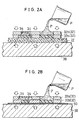
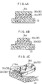
- Figs. 3A to 3C each show a rugged pattern 24 manufactured according to a first procedure in Fig. 2A wherein a base sheet member 22 is previously arranged and then perforated plates 32 are laminated on the base sheet member 22 in turn.
- the first procedure causes a squeegee-treated surface to appear on the side of a surface of the rugged pattern 24 which is contacted with the ground (hereinafter referred to as "ground surface").
- the ground surface is designated at reference character 24a.
- the ground surface 24a is formed into a gentle concave shape, so that an outer periphery of the ground surface 24a upwardly somewhat projects at an acute angle along a side surface of the pattern as shown in Figs. 3A to 3C.
- Such configuration of the rugged pattern 24 permits it to exhibit increased ground catching properties and non-slip properties.
- Figs. 4A to 4C each show a rugged pattern 24 manufactured according to a second procedure shown in Fig. 2B wherein perforated plates 32 are laminated on each other in turn and then a base sheet member 22 is set. The second procedure causes a squeegee-treated surface to appear at a joint area between pattern elements or at a joint area between the rugged pattern and the base sheet member 22.
- a ground surface 24a is rendered flat as shown in Figs. 4 A to 4 C . Nevertheless, arrangement of a breathable or air-permeable sheet 40 as described hereinafter permits the ground surface to be prevented from being contacted with the air, resulting in unnecessary luster which deteriorates texture of the sole 26 being effectively eliminated.
- the rugged patterns 24 of Figs. 3A to 3C prepared in the manner shown in Fig. 2A each are constructed by pattern elements 30 different in at least one of size, configuration and/or properties from each other, respectively.
- the pattern elements 30 constituting each of the rugged patterns 24 of Figs. 4A to 4C manufactured as shown in Figs. 2B are formed so as to be likewise different in size, configuration and/or properties from each other, respectively.
- the pattern elements 30a and 30b are applied thereto colors different from each other while being formed into the same size and configuration. More specifically, a color of the base-side pattern element 30a is rendered somewhat deep as compared with that of the ground-side pattern element 30b.
- Arrangement of colors of the pattern elements 30 is not limited to the above-described manner, so long as colors of the pattern elements 30 vertically laminated on each other are rendered different from each other. Therefore, when three or more such pattern elements 30 are provided, two kinds of colors different in hue, brightness and/or chroma may be alternately arranged to provide the pattern elements with a stripe-like design. Further, it is possible to render the pattern elements colorless or colored and transparent. Alternatively, a fluorescent color may be mixed with or substituted for the above-described colors of the pattern elements 30.
- the properties of the pattern elements 30 which may be rendered different between the pattern elements 30 may include hardness, elasticity, a shock absorbing capability, luster, satinizing and the like.
- the pattern elements 30 constituting each of the rugged patterns 24 of Figs. 3B and 4B respectively manufactured as shown in Figs. 2A and 2B are formed into sizes which are gradually decreased in turn, so that the rugged pattern 24 is formed in a stepwise manner.
- a manner in which a size of the pattern elements 30 is varied is not limited to the above so long as the perforated plates 32 can be removed from the pattern elements 30.
- the pattern elements 30 constituting each of the rugged patterns 24 of Figs. 3C and 4C respectively manufactured as shown in Figs. 2A and 2B are formed so as to be different in configuration as well as size from each other. More particularly, in the pattern elements 30 shown in each of Figs. 3C and 4C, the base-side pattern element 30a is formed into an elliptic shape in plane and the ground-side pattern element 30b is formed into a circular shape in plane and laminatedly arranged on the base-side pattern element 30a.
- a combination of size and configuration of the pattern elements 30 is not limited to the above. For example, such properties of the pattern elements 40 as shown in Figs. 3A and 4A may be incorporated in the pattern elements shown in Figs. 3C and 4C, so that the rugged pattern 24 may be widely varied in various ways. Materials for the rugged pattern 24 will be detailedly described hereinafter.
- the perforated plates 32 used in the present invention each are formed into a somewhat small thickness. This is for the reason that a plurality of the perforated plates 32 are laminatedly used for manufacturing the rugged shaped sheet; therefore, it is required to reduce a thickness of the perforated plates in view of a relationship between a height of the rugged pattern 24 and the number of perforated plates 32 and a variation in attraction force between the perforated plates 32 depending on the size and/or configuration of the rugged patterns 24 and a procedure for forming the rugged pattern 24.
- the designation "Pre-arrangement of Base Sheet Member” indicates that the base sheet member 22 is previously arranged and then the perforated plates 32 are laminated on the base sheet member 22 in order.
- the designation "Post-arrangement of Base Sheet Member” indicates that the perforated plates 32 are laminated on each other and then the base sheet member 22 is arranged. The designations are used in the same meanings throughout the specification. Therefore, the pre-arrangement of the base sheet member 22 corresponds to the procedure shown in Figs. 2A and the post-arrangement of the base sheet member 22 corresponds to the procedure shown in Fig. 2B.
- the designation "Upper Plate” indicates the perforated plate which is positioned on an upper side in each of the procedures shown in Figs. 2A and 2B and the designation “Lower Plate” indicates the perforated plate positioned on the lower side. Therefore, in the pre-arrangement of the base sheet member shown in Fig. 2A, “Upper Plate” constitutes a ground-side perforated plate 32b for forming the ground-side pattern element 30b and “Lower Plate” constitutes a base-side perforated plate 32a for forming the base-side pattern element 30a; whereas, in the post-arrangement of the base sheet member shown in Fig.
- the base-side and ground-side perforated plate 32a and 32b are prepared.
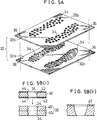
- the perforated plates 32 as shown in Fig. 5A, each are formed with perforations 34 of a predetermined shape in a predetermined pattern-like manner in conformity to a configuration of the rugged pattern 24 to be formed and its layout.
- a position of the perforations 34 is defined so as to be common to all the perforated plates 32.
- a size of the perforations of each perforated plate and a configuration thereof are determined depending on the corresponding pattern element 30 to be formed.
- a plurality of perforated plates 32 are arranged while being kept tightly contacted with each other, so that it is advantageous to increase a contact area between the perforated plates 32 as large as possible. Therefore, in the illustrated embodiment, such a rugged pattern 24 as shown in Fig. 7A which is constructed so as to reduce a difference in area between pattern elements 30 is desirable as compared with a rugged pattern 24 as shown in Fig. 7B which is constructed so as to cause a difference in area between pattern elements 30 to be rendered relatively large.
- a plurality of the perforated plates 32 are used in the illustrated embodiment, therefore, it is convenient to provide each of the perforated plates with at least one guide hole 36. Also, it is preferable to employ any means for enhancing adhesion or tightness between the perforated plates 32.
- the base 38 may comprise, for example, an electromagnetic chuck which is conventionally widely used as a workpiece holding means in a surface grinding machine.
- the perforated plates 32 to be magnetically sucked by the base 38 each may comprise a relatively thin iron plate of such a thickness as described above.
- the base may comprise a permanent magnetic chuck, a permanent magnet or the like which exhibits a function similar to the electromagnetic chuck.
- a plurality of thin plate elements 40 which are blank materials for each of the perforated plates 32 are subject to etching, to thereby be-formed with perforations 34 in such a manner that a configuration of the perforations and a pattern thereof are common to the plate elements 40 for each perforated plate 32.
- the plate elements 40 thus formed with the common perforations 34 are laminated on each other as shown in Fig. 5B (i) to provide each perforated plate 32.
- the perforate plate 32 of, for example, 1.6mm in thickness is to be formed, two thin plate elements 40 each having a thickness of 0.8mm are provided. Then, each of the plate elements 40 is covered on each of upper and lower surfaces thereof with a protection film 42 formed with guide holes 44 and then both surfaces of the plate element 40 are subject to an etching treatment, to thereby be formed with the perforations 34. Then, adhesive such as epoxy adhesive or the like which is capable of forming a rigid adhesive layer is applied between the plate elements 40 to laminatedly join the plate elements 40 to each other, to thereby provide the perforated plate 32.
- adhesive such as epoxy adhesive or the like which is capable of forming a rigid adhesive layer is applied between the plate elements 40 to laminatedly join the plate elements 40 to each other, to thereby provide the perforated plate 32.
- Such preparation of the perforated plate 32 from a plurality of the thin plate elements 40 permits a draft of the perforated plate formed to be substantially decreased as compared with a single thick plate element of which one surface is subject to etching as shown in Fig. 5B (ii).
- Such reduction of the draft facilitates introduction of the elastomer liquid material P into the perforations 34 of the perforated plate 32 and removal of the perforated plates 32 from the pattern elements 30 thus formed.
- subjecting of both surfaces of the plate element 40 to etching permits a period of time required for the etching to be reduced as compared with subjecting of only one surface of the plate element 40 to etching.
- use of the thin plate elements 40 eliminates a necessity of increasing accuracy with which the guide holes 44 are formed at the protection film 42. Thus, a period of time and a cost required for preparing the protection film 42 are significantly reduced.
- the above-described etching treatment reduces residual stress in the plate element as compared with a mechanical cutting treatment, to thereby minimize deformation of the plate elements 40 and therefore the rugged pattern 24 due to residual stress. This results in adhesion between the plate elements and/or between the perforated plates and the base 38 being improved, to thereby prevent leakage of the elastomer liquid material P.
- adhesion between the thin plate elements 40 by means of the adhesive for providing the perforated plate 32 permits rigidity of the perforated plate 52 thus formed to be increased as compared with the case that the perforated plate is formed of a single thick plate.
- formation of the perforations 34 may be carried out according to a procedure of using a master mold which is disclosed in Japanese Patent Application Laid-Open Publication No. 307574/1992, Japanese Patent Application Laid-Open Publication No. 343146/1992 and the like by the assignee, a procedure of employing a photo-setting resin film and a sandblasting method. Also, a method of treating a metal or plastic sheet by wire cutting, laser, punching, pressing or the like may be applied for this purpose.
- the illustrated embodiment may be constructed in such a manner that the perforated plates 32 laminated on each other are rendered different in magnetic characteristics, to thereby balance magnetic characteristics between the perforated plates. For example, this is carried out by arranging the perforated plates 32 so as to reduce magnetic characteristics of the perforated plate(s) on the side of the base sheet member 22 in turn and maximize magnetic characteristics of the uppermost perforated plate 32.
- the base 38 may be used a plate-like or block-like magnetic member which is made of, for example, a metal material such as iron or the like.
- the perforated plates 32 each may be constructed as shown in Fig. 8A or 8B.
- Fig. 8A shows the perforated plate 32 which is made of a permanent magnet.
- a plastic magnet may be conveniently used because of being readily shaped and suitable for mass-production.
- the plastic magnet is made of a mixture of a thermosetting or thermoplastic resin material and a magnetic power material such as ferrite or the like added to the resin material.
- it is a rare earth type plastic magnet made by molding a mixture of a plastic material and a samarium-cobalt magnetic power material which is capable of effectively preventing its magnetic characteristics from being extensively deteriorated even when it is shaped in the form of a thin plate.
- any means of ensuring satisfactory removal of the perforated plate 32 from the pattern element 30 may be required.
- the means includes a decrease in thickness of the perforated plate 32, use of a parting agent and the like.
- Fig. 8B shows the perforated plate 32 which is provided at a portion thereof free of the perforations 34 with a magnetic attracting means 46.
- the magnetic attracting means 46 comprises a permanent magnet 46a and a non-magnetic ring 46b made of a non-magnetic material such as brass or the like and arranged so as to surround the permanent magnet 46a.
- Such arrangement of the magnetic attracting means 46 interrupts horizontal magnetic characteristics of the permanent magnet 46a which affect the perforated plate 32, so that the characteristics may be used for tightly joining the perforated plate to the perforated plate vertically adjacent thereto.
- the permanent magnet may comprise a plastic magnet, a sintered magnet made of alnico alloy or ferrite, or the like.
- adhesion between the perforated plates 32 may be carried out by spraying water between the perforated plates and then freezing it to join the perforated plates together.
- a procedure of applying droplets of water or temporary liquid adhesive between the perforated plates or any mechanical adhesion means may be employed for this purpose.
- the illustrated embodiment may be so constructed that the base sheet member 22 is interposedly arranged between the base-side perforated plate 32a and the base 38 constituted by a permanent magnet, to thereby be magnetically held therebetween.
- Such construction requires to carry magnetic metal on at least a surface of the perforated plate 32.
- the base sheet member 22 is put on the base 38 and then the base-side perforated plate 32a for forming the base-side pattern element 30a is arranged on the base sheet member 22 and tightly joined to the base sheet member 22.
- the elastomer liquid material P for forming the rugged pattern 24 is poured into the perforations 34 of the perforated plate 32a as shown in Fig. 9A (i).
- a polyurethane elastomer is used as the elastomer liquid material P
- two liquids constituting the material P are mixed together in a vessel to carry out deaeration prior to the pouring as shown in Fig. 9A (i).
- the two liquids may be mixed in a cylinder by means of a static mixer widely used in an industrial scale and injected into the perforations through a nozzle.
- the two liquids for the elastomer liquid material P may be sprayed toward the perforations 34 of the perforated plate 32 through nozzles while being mixed together.
- the polyurethane elastomer may comprise a mixture of a prepolymer and polyisocyanate and is cured by heating.
- a polyurethane elastomer which is suitable for spraying through a nozzle includes a non-solvent fast-curing urethane resin material commercially available from Nippon Gosei kagaku Kogyo Kabushiki Kaisha, Japan. The resin material is preferably kept heated prior to the spraying. This results in the material being cured in a gel time as short as 20 seconds.
- the elastomer liquid material P may be added thereto a solvent for adjusting viscosity of the material, its hardness or the like.
- the polyurethane elastomer may further include a mixture of a prepolymer commercially available under a tradename "Nipporan” from Nippon Polyurethane Kogyo Kabushiki kaisha, Japan and polyisocyanate commercially available under a tradename "Pandex” from Dai-Nippon Ink Kabushiki Kaisha.
- a thickening agent includes, for example, a thickening agent manufactured by Nippon Aerosil Kabushiki Kaisha and sold under "AEROSIL” (registered trademark).
- the agent comprises silica (SiO2) of a high purity (99.8%) and in the form of ultrafine particles of 7 to 50 ⁇ m. Also, it has a large surface area and high dispersion properties and is harmless.
- Addition of the thickening agent in a small amount permits rheological characteristics to be exhibited to a degree sufficient to be required for processing of a liquid material such as a polyester resin material, an epoxy resin material or the like. It is a matter of course that another filler material may be added to the elastomer liquid material P.
- a photo-setting resin material may be used as the elastomer liquid material P as well.
- the photo-setting resin will be described by way of an ultraviolet-setting resin material which is adapted to be cured for a short period of time by irradiation of ultraviolet rays.
- An ultraviolet-setting resin material used for the present invention is desirably transparent or semitransparent both before and after curing so that ultraviolet rays may reach a bottom of the perforations 34 or the base-side pattern element 30a and a color of a pattern printed on the base sheet member 22 may be observed through the other pattern elements 30c and 30b.
- the rugged pattern 24 is used for the shoe sole 26 in the illustrated embodiment; therefore, it is preferable that the ultraviolet-setting resin material used permits the rugged pattern 24 to exhibit satisfactory physical properties required for the shoe sole 26, such as, for example, elasticity, tensile strength, tearing strength, resistance to wear and the like. An increase in tearing strength may be carried out by adding a filler such as short fibers or the like to the ultraviolet-setting resin material in an amount which does not cause deterioration of curing of the resin.
- a squeegee 48 is used to remove a portion of the elastomer liquid material P overflowing the perforations 34 as shown in Fig. 9B.
- the ground-side perforated plate 32b is arranged on the base-side perforated plate 32a. Then, pouring of the elastomer liquid material P and the squeegee treatment described above are carried out with respect to the perforated plate 32b and thereafter the elastomer liquid material is cured to a degree sufficient to prevent such separation as described above between the pattern elements 30.
- the squeegee treatment permits an upper surface of the elastomer liquid material P to be formed into a concave shape. Formation of such a concave shape is accomplished without any specific squeegee and/or squeegeeing procedure. For example, this may be readily attained by politely carrying out a conventional squeegee treatment using the elastomer liquid material P and squeegee 48 described above.
- a degree of depression formed on the upper surface of the elastomer liquid material P depends on factors such as surface tension of the liquid material, a contact angle between the liquid material P and the perforations 34 of the perforated plate 32 or the distal end of the squeegee 48, wetting of the squeegee 48 or the like, rather than squeegeeing techniques employed. Therefore, determination of such factors affects the depression.
- a surface of the pattern element which has been subject to the squeegee treatment constitutes the above-described ground surface 24a of the rugged pattern 24.
- the elastomer liquid material P poured into the perforations 34 of the perforated plates 32 is semicured as described above, removal of the perforated plates is carried out from the ground-side perforated plate 32b to the base-side perforated plate 32a in order. Then, the elastomer liquid material P is completely cured, resulting in the rugged shaped sheet 20 as shown in Fig. 1 being formed wherein the rugged pattern 24 of a multi-layer structure is arranged on the base sheet member 22.
- the breathable or air-permeable sheet 50 is merely required to function to exhibit air permeability sufficient to permit air which entered the perforations 34 of the perforated plate 32 to be outwardly discharged from the perforations 34. Therefore, the air-permeable sheet 50 may be constructed so as to permit air to pass through a tissue of the sheet 50. Alternatively, it may be so constructed that air is kept remaining in recesses on a surface of the sheet 50 or cavities in the tissue of the sheet 50.
- the air-permeable sheet 50 may be formed of a continuous air-permeable material such as a nonwoven fabric material, a sponge material, a frosted film such as a polyethylene film formed thereon with unevenness for eliminating luster or the like, as well as a film subject to fine embossing or the like.
- the continuous air-permeable material such as a nonwoven fabric material, a sponge material or the like for the air-permeable sheet 50 permits air entering the perforations 34 of the perforated plate 32 to be outwardly discharged through the air-permeable sheet 50 and/or enter the cavities within the tissue of the air-permeable sheet 50; whereas use of the frosted film or the film subject to fine embossing for the sheet 50 permits the air to enter in the recesses formed on the surface of the air-permeable sheet 50, to thereby promote outward discharge of the air.
- the air-permeable sheet 50 when the air-permeable sheet 50 is tightly contacted with the perforated plate 32, a parting agent is used to facilitate releasing of the air-permeable sheet 50 from the elastomer liquid material P and the perforated plate 32.
- the air-permeable sheet 50 may be made of a material which exhibits release characteristics, to thereby eliminate use of the parting agent.
- the perforated plate 32 may be arranged directly on the base 38 without interposing the air-permeable sheet 50 therebetween.
- a parting agent is previously applied to the base 38 in order to facilitate release of the base 38 from the elastomer liquid material P.
- the ground-side perforated plate 32b is arranged or set on an upper surface of the air-permeable sheet 50 or an upper surface of the base 38 to which the parting agent is applied. Thereafter, the elastomer liquid material P is poured into the perforations 34 of the ground-side perforated plate 32b as in "1. Pre-arrangement of Base Sheet Member" described above. when a polyurethane elastomer is used as the elastomer liquid material P, two liquids constituting the elastomer liquid material P are mixed in a vessel to carry out defoaming prior to the pouring as shown in Fig. 11A (i).
- the two liquids may be mixed in a cylinder by means of a static mixer widely used in an industrial scale and injected into the perforations through a nozzle.
- the two liquids for the elastomer liquid material P may be sprayed toward the perforations 34 through nozzles while being mixed together.
- a squeegee 48 is used to remove a portion of the elastomer liquid material P overflowing the perforations 34 as shown in Fig. 11B.
- the ground-side perforated plate 32b is arranged or set on the base-side perforated plate 32a. Subsequently, poring of the elastomer liquid material P and a squeegee treatment are carried out in a manner like the above.
- the base sheet member 22 is set on an upper surface of the base-side perforated plate 32a. Then, a weight W is put on the base sheet member 22 to press the member 22, to thereby adhere the base sheet member 22 to the base-side perforated plate 32a and cure the elastomer liquid material P in the perforations 34 of the perforated plate to a degree sufficient to permit removal of the perforated plate. Then, the weight W is upwardly removed and the base sheet member 22 is drawn up to fully cure the elastomer liquid material P as shown in Fig. 13B, resulting in such a rugged shaped sheet 20 as shown in Fig. 1 being prepared.
- Such a procedure minimizes or prevents deterioration of contrast between the ground-side pattern element 30a and the ground-side pattern element 30b due to squeeze-out of the base-side pattern element 30a.
- the above-described pressing of the base sheet member may be carried out using a press unit in place of the weight W, to thereby promote pressing of the base sheet member 22 against the rugged pattern 24.
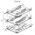
- two bases 38 are prepared. On one of the bases 20 is set the base sheet member 22 as in "1. Pre-arrangement of Base Sheet Member" described above, and then the base-side perforated plate 32a is set on the base sheet member 22. Subsequently, the elastomer liquid material P is poured into the perforations 34 of the base-side perforated plate 32a and then a portion of the liquid material P overflowing the perforations 34 is removed by means of a squeegee 48, to thereby form a base layer as shown in Fig. 14A (i).
- the air-permeable sheet 50 On the other base 38 is set the air-permeable sheet 50 as "2. Post-arrangement of Base Sheet member" described above and then the ground-side perforated plate 32b is arranged on the air-permeable sheet 50. Alternatiyely, when the perforated plate 32 is directly arranged on the base 38 without using the air-permeable sheet 50, a parting agent is applied to the base 38. Then, the ground-side perforated plate 32b is arranged on the base 38.
- the elastomer liquid material P is poured into the perforations 34 of the ground-side perforated plate 32b and then a portion of the liquid material P overflowing the perforations 34 is removed by means of a squeegee 48, to thereby form a ground layer as shown in Fig. 14A (ii).
- the ground layer is arranged on the base layer and a pressure is downwardly applied to a combination of the base layer and ground layer to cure the elastomer liquid material P to a degree sufficient to permit removal of the perforated plates.
- ground-side perforated plate 32b and base-side perforated plate 32a are removed in turn, to thereby fully cure the elastomer, resulting in such a rugged shaped sheet 20 as shown in Fig. 20 being prepared.
- the intermediate procedure described above permits the base layer and ground layer to be concurrently formed, to thereby contribute to an increase in productivity.
- Formation of an intermediate layer by means of the intermediate perforated plate 32c may be carried out by arranging the intermediate between the base-side perforated plate 32a and the ground-side perforated plate 32b and the elastomer liquid material P is poured into the perforations 34 of the intermediate perforated plate 32c, followed by a squeegee treatment, to thereby form the intermediate layer.
- the rugged shapes sheet 20 of the present invention is not limited to a sole of sports shoes.
- it may be effectively applied to stripes for design or reinforcement provided on an upper part of sports shoes; a grip for a bicycle, a tennis racket and a badminton racket; a saddle for a bicycle; a non-slip member for a snow board and a surfboard; a glove for athletics or sports such as baseball, soccer and bicycle racing; a grip for various kinds of tools; a grip for a camera and a video camera; and the like.
- the rugged shaped sheet of the present invention is so constructed that the rugged pattern is constituted by the plural pattern elements which are formed so as to be different in at least one of size, configuration and properties from each other, resulting in being constructed into a multi-layer structure.
- Such construction permits the rugged pattern to be provided thereon with a strip-or stripe-like color design when different colors are applied to the pattern elements, respectively, to thereby improve aesthetic properties of the rugged shaped sheet.
- the pattern elements of the rugged pattern are formed so as to be different in size or combination of size and configuration from each other, resulting in the rugged pattern being formed into a stepwise configuration, the rugged pattern may be formed into a more complicated configuration sufficient to further improve the aesthetic properties.
- the rugged pattern is successively formed from the base side or ground side, so that the properties, size and/or configuration of the pattern elements may be varied as required, resulting in the rugged shaped sheet of a complicated configuration required to provide non-slip properties being manufactured with ease and at a reduced cost.
Landscapes
- Engineering & Computer Science (AREA)
- Mechanical Engineering (AREA)
- Chemical & Material Sciences (AREA)
- Materials Engineering (AREA)
- Footwear And Its Accessory, Manufacturing Method And Apparatuses (AREA)
- Shaping Of Tube Ends By Bending Or Straightening (AREA)
- Casting Or Compression Moulding Of Plastics Or The Like (AREA)
Applications Claiming Priority (15)
| Application Number | Priority Date | Filing Date | Title |
|---|---|---|---|
| JP18592392 | 1992-06-19 | ||
| JP18592392 | 1992-06-19 | ||
| JP185923/92 | 1992-06-19 | ||
| JP307574/92 | 1992-10-21 | ||
| JP30757492A JP3218413B2 (ja) | 1992-06-19 | 1992-10-21 | エンボスシートの製造方法 |
| JP30757492 | 1992-10-21 | ||
| JP35190292 | 1992-12-09 | ||
| JP35190292A JP3239192B2 (ja) | 1992-12-09 | 1992-12-09 | 特殊形状エンボスの製造方法 |
| JP351902/92 | 1992-12-09 | ||
| JP6284393A JP3326506B2 (ja) | 1993-02-26 | 1993-02-26 | 凹凸成形シートの製造方法 |
| JP62843/93 | 1993-02-26 | ||
| JP6284393 | 1993-02-26 | ||
| JP16611093 | 1993-06-11 | ||
| JP16611093A JP3243699B2 (ja) | 1993-06-11 | 1993-06-11 | 凹凸成形シートの製造方法 |
| JP166110/93 | 1993-06-11 |
Publications (2)
| Publication Number | Publication Date |
|---|---|
| EP0577307A1 true EP0577307A1 (fr) | 1994-01-05 |
| EP0577307B1 EP0577307B1 (fr) | 1999-09-29 |
Family
ID=27523736
Family Applications (1)
| Application Number | Title | Priority Date | Filing Date |
|---|---|---|---|
| EP93304830A Expired - Lifetime EP0577307B1 (fr) | 1992-06-19 | 1993-06-21 | Feuille scabreuse et son procédé de réalisation |
Country Status (6)
| Country | Link |
|---|---|
| US (3) | US5389176A (fr) |
| EP (1) | EP0577307B1 (fr) |
| CN (1) | CN1066620C (fr) |
| DE (1) | DE69326581T2 (fr) |
| ES (1) | ES2139627T3 (fr) |
| SG (1) | SG72668A1 (fr) |
Cited By (3)
| Publication number | Priority date | Publication date | Assignee | Title |
|---|---|---|---|---|
| EP0850750A3 (fr) * | 1996-10-12 | 1998-09-30 | Robert Bosch Gmbh | Procédé pour la fabrication d'un produit à micropores, un cadre de moulage et un élément optique intégré |
| US7047668B2 (en) | 2003-07-24 | 2006-05-23 | Nike, Inc. | Article of footwear having an upper with a polymer layer |
| US20160101583A1 (en) * | 2014-10-09 | 2016-04-14 | Dah Lih Puh Co., Ltd. | Mold and method for making heterogeneous composite outer shoe sole |
Families Citing this family (40)
| Publication number | Priority date | Publication date | Assignee | Title |
|---|---|---|---|---|
| CN1066620C (zh) * | 1992-06-19 | 2001-06-06 | 铃木总业株式会社 | 凹凸成形层及其制造方法 |
| US5705970A (en) * | 1993-10-15 | 1998-01-06 | Kabushiki Kaisha Sankyo Seiki Seisakusho | Rare-earth containing iron-base resin bonded magnets |
| US6702559B1 (en) * | 1997-12-12 | 2004-03-09 | Jimmy W. Norman | Template for creating designs |
| JP2001213214A (ja) * | 2000-02-03 | 2001-08-07 | Eidai Kako Kk | 自動車用フロアーマット |
| US7018692B2 (en) * | 2000-07-06 | 2006-03-28 | Higher Dimension Medical, Inc. | Penetration resistant fabric with multiple layer guard plate assemblies and method of making the same |
| US6557272B2 (en) * | 2001-07-13 | 2003-05-06 | Luigi Alessio Pavone | Helium movement magnetic mechanism adjustable socket sole |
| JP2003039582A (ja) * | 2001-07-19 | 2003-02-13 | Three M Innovative Properties Co | 湿潤防滑性シート及び湿潤防滑構造体 |
| JP4326190B2 (ja) * | 2002-07-10 | 2009-09-02 | スリーエム イノベイティブ プロパティズ カンパニー | 可とう性成形型及びその製造方法 |
| US20060099871A1 (en) * | 2004-11-05 | 2006-05-11 | Kimberly-Clark Worldwide, Inc. | Reinforced elastic fiberous web |
| US20060213084A1 (en) * | 2005-03-23 | 2006-09-28 | Scales Cheryl D | Footwear insert and method of producing same |
| CN100471643C (zh) * | 2006-09-30 | 2009-03-25 | 立兆股份有限公司 | 使塑料在柔软布上成型的生产方法 |
| US20080081204A1 (en) * | 2006-10-02 | 2008-04-03 | Chien-Kang Ho | Elastic coated fabric and method for manufacturing the same |
| US20110056094A1 (en) * | 2008-03-14 | 2011-03-10 | Yanke Paul H | Magnetic boot attachment for a stirrup |
| US8371046B2 (en) * | 2008-03-14 | 2013-02-12 | Ontyte Llc | Stirrup |
| US20100031535A1 (en) * | 2008-08-05 | 2010-02-11 | Gregory Ross Leedy | Printed sole for a shoe and method of making |
| US8249887B2 (en) * | 2009-09-03 | 2012-08-21 | The Invention Science Fund I, Llc | Personalized plan development based on identification of one or more relevant reported aspects |
| US8772087B2 (en) * | 2009-10-22 | 2014-07-08 | Infineon Technologies Ag | Method and apparatus for semiconductor device fabrication using a reconstituted wafer |
| GB2540695C (en) | 2009-12-22 | 2017-10-25 | Fisher & Paykel Healthcare Ltd | Components for medical circuits |
| CN101884444A (zh) * | 2010-07-06 | 2010-11-17 | 张健 | 一种鞋底的制造方法及用该方法制造的鞋底 |
| DE102010055818A1 (de) * | 2010-12-23 | 2012-06-28 | Puma Aktiengesellschaft Rudolf Dassler Sport | Schuh, insbesondere Sportschuh, und Verfahren zum Herstellen eines Schuhs |
| KR20130127655A (ko) * | 2012-05-15 | 2013-11-25 | 엘지이노텍 주식회사 | 터치윈도우 및 그 제조방법 |
| US10945488B2 (en) | 2013-08-09 | 2021-03-16 | Reebok International Limited | Article of footwear with extruded components |
| MA40422A (fr) * | 2014-07-11 | 2017-05-17 | Geox Spa | Procédé de production de parties de chaussures imper-respirantes, parties de chaussures imper-respirantes produites au moyen dudit procédé et semelles imper-respirantes pourvues desdites parties de chaussures |
| US11019879B2 (en) * | 2015-11-18 | 2021-06-01 | Reebok International Limited | Extruded components for articles of footwear and methods of making the same |
| US10034519B2 (en) | 2016-06-16 | 2018-07-31 | Adidas Ag | UV curable lattice microstructure for footwear |
| CN108724599A (zh) * | 2017-04-18 | 2018-11-02 | 张仲甫 | 跑步机的按摩耐滑板成形方法及其成品 |
| EP4344571B1 (fr) | 2017-04-21 | 2025-07-02 | NIKE Innovate C.V. | Structure de semelle avec éléments proprioceptifs |
| US11136475B2 (en) | 2017-04-24 | 2021-10-05 | Nike, Inc. | Articles and components with UV radiation curable elastomeric materials and methods of making the same |
| WO2018200363A2 (fr) | 2017-04-24 | 2018-11-01 | Nike Innovate C.V. | Moule d'outillage transparent et procédé associé à du caoutchouc durcissable par rayonnement uv |
| CN114766781A (zh) | 2017-04-24 | 2022-07-22 | 耐克创新有限合伙公司 | 具有粘附至纺织品的uv辐射可固化材料的物品及其制造法 |
| WO2018200362A1 (fr) | 2017-04-24 | 2018-11-01 | Nike Innovate C.V. | Vêtement et équipement sportif comportant un matériau durcissable par rayonnement uv et son procédé de fabrication |
| WO2018200364A1 (fr) * | 2017-04-24 | 2018-11-01 | Nike Innovate C.V. | Articles et composants comprenant des matériaux élastomères durcissable par rayonnement uv et leurs procédés de fabrication |
| US11059249B2 (en) * | 2017-06-19 | 2021-07-13 | Under Armour, Inc. | Footwear and method of formation |
| US10485302B2 (en) | 2017-07-07 | 2019-11-26 | Reebok International Limited | Method of making an upper |
| US20190166952A1 (en) | 2017-12-05 | 2019-06-06 | Reebok International Limited | Article of footwear with dispensed saddle |
| US11472066B2 (en) * | 2018-06-18 | 2022-10-18 | Crayola Llc | Stackable/nesting stencil or mold system for modeling compound |
| US11278081B2 (en) | 2018-10-10 | 2022-03-22 | Reebok International Limited | Article of footwear with dispensed components |
| DE102018221393A1 (de) * | 2018-12-11 | 2020-06-18 | Rhenoflex Gmbh | Pulverauftragvorrichtung sowie Verfahren zur Herstellung von Versteifungselementen aus pulverförmigem Material |
| CN117999014A (zh) * | 2021-09-30 | 2024-05-07 | 耐克创新有限合伙公司 | 用于鞋类物品的鞋外底 |
| WO2023205297A1 (fr) * | 2022-04-20 | 2023-10-26 | Navail Emmanuel Benjamin Andre | Semelle magnétique et chaussure |
Citations (4)
| Publication number | Priority date | Publication date | Assignee | Title |
|---|---|---|---|---|
| BE357280A (fr) * | ||||
| FR2323521A1 (fr) * | 1975-09-11 | 1977-04-08 | Metzeler Kautschuk | Procede et dispositif pour fabriquer des corps stratifies, notamment des semelles de chaussures a plusieurs couches |
| US4364190A (en) * | 1980-08-14 | 1982-12-21 | Brs, Inc. | Outer sole for athletic shoe |
| JPH01310601A (ja) * | 1988-06-08 | 1989-12-14 | Asics Corp | 靴底の製造法 |
Family Cites Families (14)
| Publication number | Priority date | Publication date | Assignee | Title |
|---|---|---|---|---|
| US2264628A (en) * | 1939-08-03 | 1941-12-02 | Poster Products Inc | Advertising material |
| US4183978A (en) * | 1972-03-23 | 1980-01-15 | Kufner Textilwerke Kg | Raster-like coating of heat-sealable adhesives on substrates |
| DE2351405C3 (de) * | 1973-10-12 | 1979-05-17 | Kufner Textilwerke Kg, 8000 Muenchen | Verfahren zur Herstellung eines einseitig heiBsiegelfahigen Vlieses |
| JPS538569B2 (fr) * | 1974-12-28 | 1978-03-30 | ||
| JPS604796B2 (ja) * | 1976-12-29 | 1985-02-06 | 大日本印刷株式会社 | 防染用転写シート |
| US4324815A (en) * | 1978-01-24 | 1982-04-13 | Mitani Electronics Industry Corp. | Screen-printing mask and method |
| DE2813958A1 (de) * | 1978-03-31 | 1979-10-04 | Funck Herbert | Schuhsohle |
| DE3338557A1 (de) * | 1983-10-24 | 1985-05-02 | Puma-Sportschuhfabriken Rudolf Dassler Kg, 8522 Herzogenaurach | Sportschuh mit einer stossdaempfenden laufsohle und verfahren zur herstellung eines derartigen sportschuhes |
| US4986496A (en) * | 1985-05-31 | 1991-01-22 | Minnesota Mining And Manufacturing | Drag reduction article |
| US4676010A (en) * | 1985-06-10 | 1987-06-30 | Quabaug Corporation | Vulcanized composite sole for footwear |
| US4897936A (en) * | 1988-02-16 | 1990-02-06 | Kaepa, Inc. | Shoe sole construction |
| US4991990A (en) * | 1990-01-05 | 1991-02-12 | Minnesota Mining And Manufacturing Company | Photograph album attachment assembly |
| JP2968555B2 (ja) * | 1990-05-10 | 1999-10-25 | 理想科学工業株式会社 | 成形型の作製方法 |
| CN1066620C (zh) * | 1992-06-19 | 2001-06-06 | 铃木总业株式会社 | 凹凸成形层及其制造方法 |
-
1993
- 1993-06-19 CN CN93109450A patent/CN1066620C/zh not_active Expired - Lifetime
- 1993-06-21 EP EP93304830A patent/EP0577307B1/fr not_active Expired - Lifetime
- 1993-06-21 DE DE69326581T patent/DE69326581T2/de not_active Expired - Lifetime
- 1993-06-21 SG SG1996008281A patent/SG72668A1/en unknown
- 1993-06-21 US US08/079,376 patent/US5389176A/en not_active Expired - Lifetime
- 1993-06-21 ES ES93304830T patent/ES2139627T3/es not_active Expired - Lifetime
-
1996
- 1996-01-04 US US08/582,897 patent/US5709763A/en not_active Expired - Fee Related
-
1997
- 1997-10-20 US US08/954,095 patent/US5853854A/en not_active Expired - Lifetime
Patent Citations (4)
| Publication number | Priority date | Publication date | Assignee | Title |
|---|---|---|---|---|
| BE357280A (fr) * | ||||
| FR2323521A1 (fr) * | 1975-09-11 | 1977-04-08 | Metzeler Kautschuk | Procede et dispositif pour fabriquer des corps stratifies, notamment des semelles de chaussures a plusieurs couches |
| US4364190A (en) * | 1980-08-14 | 1982-12-21 | Brs, Inc. | Outer sole for athletic shoe |
| JPH01310601A (ja) * | 1988-06-08 | 1989-12-14 | Asics Corp | 靴底の製造法 |
Non-Patent Citations (1)
| Title |
|---|
| PATENT ABSTRACTS OF JAPAN vol. 014, no. 106 (C - 694) 27 February 1990 (1990-02-27) * |
Cited By (4)
| Publication number | Priority date | Publication date | Assignee | Title |
|---|---|---|---|---|
| EP0850750A3 (fr) * | 1996-10-12 | 1998-09-30 | Robert Bosch Gmbh | Procédé pour la fabrication d'un produit à micropores, un cadre de moulage et un élément optique intégré |
| US7047668B2 (en) | 2003-07-24 | 2006-05-23 | Nike, Inc. | Article of footwear having an upper with a polymer layer |
| US20160101583A1 (en) * | 2014-10-09 | 2016-04-14 | Dah Lih Puh Co., Ltd. | Mold and method for making heterogeneous composite outer shoe sole |
| US9648923B2 (en) * | 2014-10-09 | 2017-05-16 | Dah Lih Puh Co., Ltd. | Mold and method for making heterogeneous composite outer shoe sole |
Also Published As
| Publication number | Publication date |
|---|---|
| US5709763A (en) | 1998-01-20 |
| EP0577307B1 (fr) | 1999-09-29 |
| DE69326581T2 (de) | 2000-06-08 |
| CN1085756A (zh) | 1994-04-27 |
| US5853854A (en) | 1998-12-29 |
| ES2139627T3 (es) | 2000-02-16 |
| CN1066620C (zh) | 2001-06-06 |
| SG72668A1 (en) | 2000-05-23 |
| US5389176A (en) | 1995-02-14 |
| DE69326581D1 (de) | 1999-11-04 |
Similar Documents
| Publication | Publication Date | Title |
|---|---|---|
| EP0577307B1 (fr) | Feuille scabreuse et son procédé de réalisation | |
| US6007437A (en) | Structural foam basketball backboard with inmold graphics | |
| US6605333B2 (en) | Floor mat having bottom surface of concave sections and nubs | |
| US5931752A (en) | Inflatable game ball with laid-in channel or logo | |
| US5586354A (en) | Method for forming patterns on shoe sole | |
| EP0376263A2 (fr) | Procédé et moule de fabrication d'un objet moulé stratifié | |
| JPH04314461A (ja) | 水泳用ひれおよびその製造方法 | |
| JP3401586B2 (ja) | 凹凸成形シート並びにその製造方法 | |
| EP0376264A2 (fr) | Procédé et moule de fabrication d'un objet moulé stratifié | |
| JP3243699B2 (ja) | 凹凸成形シートの製造方法 | |
| JPH01265979A (ja) | 競技用ボールの表面パネル及びその製造方法 | |
| US20020074692A1 (en) | Bathmat and the method for manufacturing the same | |
| JPH06826A (ja) | エンボスシートの製造方法 | |
| JP2010005384A (ja) | しるしを有するボーリングボール及びその作成方法 | |
| JP3016166B2 (ja) | エンボスシート並びにその製造方法並びにこれを使用した靴底 | |
| US7115225B2 (en) | Pseudo insert molding for trim parts using polyurethane spray process | |
| KR100236855B1 (ko) | 요철 성형 판 및 그 제조 방법 | |
| US20040262819A1 (en) | Method for forming patterns on shoe sole | |
| JP3491241B2 (ja) | 機能性シートの製造方法 | |
| JPH0870906A (ja) | 凹凸成形シート並びにその製造方法 | |
| JPH06154008A (ja) | 靴底並びにエンボスシートの製造方法 | |
| JP3326506B2 (ja) | 凹凸成形シートの製造方法 | |
| JPH0852760A (ja) | 印刷化粧積層材 | |
| KR960001654B1 (ko) | 입체감을 갖는 고광택 장식무늬판 및 그 제조방법 | |
| JPH0825387A (ja) | 樹脂成形体の製造方法 |
Legal Events
| Date | Code | Title | Description |
|---|---|---|---|
| PUAI | Public reference made under article 153(3) epc to a published international application that has entered the european phase |
Free format text: ORIGINAL CODE: 0009012 |
|
| AK | Designated contracting states |
Kind code of ref document: A1 Designated state(s): CH DE ES FR GB IT LI NL SE |
|
| 17P | Request for examination filed |
Effective date: 19940509 |
|
| 17Q | First examination report despatched |
Effective date: 19950830 |
|
| GRAG | Despatch of communication of intention to grant |
Free format text: ORIGINAL CODE: EPIDOS AGRA |
|
| GRAG | Despatch of communication of intention to grant |
Free format text: ORIGINAL CODE: EPIDOS AGRA |
|
| GRAH | Despatch of communication of intention to grant a patent |
Free format text: ORIGINAL CODE: EPIDOS IGRA |
|
| GRAH | Despatch of communication of intention to grant a patent |
Free format text: ORIGINAL CODE: EPIDOS IGRA |
|
| GRAA | (expected) grant |
Free format text: ORIGINAL CODE: 0009210 |
|
| AK | Designated contracting states |
Kind code of ref document: B1 Designated state(s): CH DE ES FR GB IT LI NL SE |
|
| PG25 | Lapsed in a contracting state [announced via postgrant information from national office to epo] |
Ref country code: SE Free format text: THE PATENT HAS BEEN ANNULLED BY A DECISION OF A NATIONAL AUTHORITY Effective date: 19990929 Ref country code: LI Free format text: LAPSE BECAUSE OF FAILURE TO SUBMIT A TRANSLATION OF THE DESCRIPTION OR TO PAY THE FEE WITHIN THE PRESCRIBED TIME-LIMIT Effective date: 19990929 Ref country code: CH Free format text: LAPSE BECAUSE OF FAILURE TO SUBMIT A TRANSLATION OF THE DESCRIPTION OR TO PAY THE FEE WITHIN THE PRESCRIBED TIME-LIMIT Effective date: 19990929 |
|
| ITF | It: translation for a ep patent filed | ||
| REG | Reference to a national code |
Ref country code: CH Ref legal event code: EP |
|
| REF | Corresponds to: |
Ref document number: 69326581 Country of ref document: DE Date of ref document: 19991104 |
|
| ET | Fr: translation filed | ||
| REG | Reference to a national code |
Ref country code: ES Ref legal event code: FG2A Ref document number: 2139627 Country of ref document: ES Kind code of ref document: T3 |
|
| REG | Reference to a national code |
Ref country code: CH Ref legal event code: PL |
|
| PLBE | No opposition filed within time limit |
Free format text: ORIGINAL CODE: 0009261 |
|
| STAA | Information on the status of an ep patent application or granted ep patent |
Free format text: STATUS: NO OPPOSITION FILED WITHIN TIME LIMIT |
|
| 26N | No opposition filed | ||
| REG | Reference to a national code |
Ref country code: GB Ref legal event code: IF02 |
|
| PGFP | Annual fee paid to national office [announced via postgrant information from national office to epo] |
Ref country code: NL Payment date: 20120629 Year of fee payment: 20 |
|
| PGFP | Annual fee paid to national office [announced via postgrant information from national office to epo] |
Ref country code: GB Payment date: 20120629 Year of fee payment: 20 |
|
| PGFP | Annual fee paid to national office [announced via postgrant information from national office to epo] |
Ref country code: IT Payment date: 20120621 Year of fee payment: 20 |
|
| PGFP | Annual fee paid to national office [announced via postgrant information from national office to epo] |
Ref country code: DE Payment date: 20120830 Year of fee payment: 20 Ref country code: ES Payment date: 20120717 Year of fee payment: 20 Ref country code: FR Payment date: 20120720 Year of fee payment: 20 |
|
| REG | Reference to a national code |
Ref country code: DE Ref legal event code: R071 Ref document number: 69326581 Country of ref document: DE |
|
| REG | Reference to a national code |
Ref country code: NL Ref legal event code: V4 Effective date: 20130621 |
|
| REG | Reference to a national code |
Ref country code: GB Ref legal event code: PE20 Expiry date: 20130620 |
|
| PG25 | Lapsed in a contracting state [announced via postgrant information from national office to epo] |
Ref country code: DE Free format text: LAPSE BECAUSE OF EXPIRATION OF PROTECTION Effective date: 20130622 Ref country code: GB Free format text: LAPSE BECAUSE OF EXPIRATION OF PROTECTION Effective date: 20130620 |
|
| REG | Reference to a national code |
Ref country code: ES Ref legal event code: FD2A Effective date: 20140828 |
|
| PG25 | Lapsed in a contracting state [announced via postgrant information from national office to epo] |
Ref country code: ES Free format text: LAPSE BECAUSE OF EXPIRATION OF PROTECTION Effective date: 20130622 |