EP0577689B1 - Leitersteigen und daraus hergestellte leiter - Google Patents
Leitersteigen und daraus hergestellte leiter Download PDFInfo
- Publication number
- EP0577689B1 EP0577689B1 EP92907682A EP92907682A EP0577689B1 EP 0577689 B1 EP0577689 B1 EP 0577689B1 EP 92907682 A EP92907682 A EP 92907682A EP 92907682 A EP92907682 A EP 92907682A EP 0577689 B1 EP0577689 B1 EP 0577689B1
- Authority
- EP
- European Patent Office
- Prior art keywords
- stile
- ladder
- tension
- compression
- spacing portion
- Prior art date
- Legal status (The legal status is an assumption and is not a legal conclusion. Google has not performed a legal analysis and makes no representation as to the accuracy of the status listed.)
- Expired - Lifetime
Links
Images


Classifications
-
- E—FIXED CONSTRUCTIONS
- E06—DOORS, WINDOWS, SHUTTERS, OR ROLLER BLINDS IN GENERAL; LADDERS
- E06C—LADDERS
- E06C7/00—Component parts, supporting parts, or accessories
- E06C7/08—Special construction of longitudinal members, or rungs or other treads
Definitions
- This invention relates to ladder stiles and ladders formed therefrom.
- it relates to strong, lightweight, non-conducting ladders and ladder stiles.
- This invention relates to ladder stiles and ladders produced therefrom.
- the thickness of the ladder stiles cannot be further reduced because it is the depth of the housing of the rungs into the stiles which gives the ladder its diagonal bracing, its resistance to twist and its overall structural integrity.
- thinner section timber ladders are subject to the drawbacks of being weaker overall structures which only partially solve the excessive weight problem.
- Traditional timber ladders also commonly include reinforcing material in the form of a rod running the length of the stile. While this reinforcing material has a moderate effect in increasing the strength and stiffness of the ladder stile, its main purpose is to act as a "safety net" in the unlikely event of a ladder stile breaking into two pieces when in use. Should this happen, the reinforcing material serves to hold the severed pieces together and to prevent the complete collapse of the ladder until such time as the user has been able to descend.
- a wire reinforcing rod is stapled into a groove on the outside edge of the ladder stile. The disadvantage with this system is that the wire can simply "unzip” by springing all the staples in quick succession.
- an object of the present invention to provide a ladder stile which will go some way towards overcoming the abovementioned disadvantages by providing a lightweight non-conducting ladder stile and ladders formed therefrom, or which at least provides the public with a useful choice.
- CH-A-478330 discloses a stile for a ladder comprising:
- the present invention is characterised in that the said compression, tension and spacing portions are respectively separate and discrete portions and the spacing portion comprises two sections with a resilient membrane laminated between the two sections.
- the ladder stile of the present invention may also include reinforcing material.
- the present invention provides a ladder comprising a pair of parallel stiles of the invention interconnected by rungs.
- the present invention relates to a ladder stile.
- a ladder stile is suitable for use in the production of lightweight non-conducting ladders.
- the stile is particularly suitable for use in the production of one person portable ladders, and also in areas where electricity may present a danger.
- the ladder stile of the present invention comprises an elongate body. It is preferred that the elongate body be substantially rectangular in section as shown in the accompanying drawings. However, other appropriate shapes for the body, for example square, circular or hexagonal may be employed. It is also preferred that the ladder stile be deeper in cross section than those stiles conventionally employed in the art so as to provide a stronger, stiffer overall structure. It will be appreciated that the precise dimensions of the stile may vary substantially in length, depth and width.
- the ladder stile is designated generally as 20 in the accompanying drawings.
- the stile 20 may be produced from soft timbers and the completed stile 20 hardened.
- suitable materials for use in producing the ladder stiles 20 of the invention are hard and soft timbers, hardened soft timbers, and plywoods.
- Timbers particular preferred for use in the ladder stiles 20 are high quality durable timbers including ash, hickory and native New Zealand beech, and light weight timbers including pine and fir.
- the ladder stile 20 may be comprised of a single timber or a combination of timbers, in practice a combination of timbers is used. The presently preferred combination of timbers is beech and pine.
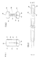
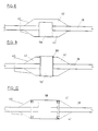
- the ladder stile 20 comprises three main portions, a compression portion 22, a tension portion 24 and a spacing portion 26, as illustrated in the accompanying drawings.
- compression portion it will be understood that this is the portion of the stile disposed closest to the operator when in use.
- the "compression portion” will comprise a portion of the stile equivalent to the compression portions illustrated in the other accompanying drawings.
- the compression portion 22 bears a compression edge 28 and has a substantially uniform cross-section over the length of the stile.
- the compression portion 22 may be of any shape convenient for such a compression portion 22. Examples of suitable shapes for the compression portion 22 as viewed in plan include substantially rectangular, pentagonal, "T", "U” or staple shapes as illustrated in Figures 1, 2, 5 to 7, 11 to 14 and 15. In the presently preferred embodiment the shape of the compression portion 22 is substantially rectangular. It will be appreciated that the dimensions of the compression portion may vary. Generally, the width of the compression portion is between substantially 25 to 40 mm with a width of substantially 33 mm being favoured. The depth of the compression portion varies widely within the range of from substantially 10 to 30 mm. A depth of between substantially 18 to 25 mm is preferred.
- the compression portion 22 of the ladder stile 20 is a portion under stress.
- the materials selected for the compression portion 22 will appropriately reflect this stress factor. Accordingly, it is preferred that the compression portion 22 be comprised of hard durable timbers or hardened soft timbers. Examples of suitable hard timbers include hickory, ash and native New Zealand beech. Native beech is the timber presently preferred.
- tension portion refers to that portion of the ladder stile 20 disposed farthest away from the operator when in use.
- the tension portion 24 bears a tension edge 30 and has a substantially uniform cross-section over the length of the stile.
- the tension portion 24 as with the compression portion 22, may be of any shape convenient for such a tension portion 24. While the tension and compression portions 24 and 22 respectively may have different shapes and dimensions, desirably they will be substantially the same shape and size. As with the compression portion 22 the tension portion 24 of the ladder stile 20 is stressed. Accordingly, any materials or combination of materials suitable for use in the compression portion 22 may also be employed in the tension portion 24.
- edges 28 and 30 are substantially parallel to one another.
- the tension and compression edges 30 and 28 define the width of the stile 20.
- the third portion of the ladder stile 20 is spacing portion 26.
- the spacing portion 26 of the ladder stile 20 structurally interconnects the tension and compression portions 24 and 22. Interconnection may be achieved by any means known in the art including tongue and groove connection, gluing or laminating. Preferably, portions 22, 24 and 26 are glued or laminated together.
- the spacing portion 26 is a relatively unstressed portion of the ladder stile 20. Accordingly, light weight materials are generally preferred. Suitable general classes of lightweight materials include pine and fir timber, hardened soft timbers, and plywoods. A particularly preferred lightweight material for use in the spacing portion 26 is pine.
- the spacing portion 26 has a cross-section which varies over the length of the stile 20. The variation occurs in a substantially regular repeating pattern.
- the dimensions of the cross section will vary within a broad range.
- the depth of the spacing portion 26 is between 35 to 55 mm and the width is between substantially 5 to 45 mm.
- the depth is between substantially 40 to 50 mm and the width is between substantially 7 to 40 mm.
- the shape employed for the spacing portion 26, where it is the full width of the stile 20, may be any shape known in the art. Examples of appropriate shapes for the spacing portion 26 include rectangles, squares, hexagons, and I shapes. Of these, the spacing portion 26 will desirably be substantially rectangular in shape, as illustrated in Figures 1, 2, 5 to 7, 11 to 14 and 15.
- the spacing portion 26 is comprised of two sections 32 which may be the same or different in both shape and the materials from which they are formed. However, as shown in Figures 1, 2, 5, 11 and 12, they will preferably be of the same shape, and formed of the same material.
- the sections 32 are joined together along a single centre line 34.
- the sections 32 may be joined together by any suitable means conventionally employed in the art including gluing or laminating.
- the sections 32 are desirably selected so as to change the direction of the timber fibres at the centre line 34. This change in direction of the fibres aids in reducing the tendency of the timber to split under stress.
- the spacing portion 26 is further provided with a resilient membrane 36 inter-connecting the sections 32.
- the resilient membrane 36 acts as an anti-split membrane.
- the resilient membrane 36 may extend lengthwise of the spacing portion 26 only, or may optionally be keyed to the tension and/or compression portions 24 and 22.
- the resilient membrane 36 may be keyed to the tension and compression portions 24 and 22 by any of the conventional means referred to above or otherwise known in the art.
- the resilient membrane 36 may be made of any material known in the art which will aid in the prevention of splitting. Examples of suitable materials include but are not limited to plywood, timber veneer, fibreglass cloth and other composite materials. In the presently preferred embodiment plywood is used.
- the spacing portion 26 when it is substantially the full width of the stile 20, may be comprised of more than two pieces of material 32.
- This -bWimerit is illustrated in Figures 6 to 10 and 13 to 16 of the accompanying drawings.
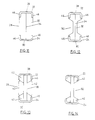
- the spacing portion 26 may be comprised of a spacer 38, and packing means 40 disposed either side of said spacer 38.
- the spacer 38 is an elongate member, desirably rectangular in shape, although other appropriate shapes may be employed.
- the spacer 38 is connected to both the tension and compression portions 24 and 22 by such suitable means as are known in the art including gluing and laminating.
- the spacer 38 may be connected to the tension and compression portions 24 and 22 at any given point. Desirably however, the spacer is connected to the tension and compression portions 24 and 22 at a point substantially mid-width of each of the portions 24 and 22.
- the spacer 38 may be made of any of the materials or combinations of materials set out above in relation to the stile 20.
- the spacer 38 is made of a lightweight material such as plywood or marine plywood.
- the packing means 40 of the spacing portion 26 will be substantially complementary in shape to these spaces defined between the tension and compression portions 24 and 22 and the spacer 38. Generally, the packing means 40 will not exceed the width of the stile as delimited by the tension and compression edges 30 and 28 respectively.
- the packing means 40 may consist of a single packing unit or multiple packing units 42 disposed either side of the spacer 38. Suitable packing materials include all of those materials set out above for the stile 20 either alone or in combination. Preferably, a lightweight material such as pine or fir will be used.
- the packing means 40 may be joined to the tension and compression portions 24 and 22 and the spacer 38 by conventional means including gluing or laminating. In an alternate form the packing means may be connected to the spacer 38 by bolting, gluing or riveting as illustrated in Figure 10.
- the spacing portion 26 may be comprised of two or more elongate spacers 38 inter-connecting the tension and compression portions 24.
- two spacers 38 will be used.
- the two spacers 38 may be connected to the tension and compression portions 24 and 22 at any given point.
- the spacers 38 are connected in such a way that the outer edges 44 of the spacers 38 are substantially parallel to the outer edges 46 of the tension and compression portions 24 and 22.
- a separate central body 48 is defined between the spacers 38 and the tension and compression portions 24 and 22.
- the central body 48 comprises packing means 40 as discussed above.
- the body 48 may consist of one or more packing units 42 and may be made of one or more materials.
- the materials employed for the spacers 38 and the central body 48 may be any of the materials suitable for use in the spacers 38 and packing means 40 set out above. similarly, the spacers 38 and central body 48 will be connected to the tension and compression portions 24 and 22, and to each other, by any conventional means already discussed.
- the spacing portion 26 also incorporates sections wherein at least a part of the spacing portion 26 is less than the full width of the stile 20.
- the spacing portion 26 is comprised of one or two sections 32 the reduction of at least part of the spacing portion 26 to a width narrower than the full width of the stile 20 may be achieved by removing part or all of sections 32, and from one or more sides of the spacing portion.
- a part of the sections 32 will be removed from either side of the spacing sections 32 to define recesses 50 as indicated in Figures 2, 4, 11, 12 and 14 of the accompanying drawings. Removal of material may be achieved by any conventional means such as machining.
- the shape of the recess 50 defined by removal of the material will be substantially trapezoid in plan. However, recesses 50 of alternate shapes may also be used.
- the spacing portion 26 is comprised of a single spacer 38 and packing means 40 the reduction in width of at least a part of the spacing portion 26 to less than the full width of the stile 20 is achieved by the omission or whole or part removal of the packing means 40.
- Packing means 40 may be omitted or removed from either one or both sides of the spacer 38 as illustrated in Figures 7 to 10, 13 and 14. Desirably, the packing means will be removed from both sides of the spacer to define recesses 50.
- the omission or removal of the packing means may be achieved by any convenient method known in the art.
- the spacing portion 26 is comprised of two or more spacers as illustrated in Figures 15 and 16 the reduction in width of at least a part of the spacing portion 26 is achieved by the omission or removal in whole or part of the central body 48 to define recess 52.
- the tension and compression portions 24 and 22 are narrow then less packing material will be removed.
- recess 52 is treated or filled with a moisture excluding agent to prevent the ingress of water into the stile 20.
- a moisture excluding agent Any known moisture excluding agents may be used.
- a preferred material is a moisture excluding foam which fills the recess 52.
- the ladder stile 20 is additionally provided with reinforcing material as illustrated in Figures 1, 2, 5 and 7.
- the reinforcing material may be provided in any suitable form known in the art such as a strip or rod running the length of the ladder stile.
- a reinforcing rod 54 is preferred. When a reinforcing rod 54 is present, it may used in either the tension and compression portions 24 and 22. In the case of single ladders it is preferred that reinforcing rods be present in both the tension and compression portions 24 and 22, principally to take account of the fact that inattentive operators tend to use the ladder either way up.
- a single reinforcing rod is used in the tension portion 24 of the ladder stile 20.
- the reinforcing rod 54 may be located in the tension and/or compression edges 30 and/or 38 as with traditional timber ladders. Desirably however, the reinforcing rod is placed in a position internal of the tension and compression edges 30 and 28 where it is protected from wear and damage and to eliminate the problem of the reinforcing rod becoming unzipped from the stile in the case of breakage, as happens with traditional timber ladders.
- Suitable reinforcing rod materials include fibreglass, strong composites, and wire. Where wire is used, it should preferably be firmly anchored to one end of the ladder stile 20 by any conventional means, and to the other end of the ladder stile 20 by means of a threaded rod with a nut attached (not shown). Such means are well known in the art. It will be appreciated that this arrangement can be used to tension the wire, and therefore stiffen the ladder stile 20, by tightening the nut on the threaded rod.
- the reinforcing material of preference is fibreglass rod.
- the ladder stile of the invention may also incorporate rung attachmmt means.
- rung receiving recesses 58 are provided in the stile 20. Desirably, rung recesses 58 will be formed only in the spacing portion 26 of the stiles 20 and only at those sections of the spacing portion 26 where substantially the entire spacing portion 26 is the full width of the stile 20.
- the recesses 58 may be of any shape suitable for receiving and holding a ladder rung and may be formed through any known methods such as machining.
- the rung recesses 58 may pass through the entire width of the spacing portion as illustrated in Figures 9 and 10. However, it is preferred that the recesses 58 pass only partway through the spacing portion 26 and from one side only as shown in Figures 4, 8, 9 and 16.
- a protective material 60 may be inserted into the recess 58 as shown in Figure 9.
- metal protective material may be laid over the entire width of the spacing portion 26 and attached by such means as are known in the art including gluing, riveting and screwing.
- Preferred protective materials include metal tubing and metal plate.
- the wood of the rung recess may be hardened using known techniques to reduce splitting of the timber.
- the present invention relates to a lightweight non-conducting ladder comprising two stiles 20 of the invention interconnected by rungs (not shown). While other variations are possible it is preferred that the stiles 20 be substantially parallel to one another.
- the rungs may be of any shape conventionally employed in the art for such ladder rungs. Examples of suitable shapes as viewed in longitudinal section include circles, squares and rectangles but are not limited thereto. Presently preferred are rungs which are substantially round. Particularly preferred are round rungs with grip-ridges over the entire surface or most preferably on the upper surface only.
- Materials suitable for use in the ladder rungs include any conventional material known or used for ladder rungs. The presently preferred material is aluminium.
- interconnection of the stiles 20 and the rungs may be achieved by any means known in the art.
- the rungs of the ladder may be held in the recesses 58 by any conventional means including tongue and groove, gluing, screwing, and riveting. In the presently preferred embodiment the rungs are held in place by screws.
- the ladder stiles of the invention are formed by appropriately assembling a spacing portion, hardwood tension and compression portions and a fibreglass reinforcing rod.
- Spacing portion sections of substantially 40-50 mm in depth and substantially 20 mm in width are produced by rip sawing to the requisite dimensions.
- the resulting acceptable sections are machined to produce "fingered" ends so that successive lengths of section may be joined together by way of finger joints.
- the jointing may be carried out on a finger jointing machine, or failing this, by mounting the timber on a sliding carriage and passing the timber in front of a spinning cutter head mounted on a spindle.
- a commercially available resorcinol glue (a mix of glue resin and hardener) is applied to the fingers and complementary fingers pressed together to form the finger joint. The jointing procedure is repeated until sections of a preselected length are produced.
- the hardwood tension and compression portions of the stile are formed from beech wood dried to a moisture content of between substantially 10 to 12%. This timber is rip sawed to a preselected cross section size of between substantially 18 to 25 mm in depth and substantially 36 mm in width. As with the softwood spacing portion sections the hardwood timber is then "defected" to produce timber lengths with a grain slope maximum of 1 in 12.
- Selected ends of the timber are then cut at an angle to produce a length of timber having a one sided point with a slope of approximately 1 in 12.
- Scarf joints are produced by gluing complementary sloping lengths of timber together. A resorcinol glue is again used. The scarf joint is clamped or pressed to allow the glue to cure. The curing process may be accelerated through the application of heat. The scarf jointing procedure is repeated until a piece of timber of a preselected length is produced.
- the resultant length of hardwood timber is machined or dressed to the preselected cross-section dimensions, through a multi-head moulding machine. As the timber passes through the moulding machine a reinforcing rod groove or grooves may also be machined into the length of timber. The finished hardwood edge is then stored.
- Fibreglass reinforcing rod complying with any National safety standards specifications is obtained or cut to preselected lengths.
- the surface of the rod is abraded to remove wax and to provide a good key for the epoxy glue used to attach the fibreglass rod to the timber surface.
- the rod is also stored pending assembly of the ladder stile.
- a multiple lamination step is performed. Resorcinol and epoxy glues for lamination are prepared and applied to the timber, a plywood antisplit membrane and the reinforcing rod as appropriate.
- the stile is assembled with the plywood membrane disposed between two spacing portion sections, with the reinforcing rod in the purpose cut groove(s), and with the hardwood tension and compression portions disposed at either end of the assembled spacing portion.
- the stile as assembled is clamped together in a purpose built press. Sideways and edgeways pressure is applied using compressed air to clamp all joints tightly together.
- Radio frequency induction heating is applied across the glue joints from the front face of the stile to the opposite face to heat the glue and accelerate the setting process.
- An average setting time is between 2 to 4 minutes when heated. The completed stile is then left to cool.
- the completed stile is passed through a multi-head moulding machine in which the cross-section is sized, all faces and edges are smoothed, and corners rounded.
- the stiles are then trimmed to the exact pre-selected length.
- finishing steps are effected. These steps may be carried out separately but sequentially or as part of an automated sequence.
- the finishing steps comprise:
- the ladders of the present invention are produced by interconnecting two ladder stiles of the invention with rungs.
- the rungs are formed of extruded aluminium tubing incorporating grip-ridges.
- the tubing is cut to a preselected length, and the ends "spigoted" by machining off the grip ridges. Holes for receiving the rung securing screws are drilled through the rungs at the spigoted ends.
- the ladder to be produced is an extension ladder
- metal fittings such as brackets and arms, pulleys and rope are attached as for conventional extension ladders.
- This embodiment requires the use of a hard, durable timber, such as beech or ash, in the stressed tension and compression portions of the ladder stile, laminated to a lighter timber such as pine or fir in the less stressed spacing portion.
- the spacing portion is comprised of two sections connected along a central join. To provide a section wherein the width of the spacing portion is at least in part less than the entire width of the stile the material of the spacing portion has been machined away on both sides of the ladder stile to define two recesses as shown in Figure 2.
- This embodiment also incorporates the feature of reinforcing the tension portion with fibreglass, or a similar very strong composite rod running the full length of the ladder stile. Reinforcing material is used in the tension portion of the ladder stile as illustrated in Figures 1 and 2.
- This embodiment encompasses all the features of Example One but has the additional feature that the splitting resistance of the spacing portion of the stile has been considerably enhanced by the use of a plywood antisplit membrane laminated between the two sections of the spacing portion as illustrated in Figure 5.
- the spacing portion is comprised of a single spacer and one or more packing means.
- the spacer is a length of plywood glued into the hardwood timber tension and compression portions.
- the packing means is glued in place or alternatively, as shown in Figure 1 the packing means is bolted to the spacer.
- This embodiment also incorporates all of the features of the previous two examples relating to the options for reinforcing the stile.
- This embodiment shown in Figures 13 and 14 is a variation incorporating the plywood spacer of Example Three.
- This embodiment incorporates plywood as a non-splittable, lightweight spacer in the spacing portion of the stile.
- the tension and compression portions are formed of timber.
- the spacer is conveniently glued to the stressed edges.
- the spacing portion is also comprised of suitable packing means.
- the packing means comprises a number of different units made of different materials.
- the central packing unit is made from lightweight pine timber while the end units are of harder beech timber.
- the harder wood in the end packing units provides for better connection between the compression portions and the spacer of the spacing portion. While all of the parts of the stile are conveniently laminated together, the packing means may also be connected to the spacer by the method exemplified in Figure 10.
- Example Three This embodiment is similar to Example Three. Beech timber is used to form the tension and compression portions. As shown in Figures 15 and 16 the spacing portion comprises two spacers and a central body or packing means.
- the cross-section of the spacing portion varies from the embodiment shown in Figures 15 to an embodiment wherein the packing material is omitted from the spacing portion as illustrated in Figure 16.
- the recess formed from the omission of the packing material is desirably filled with a moisture excluding foam.
- reinforcing may be used if desired.
- a lightweight, nonconducting ladder stile and ladder incorporating the stiles of the invention incorporating the stiles of the invention.
- the advantage of the ladders and stiles is that they are designed to be non-conducting through judicious selection of materials, making them safe for use in areas where electricity may present a danger.
- a further advantage of the stiles and ladders of the invention is that they have a reduced weight achieved by eliminating or omitting material from the relatively unstressed spacing portion of the stile at selected sections and essentially between the points of attachment for the ladder rungs.
- the overall weight is significantly reduced without compromising the structural integrity of the stile or any ladder in which it is to be used.
- the employment of this invention enables stiles of greater depth to be built which are lighter in weight than traditional timber ladders. Moreover, these stiles of greater depth are stiffer and stronger without the previous weight penalty.
- ladder stile portions which are at once stronger, more hard wearing, and less prone to production of splinters at sites of damage than conventional timber ladder stiles while still retaining the advantage of being substantially lighter in weight.
- New Zealand timbers such as high quality, strong, native beech, of which there is an abundant supply, in combination with light weight pine timber which is also in plentiful supply avoids the difficulty of diminishing supply of traditional materials.
- use of a dark coloured beech wood, in combination with lighter coloured pine timber provides a ladder stile which is a very aesthetically pleasing arrangement.
- reinforcing material provides for an increase in the strength and stiffness of the ladder stile as well as acting as a safety net.
- the ladders of the present invention which incorporate the reinforcing material at a point internal of the stile provide considerable advantages over conventional ladders. When the reinforcing material is in an internal position, it is protected from wear and damage and can not "unzip" as in the case of conventional ladders. Further, when wire reinforcing is used in an internal position the ladder ceases to be a danger to users in the electricity industry where exposed wires can conduct electricity to the users hand.
- Both the ladder stiles and ladders of the present invention may also incorporate such optional features as protective guards over the ends of the ladder stiles, and means for attaching fittings to the ladder stile including brackets and arms required for extension ladders. Further, the stiles and ladders may be protectively coated, treated, painted or otherwise embellished, if desired.
Landscapes
- Engineering & Computer Science (AREA)
- Mechanical Engineering (AREA)
- Ladders (AREA)
- Steps, Ramps, And Handrails (AREA)
- Programmable Controllers (AREA)
Claims (5)
- Holm für eine Leiter, umfassend: einen Druckabschnitt, der eine Druckkante trägt und einen im wesentlichen gleichförmigen Querschnitt über die Länge des Holms aufweist, und der eine Längsmittelachse über die gesamte Länge des Holms aufweist; einen Zugabschnitt, der eine Zugkante trägt und der einen im wesentlichen gleichförmigen Querschnitt über die Länge des Holms aufweist, und der eine Längsmittelachse über die gesamte Länge des Holms aufweist; wobei der Druck- und der Zugabschnitt über die Länge des Holms in im wesentlichen konstanter Entfernung beabstandet sind und wobei die Druck- und die Zugkante die Breite des Holms festlegen; sowie einen Abstandsabschnitt, der den Druck- und den Zugabschnitt über im wesentlichen die gesamte Länge des Holms entlang parallel zu ihren Längsmittelachsen verlaufender Linien strukturell miteinander verbindet und der einen Querschnitt aufweist, der sich über die Länge des Holms zwischen Teilabschnitten, in welchen der gesamte Abstandsabschnitt der vollen Breite des Holms entspricht, und Teilabschnitten, in welchen wenigstens ein Teil des Abstandsabschnitts kleiner ist als die volle Breite des Holms, ändert, wobei die Querschnittsveränderungen des Abstandsabschnitts in einem im wesentlichen rechteckigen sich wiederholenden Muster über die Länge des Holms auftreten; wobei der Druck-, der Zug- und der Abstandsabschnitt jeweils aus Holz gebildet sind und der Holm einen im wesentlichen rechteckigen Grundriß aufweist;
dadurch gekennzeichnet,
daß der Druck-, der Zug- und der Abstandsabschnitt jeweils selbständige und einzelne Abschnitte sind und der Abstandsabschnitt zwei Teilabschnitte mit einer zwischen die beiden Teilabschnitte laminierten elastischen Membran aufweist. - Holm nach Anspruch 1, in dem ein glasfaserverstärkter Stab in dem Zugabschnitt des Holms enthalten ist.
- Leiter mit einem Paar paralleler Holme nach Anspruch 1 oder Anspruch 2, die durch Sprossen verbunden sind.
- Leiter nach Anspruch 3, in der die Sprossen in Sprossenausnehmungen aufgenommen sind, wobei das Holz der Ausnehmungen gehärtet wurde.
- Leiter nach Anspruch 3 oder Anspruch 4, die eine Ausziehleiter ist.
Applications Claiming Priority (3)
| Application Number | Priority Date | Filing Date | Title |
|---|---|---|---|
| NZ237590 | 1991-03-26 | ||
| NZ23759091A NZ237590A (en) | 1991-03-26 | 1991-03-26 | Non-conducting ladder stile with a varying spacer portion between the compression and tension portions |
| PCT/AU1992/000130 WO1992017677A1 (en) | 1991-03-26 | 1992-03-26 | Ladder stiles and ladders produced therefrom |
Publications (3)
| Publication Number | Publication Date |
|---|---|
| EP0577689A1 EP0577689A1 (de) | 1994-01-12 |
| EP0577689A4 EP0577689A4 (de) | 1994-03-23 |
| EP0577689B1 true EP0577689B1 (de) | 1998-10-14 |
Family
ID=19923543
Family Applications (1)
| Application Number | Title | Priority Date | Filing Date |
|---|---|---|---|
| EP92907682A Expired - Lifetime EP0577689B1 (de) | 1991-03-26 | 1992-03-26 | Leitersteigen und daraus hergestellte leiter |
Country Status (12)
| Country | Link |
|---|---|
| US (1) | US5515942A (de) |
| EP (1) | EP0577689B1 (de) |
| JP (1) | JP3176921B2 (de) |
| AT (1) | ATE172274T1 (de) |
| AU (1) | AU662898B2 (de) |
| CA (1) | CA2107000C (de) |
| DE (1) | DE69227310T2 (de) |
| DK (1) | DK0577689T3 (de) |
| ES (1) | ES2125891T3 (de) |
| NZ (1) | NZ237590A (de) |
| WO (1) | WO1992017677A1 (de) |
| ZA (1) | ZA922200B (de) |
Families Citing this family (8)
| Publication number | Priority date | Publication date | Assignee | Title |
|---|---|---|---|---|
| US6138792A (en) * | 1997-02-07 | 2000-10-31 | Morris; Tony M. | Portable climbing apparatus |
| AUPP307998A0 (en) * | 1998-04-21 | 1998-05-14 | Bailey Northern Holdings Pty Ltd | Extension ladder |
| US6866117B2 (en) | 2002-04-05 | 2005-03-15 | Wing Enterprises, Inc. | Light weight ladder systems and methods |
| NZ540647A (en) * | 2002-11-11 | 2008-10-31 | Wing Entpr | Combination ladders, ladder components and methods of manufacturing same |
| USD553757S1 (en) | 2006-02-11 | 2007-10-23 | Wing Enterprises, Inc. | Ladder hinge pair |
| US10653129B2 (en) * | 2017-01-12 | 2020-05-19 | Horizon Innovation, LLC | Lightweight tree stand with embedded continuous fiber members |
| USD833643S1 (en) | 2017-07-07 | 2018-11-13 | Tricam Industries, Inc. | Integrated ladder tray hook |
| USD935055S1 (en) | 2019-08-07 | 2021-11-02 | Tricam Industries, Inc. | Hinge for a multi-position ladder |
Family Cites Families (38)
| Publication number | Priority date | Publication date | Assignee | Title |
|---|---|---|---|---|
| US433547A (en) * | 1890-08-05 | Street-railway switching device | ||
| CH115429A (de) * | 1925-08-06 | 1926-09-01 | Ehrsam Denzler & Co | Schiebeleiter. |
| US1653248A (en) * | 1926-10-08 | 1927-12-20 | Boyer Fire Apparatus Company | Trussed ladder rail |
| US1735418A (en) * | 1928-03-06 | 1929-11-12 | Int Motor Co | Truss-ladder construction |
| DE579252C (de) * | 1929-03-06 | 1933-06-22 | Robert Kuner Fa | Metallene Leiter mit aus Profiltraegern oder Winkeleisen o. dgl. bestehenden Holmen und aus Rohren bestehenden Sprossen |
| GB338474A (en) * | 1929-04-03 | 1930-11-20 | Auguste Van Obbergen | Improvements in and relating to ladders and the like |
| CH249335A (de) * | 1946-06-17 | 1947-06-30 | Ag Joh Mueller | Leiter aus Leichtmetall. |
| US2885132A (en) * | 1954-05-26 | 1959-05-05 | Putnam Rolling Ladder Company | Ladder |
| US2966229A (en) * | 1955-02-15 | 1960-12-27 | Grant E Frezieres | Ladder construction |
| US2862650A (en) * | 1957-07-18 | 1958-12-02 | Columbia Products Co | Ladder |
| US2982373A (en) * | 1958-11-17 | 1961-05-02 | Hopfeld Henry | Method and device for replacing rungs on a ladder |
| US3158224A (en) * | 1961-10-09 | 1964-11-24 | Chance Co Ab | Tubular structures |
| US3193051A (en) * | 1963-09-03 | 1965-07-06 | Gamble Brothers Inc | Ladder of the rail-rung type |
| FR1390396A (fr) * | 1964-01-16 | 1965-02-26 | Cie Generale Des Stratifies Et | échelle perfectionnée |
| AU1418866A (en) * | 1966-11-21 | 1969-05-08 | John Pellardine Peter | An improved ladder and method of manufacture thereof |
| CH478330A (de) * | 1967-08-18 | 1969-09-15 | Gubler Heinrich | Leiter |
| US3490188A (en) * | 1967-12-26 | 1970-01-20 | Arthur L Troutner | Web-type wooden truss with pressurized,adhesive joints |
| US3734237A (en) * | 1971-03-16 | 1973-05-22 | Howard Manuf Co | Ladder |
| CH545941A (de) * | 1971-11-23 | 1974-02-15 | ||
| LU67823A1 (fr) * | 1973-06-20 | 1973-08-28 | Fn Int Sa Holding | Dispositif auto-nettoyeur pour armes à feu à emprunt de gaz |
| DE2457005A1 (de) * | 1974-12-03 | 1976-06-10 | Guenter Dipl Ing Strauch | Leiter aus kunststoff |
| US4195462A (en) * | 1975-03-14 | 1980-04-01 | Wood I Systems, Inc. | Fabricated wood structural member |
| AT339734B (de) * | 1975-12-09 | 1977-11-10 | Tuwora Ewald | Leiter |
| US3999628A (en) * | 1976-03-15 | 1976-12-28 | Jessie Parson | Ladder with insulated electrical circuit |
| US4029172A (en) * | 1976-07-12 | 1977-06-14 | Composite Technology, Inc. | Fiberglass ladder and method of constructing same |
| CH606760A5 (en) * | 1977-01-19 | 1978-11-15 | Spo Ag | Lightweight strengthened plastics ladder |
| US4244760A (en) * | 1977-09-21 | 1981-01-13 | Smith Francis C | Fixing of ends of wood or reinforced plastic rungs into pultruded fibreglass reinforced plastic extension ladder stiles without the use of metal |
| FR2408448A1 (fr) * | 1977-11-14 | 1979-06-08 | Celtite Sa | Perfectionnements aux procedes de fabrication de profiles en resines polyesters armees |
| US4191000A (en) * | 1978-02-27 | 1980-03-04 | Timjoist, Inc. | Wooden I-beam |
| US4336678A (en) * | 1978-07-24 | 1982-06-29 | Peters Dierk D | I-Beam truss structure |
| GB2065211B (en) * | 1979-12-18 | 1983-06-08 | Pg Pultrusions Ltd | Ladder |
| FR2472072A1 (fr) * | 1979-12-21 | 1981-06-26 | Gubri Sa Ets L | Perfectionnements apportes aux articles ou produits du genre des echelles et a leurs procedes de fabrication |
| IT1153831B (it) * | 1980-07-09 | 1987-01-21 | Franco Fanfani | Scala a pioli con montanti tubolari, in ciascuno dei guali e'inserito un profilato che elocca piu' traverse |
| US4413459A (en) * | 1981-03-16 | 1983-11-08 | Boise Cascade Corporation | Laminated wooden structural assembly |
| FR2581109B1 (fr) * | 1985-04-30 | 1987-12-18 | Ricard Bruno | Element de construction allonge en contre-plaque, et ossatures realisees a l'aide de cet element |
| US4677806A (en) * | 1986-04-04 | 1987-07-07 | The United States Of America As Represented By The Secretary Of Agriculture | Wooden building system with flange interlock and beams for use in the system |
| US4852322A (en) * | 1987-09-04 | 1989-08-01 | West-Isle Industries Inc. | Wooden I-beam with integrated insulating foam |
| US5163532A (en) * | 1990-07-12 | 1992-11-17 | Mccarty George W | Folding ladder |
-
1991
- 1991-03-26 NZ NZ23759091A patent/NZ237590A/en not_active IP Right Cessation
-
1992
- 1992-03-26 AT AT92907682T patent/ATE172274T1/de not_active IP Right Cessation
- 1992-03-26 WO PCT/AU1992/000130 patent/WO1992017677A1/en not_active Ceased
- 1992-03-26 EP EP92907682A patent/EP0577689B1/de not_active Expired - Lifetime
- 1992-03-26 AU AU14630/92A patent/AU662898B2/en not_active Ceased
- 1992-03-26 CA CA002107000A patent/CA2107000C/en not_active Expired - Fee Related
- 1992-03-26 ZA ZA922200A patent/ZA922200B/xx unknown
- 1992-03-26 DK DK92907682T patent/DK0577689T3/da active
- 1992-03-26 DE DE69227310T patent/DE69227310T2/de not_active Expired - Fee Related
- 1992-03-26 ES ES92907682T patent/ES2125891T3/es not_active Expired - Lifetime
- 1992-03-26 JP JP50708492A patent/JP3176921B2/ja not_active Expired - Fee Related
-
1994
- 1994-05-17 US US08/245,061 patent/US5515942A/en not_active Expired - Lifetime
Also Published As
| Publication number | Publication date |
|---|---|
| DK0577689T3 (da) | 1999-06-23 |
| EP0577689A1 (de) | 1994-01-12 |
| WO1992017677A1 (en) | 1992-10-15 |
| ES2125891T3 (es) | 1999-03-16 |
| DE69227310D1 (de) | 1998-11-19 |
| DE69227310T2 (de) | 1999-06-17 |
| NZ237590A (en) | 1994-07-26 |
| ATE172274T1 (de) | 1998-10-15 |
| CA2107000A1 (en) | 1992-09-27 |
| US5515942A (en) | 1996-05-14 |
| AU1463092A (en) | 1992-11-02 |
| JPH06508895A (ja) | 1994-10-06 |
| AU662898B2 (en) | 1995-09-21 |
| EP0577689A4 (de) | 1994-03-23 |
| JP3176921B2 (ja) | 2001-06-18 |
| CA2107000C (en) | 2001-01-23 |
| ZA922200B (en) | 1993-01-27 |
Similar Documents
| Publication | Publication Date | Title |
|---|---|---|
| Freas et al. | Fabrication and design of glued laminated wood structural members | |
| AU717610B2 (en) | Engineered structural wood product and method for its manufacture | |
| US4255477A (en) | Artificial board of lumber | |
| US5299400A (en) | Converted log structural products and method | |
| US20010034996A1 (en) | Glulam wood beams and method of making same | |
| US3562403A (en) | Resin coated wooden poles and light standards incorporating same | |
| US5515942A (en) | Ladder stiles and ladders produced therefrom | |
| EP2844443B1 (de) | Furnierholzmehrschicht | |
| US6635141B2 (en) | Engineered wood member and method of its manufacture | |
| CA2284144A1 (en) | A method to produce elongated objects of wood | |
| EP0789643B1 (de) | Verbindungskonstruktion für holzelemente | |
| CA1097193A (en) | Method and apparatus for manufacturing reinforced wood product | |
| US6042680A (en) | Laminated siding pieces and method of producing the same | |
| CA1110154A (en) | Laminated board and hammer combination for a drop hammer forge | |
| Sandberg et al. | Radially sawn timber. Gluing of star-sawn triangular profiles into form-stable products with vertical annual rings | |
| US3589963A (en) | Method for preparing building boards having attached onto their bases veneer strips standing on their narrow edge and attached to each other | |
| JP7716731B2 (ja) | 家具・建具用の直交集成板及びその製造方法 | |
| EP2107201A2 (de) | Herstellungsverfahren für ein ökologisches modulares Fenster | |
| JPH0124163Y2 (de) | ||
| JPH0750169Y2 (ja) | パズル型集成材 | |
| ANGLE | produce very fine, sharp edges which are per-time to time when the edge becomes" thick | |
| US20060048478A1 (en) | Interlocking system for waney lumber | |
| Desch et al. | Manufactured Wood Products and their Application | |
| JPS59165612A (ja) | フリツチの強化方法 | |
| HK1023609B (en) | Engineered structural wood product and method for its manufacture |
Legal Events
| Date | Code | Title | Description |
|---|---|---|---|
| PUAI | Public reference made under article 153(3) epc to a published international application that has entered the european phase |
Free format text: ORIGINAL CODE: 0009012 |
|
| 17P | Request for examination filed |
Effective date: 19931004 |
|
| AK | Designated contracting states |
Kind code of ref document: A1 Designated state(s): AT BE CH DE DK ES FR GB GR IT LI LU NL SE |
|
| RAP1 | Party data changed (applicant data changed or rights of an application transferred) |
Owner name: PALMERSTON EXTENSION LADDER COMPANY LIMITED |
|
| A4 | Supplementary search report drawn up and despatched |
Effective date: 19940204 |
|
| AK | Designated contracting states |
Kind code of ref document: A4 Designated state(s): AT BE CH DE DK ES FR GB GR IT LI LU NL SE |
|
| 17Q | First examination report despatched |
Effective date: 19961111 |
|
| GRAG | Despatch of communication of intention to grant |
Free format text: ORIGINAL CODE: EPIDOS AGRA |
|
| GRAG | Despatch of communication of intention to grant |
Free format text: ORIGINAL CODE: EPIDOS AGRA |
|
| GRAH | Despatch of communication of intention to grant a patent |
Free format text: ORIGINAL CODE: EPIDOS IGRA |
|
| GRAH | Despatch of communication of intention to grant a patent |
Free format text: ORIGINAL CODE: EPIDOS IGRA |
|
| GRAA | (expected) grant |
Free format text: ORIGINAL CODE: 0009210 |
|
| AK | Designated contracting states |
Kind code of ref document: B1 Designated state(s): AT BE CH DE DK ES FR GB GR IT LI LU NL SE |
|
| REF | Corresponds to: |
Ref document number: 172274 Country of ref document: AT Date of ref document: 19981015 Kind code of ref document: T |
|
| REG | Reference to a national code |
Ref country code: CH Ref legal event code: EP |
|
| REF | Corresponds to: |
Ref document number: 69227310 Country of ref document: DE Date of ref document: 19981119 |
|
| ET | Fr: translation filed | ||
| REG | Reference to a national code |
Ref country code: CH Ref legal event code: NV Representative=s name: A. BRAUN, BRAUN, HERITIER, ESCHMANN AG PATENTANWAE |
|
| REG | Reference to a national code |
Ref country code: ES Ref legal event code: FG2A Ref document number: 2125891 Country of ref document: ES Kind code of ref document: T3 |
|
| REG | Reference to a national code |
Ref country code: DK Ref legal event code: T3 |
|
| PLBE | No opposition filed within time limit |
Free format text: ORIGINAL CODE: 0009261 |
|
| 26N | No opposition filed | ||
| REG | Reference to a national code |
Ref country code: CH Ref legal event code: NV Representative=s name: BOVARD AG PATENTANWAELTE |
|
| REG | Reference to a national code |
Ref country code: GB Ref legal event code: IF02 |
|
| PGFP | Annual fee paid to national office [announced via postgrant information from national office to epo] |
Ref country code: DK Payment date: 20040123 Year of fee payment: 13 |
|
| PGFP | Annual fee paid to national office [announced via postgrant information from national office to epo] |
Ref country code: DE Payment date: 20040315 Year of fee payment: 13 |
|
| PGFP | Annual fee paid to national office [announced via postgrant information from national office to epo] |
Ref country code: SE Payment date: 20040317 Year of fee payment: 13 |
|
| PGFP | Annual fee paid to national office [announced via postgrant information from national office to epo] |
Ref country code: AT Payment date: 20040318 Year of fee payment: 13 |
|
| PGFP | Annual fee paid to national office [announced via postgrant information from national office to epo] |
Ref country code: GR Payment date: 20040319 Year of fee payment: 13 Ref country code: FR Payment date: 20040319 Year of fee payment: 13 |
|
| PGFP | Annual fee paid to national office [announced via postgrant information from national office to epo] |
Ref country code: BE Payment date: 20040323 Year of fee payment: 13 |
|
| PGFP | Annual fee paid to national office [announced via postgrant information from national office to epo] |
Ref country code: LU Payment date: 20040325 Year of fee payment: 13 Ref country code: GB Payment date: 20040325 Year of fee payment: 13 |
|
| PGFP | Annual fee paid to national office [announced via postgrant information from national office to epo] |
Ref country code: ES Payment date: 20040329 Year of fee payment: 13 |
|
| PGFP | Annual fee paid to national office [announced via postgrant information from national office to epo] |
Ref country code: NL Payment date: 20040331 Year of fee payment: 13 Ref country code: CH Payment date: 20040331 Year of fee payment: 13 |
|
| PG25 | Lapsed in a contracting state [announced via postgrant information from national office to epo] |
Ref country code: LU Free format text: LAPSE BECAUSE OF NON-PAYMENT OF DUE FEES Effective date: 20050326 Ref country code: IT Free format text: LAPSE BECAUSE OF NON-PAYMENT OF DUE FEES;WARNING: LAPSES OF ITALIAN PATENTS WITH EFFECTIVE DATE BEFORE 2007 MAY HAVE OCCURRED AT ANY TIME BEFORE 2007. THE CORRECT EFFECTIVE DATE MAY BE DIFFERENT FROM THE ONE RECORDED. Effective date: 20050326 Ref country code: GB Free format text: LAPSE BECAUSE OF NON-PAYMENT OF DUE FEES Effective date: 20050326 Ref country code: AT Free format text: LAPSE BECAUSE OF NON-PAYMENT OF DUE FEES Effective date: 20050326 |
|
| PG25 | Lapsed in a contracting state [announced via postgrant information from national office to epo] |
Ref country code: SE Free format text: LAPSE BECAUSE OF NON-PAYMENT OF DUE FEES Effective date: 20050327 |
|
| PG25 | Lapsed in a contracting state [announced via postgrant information from national office to epo] |
Ref country code: ES Free format text: LAPSE BECAUSE OF NON-PAYMENT OF DUE FEES Effective date: 20050328 |
|
| PG25 | Lapsed in a contracting state [announced via postgrant information from national office to epo] |
Ref country code: LI Free format text: LAPSE BECAUSE OF NON-PAYMENT OF DUE FEES Effective date: 20050331 Ref country code: DK Free format text: LAPSE BECAUSE OF NON-PAYMENT OF DUE FEES Effective date: 20050331 Ref country code: CH Free format text: LAPSE BECAUSE OF NON-PAYMENT OF DUE FEES Effective date: 20050331 Ref country code: BE Free format text: LAPSE BECAUSE OF NON-PAYMENT OF DUE FEES Effective date: 20050331 |
|
| BERE | Be: lapsed |
Owner name: *PALMERSTON EXTENSION LADDER CY LTD Effective date: 20050331 |
|
| PG25 | Lapsed in a contracting state [announced via postgrant information from national office to epo] |
Ref country code: NL Free format text: LAPSE BECAUSE OF NON-PAYMENT OF DUE FEES Effective date: 20051001 Ref country code: DE Free format text: LAPSE BECAUSE OF NON-PAYMENT OF DUE FEES Effective date: 20051001 |
|
| PG25 | Lapsed in a contracting state [announced via postgrant information from national office to epo] |
Ref country code: GR Free format text: LAPSE BECAUSE OF NON-PAYMENT OF DUE FEES Effective date: 20051004 |
|
| EUG | Se: european patent has lapsed | ||
| REG | Reference to a national code |
Ref country code: CH Ref legal event code: PL |
|
| GBPC | Gb: european patent ceased through non-payment of renewal fee |
Effective date: 20050326 |
|
| PG25 | Lapsed in a contracting state [announced via postgrant information from national office to epo] |
Ref country code: FR Free format text: LAPSE BECAUSE OF NON-PAYMENT OF DUE FEES Effective date: 20051130 |
|
| NLV4 | Nl: lapsed or anulled due to non-payment of the annual fee |
Effective date: 20051001 |
|
| REG | Reference to a national code |
Ref country code: DK Ref legal event code: EBP |
|
| REG | Reference to a national code |
Ref country code: FR Ref legal event code: ST Effective date: 20051130 |
|
| REG | Reference to a national code |
Ref country code: ES Ref legal event code: FD2A Effective date: 20050328 |
|
| BERE | Be: lapsed |
Owner name: *PALMERSTON EXTENSION LADDER CY LTD Effective date: 20050331 |