EP0577905B1 - Verfahren und Vorrichtung zum Ausrichten von Verpackungszuschnitten, insbesondere Etiketten für Zigarettenpackungen - Google Patents
Verfahren und Vorrichtung zum Ausrichten von Verpackungszuschnitten, insbesondere Etiketten für Zigarettenpackungen Download PDFInfo
- Publication number
- EP0577905B1 EP0577905B1 EP92810517A EP92810517A EP0577905B1 EP 0577905 B1 EP0577905 B1 EP 0577905B1 EP 92810517 A EP92810517 A EP 92810517A EP 92810517 A EP92810517 A EP 92810517A EP 0577905 B1 EP0577905 B1 EP 0577905B1
- Authority
- EP
- European Patent Office
- Prior art keywords
- stack
- blanks
- pivoting
- receiving portion
- receiving
- Prior art date
- Legal status (The legal status is an assumption and is not a legal conclusion. Google has not performed a legal analysis and makes no representation as to the accuracy of the status listed.)
- Expired - Lifetime
Links
Images



Classifications
-
- B—PERFORMING OPERATIONS; TRANSPORTING
- B65—CONVEYING; PACKING; STORING; HANDLING THIN OR FILAMENTARY MATERIAL
- B65H—HANDLING THIN OR FILAMENTARY MATERIAL, e.g. SHEETS, WEBS, CABLES
- B65H31/00—Pile receivers
- B65H31/34—Apparatus for squaring-up piled articles
-
- Y—GENERAL TAGGING OF NEW TECHNOLOGICAL DEVELOPMENTS; GENERAL TAGGING OF CROSS-SECTIONAL TECHNOLOGIES SPANNING OVER SEVERAL SECTIONS OF THE IPC; TECHNICAL SUBJECTS COVERED BY FORMER USPC CROSS-REFERENCE ART COLLECTIONS [XRACs] AND DIGESTS
- Y10—TECHNICAL SUBJECTS COVERED BY FORMER USPC
- Y10S—TECHNICAL SUBJECTS COVERED BY FORMER USPC CROSS-REFERENCE ART COLLECTIONS [XRACs] AND DIGESTS
- Y10S414/00—Material or article handling
- Y10S414/10—Associated with forming or dispersing groups of intersupporting articles, e.g. stacking patterns
- Y10S414/12—Associated with forming or dispersing groups of intersupporting articles, e.g. stacking patterns including means pressing against top or end of group
Definitions
- the present invention relates to a method for aligning blanks of packaging, which can be used in particular for aligning labels on cigarette packages, as well as a device used for this purpose and a machine for packaging cigarettes fitted with a such device.
- the packaging blanks are conveyed by batteries to said machine after being removed from a stock, generally from a pallet.
- the published application EP-A-0.354.873 describes a depalletizer of cigarette packet labels supplying a packaging machine. Due to the handling and transfers to which each stack of blanks or labels is subjected before arriving at the packaging machine, it is possible that one or more of the blanks or labels of the stack shifts slightly compared to the rest of the battery. If no precaution is taken to realign the stack before it is inserted into the packaging machine, the roughly aligned label or blank will not generally be accepted by the machine, it may even be folded or even destroyed by jamming, which usually stops the packaging chain.
- a device is also proposed, as described in claims 4 to 10, making it possible to correctly align and orient a stack of blanks or labels.
- a packaging machine capable of correctly aligning and orienting the stacks of blanks or labels which it receives.
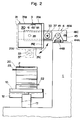
- FIG. 1 and 2 there is a portion of a cigarette packaging machine 1, on which is disposed a plate 10 which can take, under the action of the piston 11, an elevated position as shown in Figure 1 or a low position as in FIG. 2.
- Feeding means 12 for example a conveyor belt, bring a stack 2 of labels 20 for cigarette packs from, for example, a depalletizer for cigarette pack labels such as described in application EP-A-0.354.873, on the plate 10 when the latter is in the low position.
- the labels In order to be accepted for the following operations for forming the packet of cigarettes, the labels must be properly aligned, as represented by the bold line corresponding to the label 20 in FIG. 1.
- the main object of the invention is therefore to propose a method and a device making it possible to realign the labels in the stack 2, so that they are all aligned in a determined position, for example that represented by the label 20
- the device according to the invention is composed of a first pivoting portion 3 held by a second portion able to move longitudinally 4.
- the portion able to move longitudinally is mainly composed of two carrying arms 40 and 41, preferably arranged horizontally, and capable of moving longitudinally by a certain distance, in order to approach or move away from each other , under the action of means which will be described later.
- the pivoting portion 3 is mainly composed of two receiving portions in the form of half-shells 30 and 31, each composed of a support wall 30A, respectively 31A, of an upper wall 30B, respectively 31B, of a wall bottom 30C, respectively 31C and an end wall 30D, respectively 31D.
- each half-shell 30, 31 has the general shape of a rectangular parallelipiped of which two walls of each of the half-shells have been removed, those closest and directly facing the stack 2, thus creating a front opening on each half-shell and two side walls, those which would be opposite the walls support 30A and 31A, thus creating lateral openings.
- Each of the half-shells 30, 31 is fixed to a pivoting arm 32, respectively 33, by its end wall 30D or 31D, each of said arms 32.33 being provided with a pivot 34.35, preferably centered on the center of gravity of each of the half-shells 30 and 31 and pivoting in a bearing 42, respectively 43, arranged in each of the carrying arms 40 and 41.
- the other ends of each of the pivoting arms 32, 33 are preferably connected by a device sliding, consisting for example of a rod 36 sliding inside a tube 37 of which at least a portion is calibrated on the diameter of the rod 36.
- One of the two pivots is extends on the other side of the bearing 42 and is connected to a rotational drive means 38, preferably a pneumatic actuator, capable of driving the half-shell 30, via the pivot 34, then the half shell 31 by means of rod 36 and tube 37, in a rotational movement 90 ° sequential as explained below.
- the body of the actuator 38 is fixed to the support arm 40.
- the actuator 38 has been described as being pneumatically controlled, but it may also be a device with hydraulic or electric drive; just as the second half-shell can be driven by its own actuator, synchronized with the first and which would be arranged symmetrically with the actuator 38 shown, and not by means of the rod 36 and the tube 37.
- each of the support arms 40 and 41 can move longitudinally over a portion of the packaging machine 1, the support arms 40, 41 being able to approach or move away from one another. 'a certain distance. For this, they each rest on a slide 44A moving on a slide 44B between two stops 44C and 44D representing the extreme positions of movement, preferably provided with limit switches.
- the slide 44B can also be provided with another detector 44E signaling a half-closed position as explained below.
- a single slide / slide play has been shown in FIG. 1 in order to facilitate reading, it being understood that the support arm 41 is equipped in the same way. As a variant, it is also possible to have only one slide common to the two support arms 40.
- actuation means which can be, for example example a spring 45, tending to bring the two arms 40 and 41 closer together, which exerts its effect in opposition to a pneumatic or hydraulic device consisting of a cylinder body 46A, fixed to the frame of the machine, in which a piston 46B connected circulates by a rod 46C to the support arm 41.
- actuation means which can be, for example example a spring 45, tending to bring the two arms 40 and 41 closer together, which exerts its effect in opposition to a pneumatic or hydraulic device consisting of a cylinder body 46A, fixed to the frame of the machine, in which a piston 46B connected circulates by a rod 46C to the support arm 41.
- D 'other means can be used to bring these movements of approximation / distance of the two support arms, for example the action of the spring 45 and the cylinders 46A, 46B can be opposite to that described, the spring tending to distance the two br as carriers while the jack is arranged to bring them together; another possibility, visible in FIG. 3, is to provide a double-acting pneumatic or hydraulic cylinder 47; it is thus possible to remove the spring. It is also possible to directly motor the slides 44A, by electro-mechanical means or, as seen in FIG. 4, to provide a device 48 for rotating a rod 49, the ends of the latter comprising reverse threads which are screwed in and out respectively in suitable threads provided in the support arms 40 and 41.
- one of the support arms is fixed to a strand of a belt endless while the other carrying arm is fixed to the other strand of the same belt; by applying a movement of displacement to the belt, one obtains a ruzement, respectively a separation of the two carrying arms.
- the support arms 40, 41 respectively the two half-shells 30 and 31, are separated from each other as much as possible; the two half-shells 30 and 31 are turned so that their lateral opening is directed from the side, either upwards according to the representation in FIG. 1 and to the left according to the representation in solid lines in FIG. 2.
- the plate 10 is in the low position, as shown in FIG. 2.
- a stack 2 which may include one or more misaligned labels 21, 22, 23, is brought by supply means, for example a conveyor belt 12, placed at a height such that the stack 2 can pass underneath the half shell 31.
- the conveyor belt 12 stops when the center of the stack 2 has approximately arrived at the center of the plate 10.
- the latter is then raised, by means of the jack 11, so that the lower surface of the label placed at the very bottom of the stack 2 is very slightly above the plane formed by the two lower walls 30C and 31C of the two half-shells 30 and 31.
- These are then brought together, by the means of longitudinal displacement of the support arms 40 and 41 described above, up to an intermediate or semi-closed position, as shown in Figure 3.
- the horizontal axis along which the stack 2 is transported by the conveyor belt 12 is offset laterally relative to the horizontal axis comprising the center of gravity of the half-shells 30 and 31 , corresponding approximately to the axis connecting the two pivots 34 and 35.
- This distance between these two horizontal axes corresponds to the maximum allowable extent of a lateral offset of a label 22 in the stack 2.
- no part of the labels placed in the stack 2 should for the moment come into contact with any of the parts of the half-shells 30 and 31.
- the distance separating the two internal faces of the upper and lower walls 30B and 30C, respectively 31B and 31c is slightly greater than the height of the stack 2.
- the edges of the p support arois 30A and 31A may include a flare 30E, 31E respectively, which facilitates the introduction of a label whose misalignment is very close, or even slightly greater than the maximum allowable misalignment.
- the pivoting portion 3, respectively the two half-shells 30 and 31 containing the stack 2 then pivots 90 °, around its longitudinal horizontal axis, driven by the actuator 38 as explained above, so that the walls of support 30A and 31A come in the lower position, as shown in FIG. 4 or as visible by a broken line in FIG. 2.
- the labels 20, seen from above in FIG. 4 therefore come to support their lower edge, by gravity, on the support walls 30A and 31A. Since there is a lateral clearance between the labels, originating between the difference between the height of the stack 2 and the distance between the upper and lower walls of each half-shell 30, 31, said walls now being arranged laterally with respect to stack 2, this downward movement can be carried out very freely.
- the labels 22, 23 which had a transverse misalignment are now realigned correctly with respect to the stack 2.
- control unit 5 (see FIG. 1) comprising a central unit 50, itself controlled by the general control of the packaging machine, and acting sequentially on the different drives of the device.
- sensors may be available, for example on the stops 44C and 44D, as well as one or more sensors 38A on the actuator 38, as well as a position sensor 44E on the slide 44B.
- the labels 20 have one printed side while the other side is devoid of printing. It is possible that, during the manipulations intervening earlier in the process, some stacks of labels are completely turned over, that is to say that, if for example the stacks should normally appear with the printed side of the labels facing the high to be properly processed by the cigarette packer, a stack may present from time to time with the label side facing down.
- a detector device 6 preferably composed of a transmitter 60 and a receiver 61, preferably arranged in the same housing (see Figures 1 and 2).
- the transmitter 60 will preferably be a transmitter of light radiation, directed towards the battery 2, the receiver 61 being adapted; the light ray which has been emitted by the emitter 60 and then reflected by a surface of the label arranged nearby to return to the detector 61 will have a different intensity depending on whether said surface is printed or white.
- This signal is then sent to the central control unit 50 which, when the labels 20 have all been aligned as described above, will control the pivoting of the pivoting portion 3 according to the intensity of the signal received, ie for a return to its initial position, in case the stack is correctly oriented, or for an additional pivoting of 90 ° in order to present it in an inverted position of that according to which the stack 2 was presented at the entrance of the device, so that the stack 2 is oriented properly for the further processing of the labels.
- the alignment device has been described according to a preferred embodiment, but it is obvious that other modes of construction can be envisaged; in particular, it is not necessary for the carrying arms 40 and 41 to be horizontal, they can also be arranged obliquely or then vertically. A person skilled in the art will know how to design the slides and slides 44A and 44B so that the device does not tip over. It is also not absolutely necessary that the walls of the half-shells are full as shown in the figures, they can also be perforated.
- the means of transporting the batteries have been described as consisting in particular of two conveyor belts bringing, respectively discharging, the stacks of labels.
- the method and the device according to the invention make it possible to easily reach the set goals, that is to quickly and efficiently realign drafts or misaligned labels as well as to reorient a misaligned stack.
- Another advantage of the device is that, given its relatively simple design and small footprint, it is entirely possible to integrate it on an existing packaging machine in order to considerably improve its performance by reducing downtime. due to stuck label.
Landscapes
- Engineering & Computer Science (AREA)
- Mechanical Engineering (AREA)
- Wrapping Of Specific Fragile Articles (AREA)
- Making Paper Articles (AREA)
Claims (11)
- Verfahren zum Ausrichten von Verpackungszuschnitten ("Ebauches") , besonders von Etiketten für Zigarettenpackungen, welche in einem Stapel angeordnet sind,
bestehend aus den folgenden Schritten:
Zufuhr eines Stapels (2), der aus einem oder mehreren schlecht ausgerichteten Zuschnitten (21, 22, 23) besteht, mithilfe von Transportmitteln (10, 12), wobei die genannten Zuschnitte in der horizontalen Ebene angeordnet sind, derart, dass jedes der vorderen und hinteren Enden der genannten Zuschnitte gegenüber einer Frontöffnung eines Aufnahmeabschnittes in der Form eines Halbgehäuses (30, 31) angeordnet ist, wobei der Abstand zwischen den zwei Frontöffnungen grösser als die Stapellänge ist,
Annäherung der zwei Halbgehäuse (30, 31) bis in eine Stellung, in der ein Abschnitt eines jeden Endes der unteren Oberfläche des sich unten im Stapel befindenden Zuschnittes durch einen Oberflächenabschnitt einer unteren Wand (30C, 31C) jedes Halbgehäuses getragen wird,
Zurückzug der genannten Transportmittel,
erstes Abdrehen um 90° der zwei Halbgehäuse bzw. des Stapels mit Zuschnitten um eine horizontale Längsachse, wobei sich alle Zuschnitte des Stapels mit einem Abschnitt ihrer Schnittfläche auf einer Andrückwand (30A, 31A), die im unteren Bereich jedes Halbgehäuses angeordnet ist, derart abstützen, dass die in Querrichtung schlecht ausgerichteten Zuschnitte (22, 23) ausgerichtet werden, wobei die seitwärts abgedrehten Abschnitte der oberen und unteren Oberflächen des Stapels durch Abschnitte von oberen und unteren Wänden (30B, 30C, 31B, 31C) der Halbgehäuse festgehalten werden,
Annäherung der zwei Halbgehäuse, wobei deren Endwände (30D, 31D) derart auf die in Längsrichtung nicht ausgerichteten Zuschnitt-Enden (21, 23) drücken, dass diese vollständig in den Stapel eingeschoben werden,
zweites Abdrehen um 90° der zwei Halbgehäuse bzw. des Stapels mit Zuschnitten um die horizontale Längsachse,
Entfernung der zwei Halbgehäuse bis in eine Stellung, in der der Stapel für ein Ergreifen durch die Transportmittel (10) zugänglich ist,
Annäherung der Transportmittel bis sie den Stapel mit Zuschnitten ergreifen,
vollständige Entfernung der zwei Halbgehäuse, so dass die vorderen und hinteren Stapelenden von ihnen freigegeben werden,
Entleerung des Stapels mit ausgerichteten Zuschnitten durch die Transportmittel (10, 13), für ihre weitere Verarbeitung. - Verfahren nach Anspruch 1, dadurch gekennzeichnet, dass eine Oszillationsbewegung auf die Halbgehäuse bzw. auf den Stapel mit Zuschnitten gegeben wird, wenn die letzteren auf ihrer Schnittfläche aufliegen.
- Verfahren nach einem der vorangehenden Ansprüche, dadurch gekennzeichet, dass eine Erkennung der Ausrichtung des Stapels mit Zuschnitten erfolgt und dass, abhängig von dem aus dieser Erkennung resultierenden Signal, das zweite Abdrehen um 90° derart in der einen oder anderen Richtung erfolgt, dass die Stapel immer auf die gleiche Art ausgerichtet werden.
- Anordnung zum Ausrichten von Verpackungszuschnitten ("Ebauches"), besonders von Etiketten für Zigarettenpackungen, für die Anwendung des Verfahrens nach Anspruch 1, besonders bestehend aus Transportmitteln (10, 12, 13), die das Zuführen bzw. das Entleeren eines Stapels mit Zuschnitten durch Ergreifen bzw. durch Zurückziehen aus der genannten Anordnung erlauben, und aus Stapel-Aufnahmemitteln in der Form von Halbgehäusen (30, 31),
dadurch gekennzeichnet, dass sie im weitern enthält:
zwei Tragarme (40, 41), welche parallel angeordnet sind, wobei das eine Ende von beiden mit Mitteln (44A, 44B, 45, 46A, 46B; 47; 48, 49) versehen ist, die ein Längsverschieben für eine Annäherung oder Entfernung der genannten Arme erlauben, und das andere Ende von beiden mit einem Lager (42, 43) versehen ist, wobei die zwei Lager in einer senkrecht zu den zwei Tragarmen stehenden, horizontalen Längsachse ausgerichtet sind,
zwei Aufnahmeabschnitte in Form von Halbgehäusen (30, 31), wobei jeder davon eine Endwand (30D, 31D), eine Andrückwand (30A, 31A), eine obere Wand (30B, 31B) und eine untere Wand (30C, 31C) enthält, wobei die genannten Wände eine im wesentlichen rechteckige Form aufweisen, die Endwände senkrecht zur genannten horizontalen Längsachse angeordnet sind, die anderen Wände von jedem Halbgehäuse senkrecht an drei Rändern der Endwand befestigt sind und an jedem Halbgehäuse eine Frontöffnung und eine Seitenöffnung definieren, wobei die zwei Frontöffnungen einander gegenüberliegen und die zwei Seitenöffnungen in die gleiche Richtung ausgerichtet sind, während ein Drehzapfen (34, 35) senkrecht mit der Endwand von jedem Halbgehäuse an einer ungefähr zentralen Stelle an ihren Aussenseiten verbunden ist, wobei die genannten Drehzapfen in die genannten Lager eingreifen,
Drehantriebsmittel (38, 36, 37), die dafür ausgelegt sind, die zwei Halbgehäuse auf synchronisierte Weise um die genannte horizontale Achse drehen zu lassen. - Anordnung nach Anspruch 4, dadurch gekennzeichnet, dass die Längsachse zur Verschiebung des Stapels auf den Zufuhr-Transportmitteln (12) bezogen auf die horizontale Längsdrehachse in Querrichtung verschoben ist, und zwar in Richtung der Seitenöffnung von jedem Halbgehäuse und um einen Betrag, der mindestens gleich demjenigen des grössten zulässigen seitlichen Ausrichtfehlers eines Zuschnittes in einem Stapel mit nicht ausgerichteten Zuschnitten ist.
- Anordnung nach einem der Ansprüche 4 oder 5, dadurch gekennzeichnet, dass mindestens eine Wand von jedem Halbgehäuse eine Ausweitung (30E, 31E) enthält, die gegen die Aussenseite des Halbgehäuses gerichtet und am äusseren Rand der genannten Wand angeordnet ist.
- Anordnung nach einem der Ansprüche 4 bis 6, dadurch gekennzeichnet, dass die Drehantriebsmittel aus einem einzigen Aktuator (38) gebildet werden, der den Drehzapfen (34) antreibt, welcher mit einem ersten Halbgehäuse (30) verbunden ist, während das zweite Halbgehäuse (31) angetrieben wird durch einen ersten Dreharm (32), der an der Endwand (30D) des ersten Halbgehäuses befestigt ist, sowie durch einen zweiten Dreharm (33), der mit der Endwand (31D) des zweiten Halbgehäuses (31) verbunden ist, wobei die zwei Dreharme mitttels einer Kupplung (36, 37) verbunden sind, die in der Lage ist, sich zu verlängern oder zu verkürzen.
- Anordnung nach einem der Ansprüche 4 bis 7, dadurch gekennzeichnet, dass die Drehantriebsmittel (38) geeignet sind, eine Oszillationsbewegung auf den Stapel mit den Zuschnitten zu geben, wenn dieser auf seiner Schnittfläche liegt.
- Anordnung nach einem der Ansprüche 4 bis 8, dadurch gekennzeichnet, dass sie im weitern Erkennungsmittel (60, 61) für die Ausrichtung des Stapels mit Zuschnitten enthält, wobei die genannten Erkennungsmittel ein Signal liefern, das geeignet ist, die Richtung festzulegen, in welcher das zweite Abdrehen um 90° des Stapels mit Zuschnitten erfolgt.
- Anordnung nach einem der Ansprüche 4 bis 9, dadurch gekennzeichnet, dass sie eine Steuereinheit (50) enthält, die geeignet ist, Signale von Fühlern (38A, 44C, 44D, 44E) zu empfangen, und die geeignet ist zur sequentiellen Steuerung der Längsverschiebungs- oder der Drehbewegungen der Halbgehäuse.
- Zigaretten-Verpackungsmaschine, dadurch gekennzeichnet, dass sie mit einer Anordnung nach einem der Ansprüche 4 bis 10 ausgerüstet ist.
Priority Applications (3)
| Application Number | Priority Date | Filing Date | Title |
|---|---|---|---|
| DE69200042T DE69200042T2 (de) | 1992-07-06 | 1992-07-06 | Verfahren und Vorrichtung zum Ausrichten von Verpackungszuschnitten, insbesondere Etiketten für Zigarettenpackungen. |
| EP92810517A EP0577905B1 (de) | 1992-07-06 | 1992-07-06 | Verfahren und Vorrichtung zum Ausrichten von Verpackungszuschnitten, insbesondere Etiketten für Zigarettenpackungen |
| US08/080,761 US5302079A (en) | 1992-07-06 | 1993-06-24 | Apparatus and method for aligning packaging blanks |
Applications Claiming Priority (1)
| Application Number | Priority Date | Filing Date | Title |
|---|---|---|---|
| EP92810517A EP0577905B1 (de) | 1992-07-06 | 1992-07-06 | Verfahren und Vorrichtung zum Ausrichten von Verpackungszuschnitten, insbesondere Etiketten für Zigarettenpackungen |
Publications (2)
| Publication Number | Publication Date |
|---|---|
| EP0577905A1 EP0577905A1 (de) | 1994-01-12 |
| EP0577905B1 true EP0577905B1 (de) | 1994-01-19 |
Family
ID=8211949
Family Applications (1)
| Application Number | Title | Priority Date | Filing Date |
|---|---|---|---|
| EP92810517A Expired - Lifetime EP0577905B1 (de) | 1992-07-06 | 1992-07-06 | Verfahren und Vorrichtung zum Ausrichten von Verpackungszuschnitten, insbesondere Etiketten für Zigarettenpackungen |
Country Status (3)
| Country | Link |
|---|---|
| US (1) | US5302079A (de) |
| EP (1) | EP0577905B1 (de) |
| DE (1) | DE69200042T2 (de) |
Families Citing this family (11)
| Publication number | Priority date | Publication date | Assignee | Title |
|---|---|---|---|---|
| IT1258021B (it) * | 1992-07-28 | 1996-02-20 | Gd Spa | Metodo per il prelievo di pile di sbozzati |
| FR2754802B1 (fr) * | 1996-10-22 | 1998-11-27 | Cetra Packaging | Procede et installation pour l'organisation et le rangement de piles de cartonnettes, notamment des etuis a cigarettes, en vue de leur palettisation |
| DE19728515A1 (de) * | 1997-07-04 | 1999-01-07 | Focke & Co | Verfahren und Vorrichtung zum Herstellen von Klappschachteln für Zigaretten |
| DE19904443A1 (de) * | 1999-02-04 | 2000-08-10 | Hauni Maschinenbau Ag | Verfahren und Vorrichtung zum Zuführen von Packungszuschnitten |
| DE19939164B4 (de) * | 1999-08-20 | 2005-02-10 | Koenig & Bauer Ag | Verfahren zur Verarbeitung von Bedruckstoffen |
| US6524058B1 (en) * | 2000-11-02 | 2003-02-25 | Robert Watters | Assembly and method for stacking, conveying and lifting lids |
| US7204362B2 (en) * | 2003-12-30 | 2007-04-17 | National Conveyor Corporation | Automatic tray repositioning device |
| NZ533533A (en) | 2004-06-11 | 2006-11-30 | Avalon Engineering Ltd | Deployment method and apparatus for moving stacked articles in varying orientations |
| US8702089B2 (en) | 2011-07-22 | 2014-04-22 | Bell and Howell, LLC. | Method and system to feed inserts with a rotary and gripper system |
| DE102020103398A1 (de) * | 2020-02-11 | 2021-08-12 | Heidelberger Druckmaschinen Aktiengesellschaft | Verfahren zum Bewegen eines Produktstapels mit einem Roboter |
| AT527899A1 (de) * | 2023-12-20 | 2025-07-15 | Pamminger Verpackungstechnik Ges M B H | Vorrichtung zum Ausrichten eines Profilstapels |
Family Cites Families (6)
| Publication number | Priority date | Publication date | Assignee | Title |
|---|---|---|---|---|
| GB1406251A (en) * | 1972-02-10 | 1975-09-17 | Deritend Eng Co | Feeders for sheet material |
| GB1325288A (en) * | 1972-02-29 | 1973-08-01 | Pentacon Dresden Veb | Alignment device for sheet material |
| DE2224107A1 (de) * | 1972-05-17 | 1973-12-06 | Bhs Bayerische Berg | Vorrichtung zur bearbeitung von papierstapeln in zusammenarbeit mit planschneidmaschinen |
| US4700941A (en) * | 1986-05-22 | 1987-10-20 | Thermoguard Equipment Inc. | Corrugated sheet unstacking and feeding apparatus |
| EP0444626A3 (en) * | 1990-03-01 | 1992-03-04 | Industria Grafica Meschi S.R.L. | Automatic service apparatus for fast printers, particularly laser printer |
| US5039081A (en) * | 1990-05-11 | 1991-08-13 | Thermoguard Equipment, Inc. | Squaring and aligning assembly for a corrugated sheet unstacking and feeding apparatus |
-
1992
- 1992-07-06 DE DE69200042T patent/DE69200042T2/de not_active Expired - Fee Related
- 1992-07-06 EP EP92810517A patent/EP0577905B1/de not_active Expired - Lifetime
-
1993
- 1993-06-24 US US08/080,761 patent/US5302079A/en not_active Expired - Fee Related
Also Published As
| Publication number | Publication date |
|---|---|
| DE69200042D1 (de) | 1994-03-31 |
| EP0577905A1 (de) | 1994-01-12 |
| DE69200042T2 (de) | 1994-07-14 |
| US5302079A (en) | 1994-04-12 |
Similar Documents
| Publication | Publication Date | Title |
|---|---|---|
| EP0530426B1 (de) | Greif- und Übertragungszange | |
| EP4234457B1 (de) | Palettengreifer | |
| EP0577905B1 (de) | Verfahren und Vorrichtung zum Ausrichten von Verpackungszuschnitten, insbesondere Etiketten für Zigarettenpackungen | |
| EP0927136B1 (de) | Vorrichtung zum ausgeben von paletten | |
| FR2511352A1 (fr) | Appareil pour separer des feuilles dans un organe d'empilage alimente en feuilles en continu | |
| FR3005456A1 (fr) | Dispositif d'alimentation en sacs d'emballage dans une machine d'emballage | |
| FR2642039A1 (fr) | Procede et dispositif d'alimentation en continu de flans | |
| FR2976561A1 (fr) | Distributeur de flancs a plat. | |
| FR2639905A1 (fr) | Machine notamment encartonneuse, pour mettre automatiquement un article, en particulier un flacon, dans un etui | |
| EP0251833B1 (de) | Einrichtung zur zeitweisen Einlagerung von flachen Gegenständen | |
| CH373688A (fr) | Procédé pour insérer une ébauche de séparation pliable entre des rangées de récipients à emballer et machine pour la mise en oeuvre de ce procédé | |
| FR2729376A1 (fr) | Dispositif distributeur de barquettes | |
| EP3263469A1 (de) | Maschine zum extrahieren, auffalten, füllen und schliessen einer faltschachtel | |
| FR2781776A1 (fr) | Procede et dispositif pour entreposer et transferer des marchandises | |
| FR3125452A1 (fr) | Outil de préhension de caisse et système de palettisation et/ou de dépalettisation le comprenant | |
| EP0693446A1 (de) | Handhabungsvorrichtung für Schalen | |
| EP0267431A1 (de) | Einrichtung zum Stapeln von flachen Gegenständen | |
| EP0425323B1 (de) | Verfahren und Vorrichtung zur axialen und einseitig gerichteten Orientierung von buchsenförmigen Stücken mit einer transversalen Endwand | |
| FR2494213A1 (fr) | Dispositif pour emballer des piles de papier dans des cartons preformes | |
| FR3151235A1 (fr) | Préhenseur à formage de caisse en carton, bras robotisé associé et dispositifs de formage et de remplissage de caisse en carton associés | |
| EP0562197B1 (de) | Verfahren und Vorrichtung zum Palettieren von Paketen | |
| EP2363281A1 (de) | Maschine zum Bekleiden das Innere von Verpackungskartons mit Plastiksäcken | |
| FR2493806A1 (fr) | Procede et machine pour constituer un contenant de forme generale parallelepipedique a partir d'une forme aplatie et introduite dans le contenant un contenu | |
| FR2804654A1 (fr) | Installation d'ensachage comportant plusieurs magasins a sacs | |
| FR2686531A1 (fr) | Dispositif de manipulation de cartes, notamment d'informations publicitaires et machine d'empilage de cartes comportant un tel dispositif. |
Legal Events
| Date | Code | Title | Description |
|---|---|---|---|
| PUAI | Public reference made under article 153(3) epc to a published international application that has entered the european phase |
Free format text: ORIGINAL CODE: 0009012 |
|
| GRAA | (expected) grant |
Free format text: ORIGINAL CODE: 0009210 |
|
| 17P | Request for examination filed |
Effective date: 19921204 |
|
| AK | Designated contracting states |
Kind code of ref document: A1 Designated state(s): BE CH DE FR GB IT LI NL |
|
| AK | Designated contracting states |
Kind code of ref document: B1 Designated state(s): BE CH DE FR GB IT LI NL |
|
| REF | Corresponds to: |
Ref document number: 69200042 Country of ref document: DE Date of ref document: 19940331 |
|
| GBT | Gb: translation of ep patent filed (gb section 77(6)(a)/1977) |
Effective date: 19940308 |
|
| ITF | It: translation for a ep patent filed | ||
| PLBE | No opposition filed within time limit |
Free format text: ORIGINAL CODE: 0009261 |
|
| 26N | No opposition filed | ||
| REG | Reference to a national code |
Ref country code: GB Ref legal event code: IF02 |
|
| PGFP | Annual fee paid to national office [announced via postgrant information from national office to epo] |
Ref country code: FR Payment date: 20040610 Year of fee payment: 13 |
|
| PGFP | Annual fee paid to national office [announced via postgrant information from national office to epo] |
Ref country code: CH Payment date: 20040611 Year of fee payment: 13 |
|
| PGFP | Annual fee paid to national office [announced via postgrant information from national office to epo] |
Ref country code: NL Payment date: 20040614 Year of fee payment: 13 Ref country code: GB Payment date: 20040614 Year of fee payment: 13 |
|
| PGFP | Annual fee paid to national office [announced via postgrant information from national office to epo] |
Ref country code: DE Payment date: 20040621 Year of fee payment: 13 |
|
| PGFP | Annual fee paid to national office [announced via postgrant information from national office to epo] |
Ref country code: BE Payment date: 20040713 Year of fee payment: 13 |
|
| PG25 | Lapsed in a contracting state [announced via postgrant information from national office to epo] |
Ref country code: IT Free format text: LAPSE BECAUSE OF NON-PAYMENT OF DUE FEES;WARNING: LAPSES OF ITALIAN PATENTS WITH EFFECTIVE DATE BEFORE 2007 MAY HAVE OCCURRED AT ANY TIME BEFORE 2007. THE CORRECT EFFECTIVE DATE MAY BE DIFFERENT FROM THE ONE RECORDED. Effective date: 20050706 Ref country code: GB Free format text: LAPSE BECAUSE OF NON-PAYMENT OF DUE FEES Effective date: 20050706 |
|
| PG25 | Lapsed in a contracting state [announced via postgrant information from national office to epo] |
Ref country code: LI Free format text: LAPSE BECAUSE OF NON-PAYMENT OF DUE FEES Effective date: 20050731 Ref country code: CH Free format text: LAPSE BECAUSE OF NON-PAYMENT OF DUE FEES Effective date: 20050731 Ref country code: BE Free format text: LAPSE BECAUSE OF NON-PAYMENT OF DUE FEES Effective date: 20050731 |
|
| PG25 | Lapsed in a contracting state [announced via postgrant information from national office to epo] |
Ref country code: NL Free format text: LAPSE BECAUSE OF NON-PAYMENT OF DUE FEES Effective date: 20060201 Ref country code: DE Free format text: LAPSE BECAUSE OF NON-PAYMENT OF DUE FEES Effective date: 20060201 |
|
| REG | Reference to a national code |
Ref country code: CH Ref legal event code: PL |
|
| GBPC | Gb: european patent ceased through non-payment of renewal fee |
Effective date: 20050706 |
|
| PG25 | Lapsed in a contracting state [announced via postgrant information from national office to epo] |
Ref country code: FR Free format text: LAPSE BECAUSE OF NON-PAYMENT OF DUE FEES Effective date: 20060331 |
|
| NLV4 | Nl: lapsed or anulled due to non-payment of the annual fee |
Effective date: 20060201 |
|
| REG | Reference to a national code |
Ref country code: FR Ref legal event code: ST Effective date: 20060331 |
|
| BERE | Be: lapsed |
Owner name: S.A. FABRIQUES DE *TABAC REUNIES Effective date: 20050731 |