EP0578128A1 - Cylindre de plastification d'une machine à mouler par injection de matières plastiques - Google Patents
Cylindre de plastification d'une machine à mouler par injection de matières plastiques Download PDFInfo
- Publication number
- EP0578128A1 EP0578128A1 EP93110486A EP93110486A EP0578128A1 EP 0578128 A1 EP0578128 A1 EP 0578128A1 EP 93110486 A EP93110486 A EP 93110486A EP 93110486 A EP93110486 A EP 93110486A EP 0578128 A1 EP0578128 A1 EP 0578128A1
- Authority
- EP
- European Patent Office
- Prior art keywords
- nozzle body
- plasticizing cylinder
- adapter
- diameter
- space
- Prior art date
- Legal status (The legal status is an assumption and is not a legal conclusion. Google has not performed a legal analysis and makes no representation as to the accuracy of the status listed.)
- Ceased
Links
- 238000001746 injection moulding Methods 0.000 title claims abstract description 5
- 229920003023 plastic Polymers 0.000 title claims abstract description 4
- 239000004033 plastic Substances 0.000 title claims abstract description 4
- 230000007704 transition Effects 0.000 claims abstract description 16
- 238000002347 injection Methods 0.000 claims abstract description 3
- 239000007924 injection Substances 0.000 claims abstract description 3
- 239000007921 spray Substances 0.000 claims description 11
- 230000001154 acute effect Effects 0.000 claims description 3
- 230000001681 protective effect Effects 0.000 description 5
- 239000000463 material Substances 0.000 description 4
- 238000012549 training Methods 0.000 description 3
- 230000008859 change Effects 0.000 description 2
- 238000013461 design Methods 0.000 description 2
- 239000007789 gas Substances 0.000 description 2
- 238000010438 heat treatment Methods 0.000 description 2
- 238000004519 manufacturing process Methods 0.000 description 2
- 238000003825 pressing Methods 0.000 description 2
- 238000012545 processing Methods 0.000 description 2
- 230000000717 retained effect Effects 0.000 description 2
- 239000000919 ceramic Substances 0.000 description 1
- 238000004140 cleaning Methods 0.000 description 1
- 238000010276 construction Methods 0.000 description 1
- 238000001816 cooling Methods 0.000 description 1
- 230000007797 corrosion Effects 0.000 description 1
- 238000005260 corrosion Methods 0.000 description 1
- 238000001125 extrusion Methods 0.000 description 1
- 230000007246 mechanism Effects 0.000 description 1
- 238000000034 method Methods 0.000 description 1
- 230000035515 penetration Effects 0.000 description 1
- 230000008569 process Effects 0.000 description 1
- 238000007493 shaping process Methods 0.000 description 1
Images
Classifications
-
- B—PERFORMING OPERATIONS; TRANSPORTING
- B29—WORKING OF PLASTICS; WORKING OF SUBSTANCES IN A PLASTIC STATE IN GENERAL
- B29C—SHAPING OR JOINING OF PLASTICS; SHAPING OF MATERIAL IN A PLASTIC STATE, NOT OTHERWISE PROVIDED FOR; AFTER-TREATMENT OF THE SHAPED PRODUCTS, e.g. REPAIRING
- B29C45/00—Injection moulding, i.e. forcing the required volume of moulding material through a nozzle into a closed mould; Apparatus therefor
- B29C45/17—Component parts, details or accessories; Auxiliary operations
- B29C45/46—Means for plasticising or homogenising the moulding material or forcing it into the mould
- B29C45/58—Details
-
- B—PERFORMING OPERATIONS; TRANSPORTING
- B29—WORKING OF PLASTICS; WORKING OF SUBSTANCES IN A PLASTIC STATE IN GENERAL
- B29C—SHAPING OR JOINING OF PLASTICS; SHAPING OF MATERIAL IN A PLASTIC STATE, NOT OTHERWISE PROVIDED FOR; AFTER-TREATMENT OF THE SHAPED PRODUCTS, e.g. REPAIRING
- B29C45/00—Injection moulding, i.e. forcing the required volume of moulding material through a nozzle into a closed mould; Apparatus therefor
- B29C45/17—Component parts, details or accessories; Auxiliary operations
- B29C45/20—Injection nozzles
Definitions
- the invention relates to a plasticizing cylinder on a plastic injection molding machine according to the preamble of claim 1.
- Such a plasticizing cylinder is known for example from DE-PS 41 05 731.
- plasticizing cylinders with a different inside diameter to be used for different diameters of screw conveyors. Since the diameter at the transition to the nozzle body is designed as a function of the diameter of the screw conveyor in order to ensure a continuous lateral surface, in particular in the transition area, it is necessary that only one nozzle body is assigned to each plasticizing cylinder. Each time the plasticizing cylinder is changed, the nozzle body must therefore also be replaced, which contributes considerably to the increase in costs, since an associated nozzle body must always be provided with a plasticizing cylinder.
- a connecting sleeve enclosing the plasticizing cylinder in the area of the nozzle and partially axially overlapping the nozzle body is fastened to the plasticizing cylinder, the threaded bolts being in engagement with internal threads of the connecting sleeve and thereby being axially supported, so that they can attack on the pressing surfaces of the nozzle body on the front.
- the invention has for its object to develop a plasticizing cylinder of the type mentioned in such a way that the nozzle body does not necessarily have to be replaced when changing the plasticizing cylinder.
- the nozzle body still has to be removed from the plasticizing cylinder, after replacing the plasticizing cylinder, the nozzle body can be put back on the replaced plasticizing cylinder. It is essential that an adapter is provided between the end diameter of the interior of the plasticizing cylinder receiving the screw conveyor and the inlet diameter of the nozzle body, which converts the two edge sizes into one another. This creates the basic prerequisites for the fact that the same nozzle body can be used in a large number of plasticizing cylinders with different inner diameters, so that both the costs and the space required by the buyer of the injection molding machine can be reduced, which are otherwise necessary Variety of nozzle bodies are caused.
- the adapter is assigned to the nozzle body or the plasticizing cylinder and whether it is limited to an area adjacent to the inner diameter or whether it extends into the outer area of the nozzle body and plasticizing cylinder and is overlapped there, for example, by a connecting sleeve .
- the basic prerequisites are created to leave the drive mechanisms for a closure nozzle unchanged, so that the adapter can be used both with closure nozzles and with open nozzles.
- an adapter ring is provided as an adapter, which is arranged on the nozzle body and is held there in a circular recess.
- the circular recess only has to be created on the nozzle body and not on a large number of plasticizing cylinders.
- the inlet diameter of the nozzle body is determined so that it is smaller than the diameter of even a small screw conveyor for the large number of cases in order to avoid widening of the space exposed to high pressures.
- the points of attack for possible "caking" are reduced by constructive measures.
- the depth of the recess is slightly less than the thickness of the adapter ring, so that when the nozzle body is pressed onto the plasticizing cylinder, the connection between the adapter ring and the pressed parts is first created, so that no gaps are thereby created may remain between the parts to be joined, into which material or corrosive gases could penetrate, which can cause the parts clamped to one another to solidify particularly at high temperatures. It should be noted that materials are being processed in the ceramic sector, the higher temperatures, now and in the future make necessary.
- the transitions are also held perpendicular to the transition surfaces, on the one hand to facilitate processing during manufacture, and on the other hand to facilitate detachability, since in such an arrangement the abutting end surfaces of the parts to be connected are always perpendicular to the lateral surface, so that the probability of material penetration is reduced to a minimum.
- a training according to claims 8 and 9 creates the basic requirements that are required to perform a quick removal of the nozzle body from the plasticizing cylinder to be replaced.
- the force that has to be exerted to press the parts against one another is reduced by the large number of threaded bolts, and on the other hand, the threaded bolts are arranged in an area that is not as exposed to the heat and to the corrosion processes as an inner one lying area.
- the prerequisites for a modular system according to an embodiment are created, so that a large number of different plasticizing cylinders can be built from a few parts, the remaining parts provided on the machine, such as e.g. the drive units for the nozzle needle as well as the nozzle needle and thermal sensor can be retained in unchanged form. In principle, it is no longer necessary to separate such parts from the nozzle body.
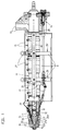
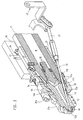
- FIG. 1 shows the plasticizing cylinder 11, which is received on the back by a carrier block 10 and is enclosed by a protective skeleton A.
- the plasticizing cylinder protrudes from the front of the protective skeleton.
- the protective skeleton comprises socket elements 29, 29 'which receive the plasticizing cylinder 11 in bores and carry protective plates 15 which enclose the plasticizing cylinder in the central section with a rectangular cross section.
- the protective skeleton also includes rails 18 with which the plasticizing cylinder is supported on stationary rollers for moving up to the injection mold.
- the plasticizing cylinder is provided with a nozzle body 12, the nozzle needle 13 of which terminates the nozzle mouth 12a and extends at an acute angle to the spray axis a-a.
- a hydraulic drive cylinder 14 for displacing the nozzle needle 13 into its closed or open position is arranged in the region of the carrier block 10.
- the nozzle needle 13 is actuated by the drive unit 14 via rod-shaped elements 28, 21, a pivot lever 17 being pivotable about an axis 24, which carries the force-transmitting bridge consisting of the rod-shaped elements.
- a cylindrical space R is provided in the interior of the plasticizing cylinder, in which the screw conveyor is rotatably arranged.
- the inner diameter d, d 'of this space R corresponds approximately to the diameter of the cylinder bore.
- This inside diameter tapers from the inside diameter d at the end of the plasticizing cylinder inside the nozzle body to the clear width of the nozzle channel 16 or the nozzle mouth 12a.
- a space is now provided for the spatial fixing of an adapter with a passage opening located transversely to the spray axis, which transfers the inside diameter of the space R to the inlet diameter e of the nozzle body 12.
- the inlet diameter e of the nozzle body is basically like this chosen that for the multitude of cases it is smaller than the inside diameter d of the space R even with the smallest screw conveyor 31.
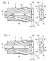
- FIGS. 3 and 4 An adapter ring 34, 34 'is provided as an adapter. From FIGS. 3 and 4, two different adapter rings result from an identical nozzle body 12.
- the adapter ring of FIG. 3 is provided for a screw conveyor 31 with a larger diameter than the adapter ring of FIG. 4. It can clearly be seen from a comparison of FIGS. 3 and 4 that the space R is lengthened by the adapter ring as the screw conveyor becomes smaller, since the transition from the different inner diameters d, d 'to the inlet diameter e of the nozzle body 12 takes place in the region of the adapter ring which is directly adjacent to the nozzle body.
- Figures 3 and 4 differ only with regard to the adapter ring 34 and 34 ', identical parts of the adapter ring are generally identified by the same reference numerals and similar parts are each distinguished by a prime.
- the opening 34a, 34a 'facing the plasticizing cylinder 11 corresponds to the inside diameter d, d' of the space R and thus roughly corresponds to the diameter of the screw conveyor 31 or the cylinder bore and the opening 34b, 34b 'of the adapter ring 34 facing the nozzle body 12, 34 'the inlet diameter e of the nozzle body 12.
- a circular recess 12d is provided on the nozzle body 12 as a space for fixing the adapter ring, which is arranged symmetrically to the spray axis aa.
- the space for fixing the adapter on the plasticizing cylinder 11 or to guide the adapter ring into the outer area of the plasticizing cylinder 11 or nozzle body 12, where it is then overlapped or penetrated by the connecting elements between the plasticizing cylinder and the nozzle body.
- the circular recess 12d is located between two acute angles to the spray axis aa arranged bores 12b, 12e, which are intended for receiving nozzle needle 13 and thermal sensor 35.
- the depth t of the recess 12d is slightly smaller than the thickness s, s 'of the adapter ring 34,34', so that when the nozzle body and plasticizing cylinder 11 are pressed together, an intimate connection between the three parts to be connected, nozzle body 12, adapter ring 34, 34 'and plasticizing cylinder 11 takes place.
- edges 11b, 34c, 34c ', 34d, 34d', 12f ' are provided on the transition surfaces to the respective end surfaces 12g, 34e, 34f, 34e', 12g ', which are perpendicular to the transition surfaces.
- the adapter ring has bevels 34g on the end faces 34e, 34e 'facing the nozzle body.
- the connection of the nozzle body 12 and the plasticizing cylinder 11 takes place, as is known from the older patent application P 41 05 731, via a multiplicity of threaded bolts 26a which, together with a connecting sleeve 26, ensure the connection of the two parts.
- the connecting sleeve 26 surrounds the nozzle body and partially overlaps it and is fastened with a thread to the plasticizing cylinder 11, which in turn has a corresponding external thread.
- the threaded bolts are on the connecting sleeve 26 26a axially supported and engage there in corresponding threads.
- the threaded bolts 26a engage in pressing surfaces on the nozzle body, so that when the threaded bolts are tightened, the nozzle body is pressed against the plasticizing cylinder.
- the thread connection between the connecting sleeve and the plasticizing cylinder which cannot be released when changing the nozzle, represents a thermal bridge, the temperature in the area of the threaded bolts is below the relatively high temperature in the nozzle body and plasticizing cylinder. Since the threaded bolts are much shorter than with conventional connections, corrosive gases cannot cause any damage, as is common with known plasticizing cylinders. Due to the large number of threaded bolts 26a, the nozzle body can be exchanged with a considerably lower amount of physical force and with light and easy-to-use tools. The assembly or service personnel can therefore carry the tool in a briefcase.
- any connections between the nozzle body and the plasticizing cylinder can be provided.
- the connecting elements on the plasticizing cylinder for connecting the nozzle body 12 are always identical.
- the conditions for a modular system or a modular structure of a plasticizing cylinder are thus created, at least one nozzle body 12 with connecting elements for connection to a plasticizing cylinder, plasticizing cylinder 11 with different inside diameters d, d ', but identical end elements for the nozzle body 12 and the front adapter rings assigned to the respective plasticizing cylinder 11 are provided, which convert the different inner diameters d, d 'to the inlet diameter e of the nozzle body 12.
- Identical heating jackets 27, 27a can always be assigned to the plasticizing cylinder 11 and the nozzle body 12.
Landscapes
- Engineering & Computer Science (AREA)
- Manufacturing & Machinery (AREA)
- Mechanical Engineering (AREA)
- Injection Moulding Of Plastics Or The Like (AREA)
- Extrusion Moulding Of Plastics Or The Like (AREA)
Applications Claiming Priority (2)
| Application Number | Priority Date | Filing Date | Title |
|---|---|---|---|
| DE4222432 | 1992-07-09 | ||
| DE4222432A DE4222432C2 (de) | 1992-07-09 | 1992-07-09 | Plastifizierzylinder an einer Kunststoff-Spritzgießmaschine |
Publications (1)
| Publication Number | Publication Date |
|---|---|
| EP0578128A1 true EP0578128A1 (fr) | 1994-01-12 |
Family
ID=6462762
Family Applications (1)
| Application Number | Title | Priority Date | Filing Date |
|---|---|---|---|
| EP93110486A Ceased EP0578128A1 (fr) | 1992-07-09 | 1993-07-01 | Cylindre de plastification d'une machine à mouler par injection de matières plastiques |
Country Status (5)
| Country | Link |
|---|---|
| US (1) | US5375993A (fr) |
| EP (1) | EP0578128A1 (fr) |
| JP (1) | JPH0790581B2 (fr) |
| CA (1) | CA2099085A1 (fr) |
| DE (1) | DE4222432C2 (fr) |
Families Citing this family (3)
| Publication number | Priority date | Publication date | Assignee | Title |
|---|---|---|---|---|
| CN113894908A (zh) * | 2021-09-30 | 2022-01-07 | 湖南华联瓷业股份有限公司 | 用于生产特种陶瓷的注塑机 |
| CN115122584B (zh) * | 2022-08-31 | 2022-11-22 | 佛山市顺德区震德塑料机械有限公司 | 注射组件、注射装置及注塑机 |
| KR20260097987A (ko) | 2023-10-31 | 2026-06-25 | 모시에텍, 엘엘씨 | 사출 몰딩용 셧 오프 노즐 |
Citations (2)
| Publication number | Priority date | Publication date | Assignee | Title |
|---|---|---|---|---|
| FR2262589A1 (en) * | 1974-03-01 | 1975-09-26 | Hehl Karl | Injection nozzle for injection moulding machines - with cylindrical part fitting into main body, and threaded outer sleeve |
| DE4105730C1 (en) * | 1991-02-23 | 1992-07-09 | Karl 7298 Lossburg De Hehl | Heatable plastifier cylinder for plastic injection moulding machine - has heatable nozzle, high pressure chamber, a reverse flow prohibiting member and a drive |
Family Cites Families (6)
| Publication number | Priority date | Publication date | Assignee | Title |
|---|---|---|---|---|
| US2265995A (en) * | 1937-04-23 | 1941-12-16 | Eckert & Ziegler Gmbh | Die or pressure casting machine for plastic masses |
| DE2121270C3 (de) * | 1971-04-30 | 1980-07-31 | Paul Troester Maschinenfabrik, 3000 Hannover | Spritzkopf eines Schneckenextruders |
| JPS5060358U (fr) * | 1973-10-15 | 1975-06-04 | ||
| US3915358A (en) * | 1974-03-01 | 1975-10-28 | Karl Hehl | Lever actuated pressure responsive injection nozzle |
| JPH02128818A (ja) * | 1988-11-09 | 1990-05-17 | Nissei Plastics Ind Co | 射出成形機における加熱筒ヘッドの取付構造並びにその着脱方法 |
| DE4105731C1 (fr) * | 1991-02-23 | 1992-06-04 | Karl 7298 Lossburg De Hehl |
-
1992
- 1992-07-09 DE DE4222432A patent/DE4222432C2/de not_active Expired - Fee Related
-
1993
- 1993-06-23 CA CA002099085A patent/CA2099085A1/fr not_active Abandoned
- 1993-07-01 EP EP93110486A patent/EP0578128A1/fr not_active Ceased
- 1993-07-09 US US08/088,654 patent/US5375993A/en not_active Expired - Fee Related
- 1993-07-09 JP JP5192966A patent/JPH0790581B2/ja not_active Expired - Lifetime
Patent Citations (2)
| Publication number | Priority date | Publication date | Assignee | Title |
|---|---|---|---|---|
| FR2262589A1 (en) * | 1974-03-01 | 1975-09-26 | Hehl Karl | Injection nozzle for injection moulding machines - with cylindrical part fitting into main body, and threaded outer sleeve |
| DE4105730C1 (en) * | 1991-02-23 | 1992-07-09 | Karl 7298 Lossburg De Hehl | Heatable plastifier cylinder for plastic injection moulding machine - has heatable nozzle, high pressure chamber, a reverse flow prohibiting member and a drive |
Also Published As
| Publication number | Publication date |
|---|---|
| JPH0790581B2 (ja) | 1995-10-04 |
| DE4222432C2 (de) | 1995-05-24 |
| DE4222432A1 (de) | 1994-01-13 |
| US5375993A (en) | 1994-12-27 |
| CA2099085A1 (fr) | 1994-01-10 |
| JPH06155537A (ja) | 1994-06-03 |
Similar Documents
| Publication | Publication Date | Title |
|---|---|---|
| EP0754113B1 (fr) | Tete de filiere disposee a la sortie d'une extrudeuse | |
| DE69228683T2 (de) | Düse für gasunterstütztes spritzgiessen | |
| DE60205330T2 (de) | Einspritzdüse für Kunststoff-Spritzgerät | |
| EP1524091B1 (fr) | Dispositif pour surmouler en particulier des pièces en matière plastique | |
| DE4123564C2 (de) | Isolierende und elastische Distanzscheibe für Spritzgießwerkzeuge | |
| DE3403603C2 (de) | Zwangsgesteuerter Nadelverschluß für Spritzdüsen in Spritzgießformen | |
| DE3518997C1 (de) | Schneckenstrangpresse mit einer Zylindertemperiereinrichtung | |
| DE2658242C2 (de) | Horizontal-Stranggießmaschine für Metalle und Legierungen | |
| DE2544879A1 (de) | Mehrteiliger verteilerkopf zur ueberfuehrung eines kunstharzes von einer kunstharzquelle zu mehreren spritzgiessduesen | |
| EP0743162A1 (fr) | Tête d'extrusion pour une extrudeuse dans l'industrie de transformation du caoutchouc ou des matières plastiques | |
| EP0369195B1 (fr) | Tête d'extrusion | |
| EP0006489B1 (fr) | Boudineuse pour la plastification de matières plastiques | |
| EP1979151B1 (fr) | Refroidissement de goulot amélioré | |
| EP0995574A1 (fr) | Buses pour dispositifs d'injection | |
| DE4222432C2 (de) | Plastifizierzylinder an einer Kunststoff-Spritzgießmaschine | |
| EP1497096B1 (fr) | Plaque pour une machine de moulage par injection | |
| DE3042427C2 (de) | Doppelschneckenstrangpresse zum Verarbeiten von thermoplastischen Formmassen, insbesondere Kunststoffen | |
| DE2719497C2 (de) | Druckkopf und Rückstromsperre an einer drehbaren und axial verschiebbaren Schnecke einer Kunststoff-Plastifiziereinheit | |
| DE4426629A1 (de) | Filter für Kunststoffschmelzen | |
| WO1995002494A1 (fr) | Bloc pourvu de canaux froids utilise pour le traitement d'elastomeres | |
| EP0411459A1 (fr) | Dispositif pour centrer et tendre des pièces à usiner de tuyaux | |
| DE19503073A1 (de) | Spritzdüse | |
| DE3717735C1 (en) | Non-return valve for a plastication screw | |
| EP0419983A1 (fr) | Tête d'extrusion pour la fabrication de produits extrudés à couches multiples | |
| EP1468747A1 (fr) | Tête de pulvérisation pour pulvérisateur |
Legal Events
| Date | Code | Title | Description |
|---|---|---|---|
| PUAI | Public reference made under article 153(3) epc to a published international application that has entered the european phase |
Free format text: ORIGINAL CODE: 0009012 |
|
| AK | Designated contracting states |
Kind code of ref document: A1 Designated state(s): AT CH DE ES FR GB IT LI NL |
|
| 17P | Request for examination filed |
Effective date: 19940621 |
|
| 17Q | First examination report despatched |
Effective date: 19950725 |
|
| STAA | Information on the status of an ep patent application or granted ep patent |
Free format text: STATUS: THE APPLICATION HAS BEEN REFUSED |
|
| 18R | Application refused |
Effective date: 19960118 |