EP0578402A1 - Ensemble pour le guidage de différents type d'équipement autours d'objets allongés - Google Patents
Ensemble pour le guidage de différents type d'équipement autours d'objets allongés Download PDFInfo
- Publication number
- EP0578402A1 EP0578402A1 EP93304837A EP93304837A EP0578402A1 EP 0578402 A1 EP0578402 A1 EP 0578402A1 EP 93304837 A EP93304837 A EP 93304837A EP 93304837 A EP93304837 A EP 93304837A EP 0578402 A1 EP0578402 A1 EP 0578402A1
- Authority
- EP
- European Patent Office
- Prior art keywords
- assembly
- belt
- belt pulleys
- motor
- foregoing
- Prior art date
- Legal status (The legal status is an assumption and is not a legal conclusion. Google has not performed a legal analysis and makes no representation as to the accuracy of the status listed.)
- Granted
Links
- 230000033001 locomotion Effects 0.000 claims description 7
- 238000012546 transfer Methods 0.000 claims description 5
- 230000001360 synchronised effect Effects 0.000 claims description 4
- 238000007689 inspection Methods 0.000 abstract description 9
- 230000000712 assembly Effects 0.000 abstract description 8
- 238000000429 assembly Methods 0.000 abstract description 8
- 238000003754 machining Methods 0.000 abstract description 8
- 238000005259 measurement Methods 0.000 description 7
- 238000009434 installation Methods 0.000 description 5
- 238000003780 insertion Methods 0.000 description 3
- 230000037431 insertion Effects 0.000 description 3
- 238000000034 method Methods 0.000 description 3
- 230000000284 resting effect Effects 0.000 description 3
- 230000005540 biological transmission Effects 0.000 description 2
- 238000010586 diagram Methods 0.000 description 2
- 238000003466 welding Methods 0.000 description 2
- 238000010276 construction Methods 0.000 description 1
- 230000001627 detrimental effect Effects 0.000 description 1
- 230000009977 dual effect Effects 0.000 description 1
- 230000000694 effects Effects 0.000 description 1
- 230000001747 exhibiting effect Effects 0.000 description 1
- 238000012544 monitoring process Methods 0.000 description 1
- 238000005498 polishing Methods 0.000 description 1
- 230000003252 repetitive effect Effects 0.000 description 1
- 230000007704 transition Effects 0.000 description 1
- 238000002604 ultrasonography Methods 0.000 description 1
Images



Classifications
-
- B—PERFORMING OPERATIONS; TRANSPORTING
- B23—MACHINE TOOLS; METAL-WORKING NOT OTHERWISE PROVIDED FOR
- B23K—SOLDERING OR UNSOLDERING; WELDING; CLADDING OR PLATING BY SOLDERING OR WELDING; CUTTING BY APPLYING HEAT LOCALLY, e.g. FLAME CUTTING; WORKING BY LASER BEAM
- B23K37/00—Auxiliary devices or processes, not specially adapted for a procedure covered by only one of the other main groups of this subclass
- B23K37/02—Carriages for supporting the welding or cutting element
- B23K37/0276—Carriages for supporting the welding or cutting element for working on or in tubes
-
- G—PHYSICS
- G01—MEASURING; TESTING
- G01N—INVESTIGATING OR ANALYSING MATERIALS BY DETERMINING THEIR CHEMICAL OR PHYSICAL PROPERTIES
- G01N29/00—Investigating or analysing materials by the use of ultrasonic, sonic or infrasonic waves; Visualisation of the interior of objects by transmitting ultrasonic or sonic waves through the object
- G01N29/22—Details, e.g. general constructional or apparatus details
-
- G—PHYSICS
- G01—MEASURING; TESTING
- G01N—INVESTIGATING OR ANALYSING MATERIALS BY DETERMINING THEIR CHEMICAL OR PHYSICAL PROPERTIES
- G01N29/00—Investigating or analysing materials by the use of ultrasonic, sonic or infrasonic waves; Visualisation of the interior of objects by transmitting ultrasonic or sonic waves through the object
- G01N29/22—Details, e.g. general constructional or apparatus details
- G01N29/225—Supports, positioning or alignment in moving situation
-
- G—PHYSICS
- G01—MEASURING; TESTING
- G01N—INVESTIGATING OR ANALYSING MATERIALS BY DETERMINING THEIR CHEMICAL OR PHYSICAL PROPERTIES
- G01N29/00—Investigating or analysing materials by the use of ultrasonic, sonic or infrasonic waves; Visualisation of the interior of objects by transmitting ultrasonic or sonic waves through the object
- G01N29/22—Details, e.g. general constructional or apparatus details
- G01N29/26—Arrangements for orientation or scanning by relative movement of the head and the sensor
- G01N29/265—Arrangements for orientation or scanning by relative movement of the head and the sensor by moving the sensor relative to a stationary material
Definitions
- the present invention concerns an assembly according to the preamble of claim 1 for guiding different kinds of inspection and machining equipment around permanently installed pipes and shafts in power plants and similar locations.
- Assemblies related to the present invention are used for guiding equipment employed in the inspection and machining of elongated objects with a circular cross section around said objects.
- Such equipment are, e.g., ultrasound transducers, polishing/grinding/cutting equipment, welding torches and similar equipment.
- the principal application of such equipment is, e.g., in the scheduled inspections of power plant piping where the ultrasonic techniques are employed for monitoring wear of piping walls during use.
- the guiding assemblies must be fitted around permanently installed piping, which prevents the mounting of said assemblies around a pipe by pushing them over the pipe from the end of the pipe, but rather, the mounting and guiding assemblies must be either permanently mounted, or alternatively, they must be capable of opening for mounting around the pipe.
- the mounting and guiding assemblies must be easily mountable around the pipe.
- GB patent application 2,012,047 discloses an assembly comprised of a guide rail, which is mountable around the pipe, and further has cylindrical guide wheels with a center groove for the rail that are adapted to run supported by the guide rail. Supported by the wheels is adapted a transfer carriage movable by means of a chain drive. Different types of transducers and machining equipment, e.g., a welding torch, can be mounted to the transfer carriage.
- the guide rail is permanently mounted onto the pipe, so it cannot be transferred to different points of use, but rather, each point to be inspected must be provided with a separate, permanently fixed guide rail.
- US patent 4,515,018 describes an assembly in which the actual guide rail is mounted securely with the help of a separate support element to a suitable position for the measurement.
- the support element and the guide rail open into two parts which can be threaded around the pipe and fixed by means of locking elements.
- the inner perimeter of the support element has clamping means whose position can be adjusted to adapt the support element around the pipe perimeter.
- the adjustment span of the clamping means is relatively short, so a single support element cannot serve a larger range of pipe diameters.
- Such a readjustment may be necessary at pipe size transitions.
- the guiding rail is mounted around the pipe with the help of various clamping means.
- the adjustment span of such means is invariably small, so piping of varying size must be covered with a large selection of guiding rail assemblies.
- the invention is based on mounting the assembly around a pipe by means of a tensionable toothed belt routed over two toothed belt pulleys.
- the invention provides significant benefits.
- the need for separate mounting elements is obviated.
- the mounting of the assembly at the site to be inspected or machined is very rapid, and the assembly can be readily mounted in very tight locations. If the piping is provided with markings for aligning the assembly in repetitive measurements, the repeatability of measurements is good.
- the function of the assembly is free from any wear effects. Further, the assembly can also be driven around the pipe for an unlimited number of times, up to extension of the interconnect cables of transducers and machining equipment around the pipe. Obviously, the assembly can be powered by a rechargeable battery for certain applications, whereby the interconnect cables are redundant.
- the cumbersome erection of work platforms for in-site machining of pipes and shafts becomes unnecessary as the assembly can be easily mounted to the site to be machined, and the operator need not support the assembly during machining, allowing him to work on a simple ladder.
- the drive motor of the assembly can be complemented with a pulse sensor, whereby the measurement coordinate can be readily and repeatably determined during the measurement of, e.g., the thickness profile of a pipe wall.
- Figure 1 is schematic view of the operating principle of the assembly according to the invention.
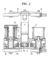
- Figure 2 is a partially sectional longitudunal view of an embodiment according to the invention.
- Figure 3 is a side view of the embodiment shown in Figure 2.
- Figure 4 is a partially sectional longitudinal view of another embodiment according to the invention.
- Fig. 1 the assembly is mounted around a pipe 1.
- a toothed belt 2 is routed over a first toothed belt pulley 3, then intimately over the periphery of the pipe 1 and finally over a second toothed belt pulley 3 with the smooth outer side of the belt 2 resting against the pipe 1.
- This section of the belt forms the inner leg 7 of the belt 2.
- the belt pulleys 3 are complemented with spring-loaded or lockable guide 4 rollers which compress the belt 2 against the belt pulley 3 so as to prevent slackening of the belt in its first leg 7. From the second belt pulley 3 the belt 2 returns to the first belt pulley 3 forming the freely hanging untensioned outer leg 8 which completes the folded loop of the belt 2.
- Fig. 1 shows the drive arrangement for the belt pulleys 3.
- the drive motor 5 is adapted between the belt pulleys 3 and the rotational drive of the motor 5 is geared to the belt pulleys 3 via intermediate gear wheels 6.
- Such an arrangement provides the belt pulleys 3 with synchronized rotational direction and speed. Consequently, the arrangement shown in the diagram is entirely symmetrical, and thus, in the above explanation, permits free interchanging of the functional descriptions of the elements symmetrically located around the center line.
- the belt 2 is first inserted over the first belt pulley 3 and locked with the help of the guide roller 4.
- the belt 2 is routed around the pipe 1 and then further inserted over the second belt pulley 3, simultaneously tensioning the inner leg 7 of formed loop tightly against the pipe 1.
- the belt 2 is locked onto the belt pulley 3 with the help of the guide roller 4, and the excess length of the belt 2 is allowed to sag as a slack loop.
- the belt pulleys 3 travel over the toothed belt 2, and the tension of the belt 2, together with the friction of the belt 2 against the pipe 1, keep the assembly stationary even when the guiding assembly is placed to the side of a pipe 1.
- the assembly is capable of travelling around the entire perimeter of the pipe 1, making it suitable for use on pipes aligned in any position.
- the belt 1 must be relatively wide to provide sufficient sideways guidance during the movement.
- Fig. 2 illustrates in greater detail an embodiment of the present invention.
- This embodiment of the assembly is constructed on a body comprised of two body parts 9.
- the drive motor 5 is mounted at the center line of the body 9.
- the belt pulleys 3 are mounted on shafts on the body 9, to both sides of the motor 5.
- the drive shaft of the motor 5 has a driving gear wheel 15, with intermediate gear wheels 6 placed to both sides of it.
- Mounted on the shaft of each belt pulley 3 is a driven gear wheel 16, both of which are in a meshing position with the intermediate gear wheel 6.
- the transmission chain formed in this manner provides synchronous drive for the belt pulleys 3.
- One of the belt pulleys 3 is directly driven via its shaft from the driven gear wheel 16. Between the second belt pulley 3 and its driven gear wheel 16 is adapted a spring-loaded ratchet 13 for belt tensioning during the installation of the belt.
- the ratchet 13 incorporates a coiled spring 14 whose one end is connected to the belt pulley 3 and the other end via the body of the ratchet 13 to the shaft of the driven gear wheel 16.
- the ratchet has a dual function in the assembly: firstly, it helps the mounting, and secondly, it assures steady tightness of the belt. After the belt is routed around the pipe during the mounting of the assembly, it is inserted over the belt pulley 3, 13 equipped with the ratchet and locked with the gear teeth.
- the belt is next tensioned properly by either pulling from the slack end of the belt, or alternatively, tightening the ratchet with a wrench, whereby the pawl mechanism of the ratchet 13 permits rotation of the belt pulley 3 and tensioning of the spring 14 of the ratchet 13.
- the mounting and tensioning of the belt is made extremely easy.
- the spring 14 of the ratchet 13 permits a small tolerance in the synchronized motion of the belt pulley 3. If the pipe outer surface has depressions, the spring 14 rotates the belt pulley 3 and thus tensions the belt.
- the spring provides for a small allowance in the inner leg length of the belt spanned between belt pulleys.
- the assembly shown in Fig. 2 travels on the pipe periphery supported by support wheels 10 and 11.
- the first support wheels 10 are mounted on the same shafts as the driven gear. wheels 16, making said support wheels 10 to rotate at the same speed as the belt pulleys 3.
- the second support wheels 11 are mounted to the ends of a lever 12 which is pivoted at its center to the end of the body of the drive motor 5.
- the center-pivoted lever 12 is mounted to the body of the motor 5 by a pivotal joint which permits the rotation of the lever 12 about its pivoted center point.
- Fig. 4 shows another embodiment of the invention.
- This assembly is constructed into a one-piece body 9.
- the body 9 is closed with the help of a cover plate 17.
- the placement of the elements and drive arrangements are similar to those of the above-described embodiment.
- the first support wheels 10 are mounted to the common shaft 18 of the driven gear wheels 16 and the belt pulleys 3.
- the shafts 18 of the belt pulleys extend through the belt pulleys 3 and reach approximately level with body end of the drive motor 5.
- the second support wheels 11 are free to rotate mounted in bearings at the ends of said shafts 18.
- This embodiment has no ratchet mechanism, but instead, one of the belt pulleys 3 is mounted on its shaft 18 via a spring 14.
- This spring 14 performs during use the same function as the ratchet mechanism spring, yet the tensioning of the belt 2 in this embodiment is slightly more difficult than in the embodiment equipped with the ratchet mechanism 13. Also the insertion of the belt 2 onto the belt pulleys 3 is slightly more difficult, since the second support wheels 11 cannot be turned aside. On the other hand, this assembly has a simpler mechanical construction than in the assembly of the embodiment described first.
- the drive motor of the assembly can be easily provided with a pulse sensor or equivalent position indicator, whereby the location of the assembly on the perimeter of the pipe can be readily determined.
- the drive transmission chain from the motor 5 to the belt pulleys can be implemented by means of a belt or chain, and the motor can be adapted to rotate only one of the belt pulleys. Then, the motor can be placed within the belt pulley, for instance.
- the spring-loaded or lockable guide rollers other means can be employed to secure the adherence of the belt to the perimeter of the belt pulley.
- the belt 2 resting against the pipe outer surface can be of different kinds.
- the essential requirement is that the belt is sufficiently wide and nonstretching in its longitudinal direction, and that it can be driven with the help of the belt pulleys without any essential slip.
- the belt outer surface resting against the pipe outer surface may be coated with a material exhibiting a high coefficient of friction.
- the belt length is advantageously dimensioned so that the slack leg does not become too long, while a free leg forming a longer loop as such has no detrimental effect on the function of the assembly.
- the belt can be replaced by a chain, for example, but then the sideways guidance of the assembly must be provided by a separate guiding assembly.
- the support wheels can be replaced by different types of rollers or even by glide surfaces.
- a caterpillar track can employed which is routed over the support wheels and for the length of its tensioned leg closely follows the pipe surface.
- the assembly is intended to carry an extremely heavy load, it can be designed for multiple transfer belts with respective belt pulleys to improve its load-carrying capacity.
- the sideways stability' is vastly enhanced by increasing the number-of belts to, e.g., two belts alone.
- the above-described embodiment can be designed to use two narrow belts.
- the assembly can be loaded with multiple different types of accessories.
- the most important herein is a transfer apparatus which can be used for transferring an ultrasonic transducer longitudinally, for example.
- Another interesting accessory could be a rechargeable battery system, whereby the cabling of the motor and the loading equipment cause no disturbance to the motion around the pipe.
- battery-powered operation is applicable to relatively lightweight assemblies only that can be operated from relatively small batteries. Owing to the large weight of high-capacity batteries, the use of rechargeable batteries is not possible in all locations.
Landscapes
- Physics & Mathematics (AREA)
- Health & Medical Sciences (AREA)
- Life Sciences & Earth Sciences (AREA)
- Chemical & Material Sciences (AREA)
- Analytical Chemistry (AREA)
- Biochemistry (AREA)
- General Health & Medical Sciences (AREA)
- General Physics & Mathematics (AREA)
- Immunology (AREA)
- Pathology (AREA)
- Optics & Photonics (AREA)
- Engineering & Computer Science (AREA)
- Mechanical Engineering (AREA)
- Investigating Or Analyzing Materials By The Use Of Ultrasonic Waves (AREA)
- Investigating Or Analyzing Materials By The Use Of Magnetic Means (AREA)
- Load-Engaging Elements For Cranes (AREA)
- Chain Conveyers (AREA)
- Vehicle Body Suspensions (AREA)
- Container Filling Or Packaging Operations (AREA)
- Turning (AREA)
- Measuring Pulse, Heart Rate, Blood Pressure Or Blood Flow (AREA)
- Mechanical Means For Catching Fish (AREA)
Applications Claiming Priority (2)
| Application Number | Priority Date | Filing Date | Title |
|---|---|---|---|
| FI922943 | 1992-06-24 | ||
| FI922943A FI93780C (fi) | 1992-06-24 | 1992-06-24 | Sovitelma erilaisten laitteiden kuljettamiseksi pitkänomaisten kappaleiden ympäri |
Publications (2)
| Publication Number | Publication Date |
|---|---|
| EP0578402A1 true EP0578402A1 (fr) | 1994-01-12 |
| EP0578402B1 EP0578402B1 (fr) | 1998-02-04 |
Family
ID=8535527
Family Applications (1)
| Application Number | Title | Priority Date | Filing Date |
|---|---|---|---|
| EP93304837A Expired - Lifetime EP0578402B1 (fr) | 1992-06-24 | 1993-06-21 | Ensemble pour le guidage de différents type d'équipement autours d'objets allongés |
Country Status (5)
| Country | Link |
|---|---|
| US (1) | US5385508A (fr) |
| EP (1) | EP0578402B1 (fr) |
| AT (1) | ATE163091T1 (fr) |
| DE (1) | DE69316799D1 (fr) |
| FI (1) | FI93780C (fr) |
Cited By (3)
| Publication number | Priority date | Publication date | Assignee | Title |
|---|---|---|---|---|
| US8146430B2 (en) | 2006-05-10 | 2012-04-03 | Jireh Industries Ltd. | Method and apparatus for conveying an ultrasonic sensor about an outer peripheral surface of a tube |
| CZ306666B6 (cs) * | 2015-12-29 | 2017-04-26 | Ĺ KODA JS a.s. | Manipulátor pro kontrolu potrubí, zejména pro kontrolu svarů potrubí s omezeným přístupem, a způsob uchycení manipulátoru k tomuto potrubí |
| CN107976313A (zh) * | 2017-11-29 | 2018-05-01 | 苏州金钜松机电有限公司 | 一种拉伸机的皮带测试组件 |
Families Citing this family (5)
| Publication number | Priority date | Publication date | Assignee | Title |
|---|---|---|---|---|
| US8668422B2 (en) * | 2004-08-17 | 2014-03-11 | Mattson Technology, Inc. | Low cost high throughput processing platform |
| FR2994401B1 (fr) * | 2012-08-10 | 2014-08-08 | Commissariat Energie Atomique | Procede et systeme d'assistance au pilotage d'un robot a fonction de detection d'intention d'un operateur |
| US9528584B2 (en) * | 2015-05-14 | 2016-12-27 | Gates Corporation | Belt drive mechanism |
| DE102016113803A1 (de) * | 2015-07-28 | 2017-02-02 | Steering Solutions Ip Holding Corporation | Riemenscheibenbaugruppe mit leerlaufrolle, kraftunterstützungssystem mit riemenscheibenbaugruppe und verfahren |
| FR3166210A1 (fr) * | 2024-09-10 | 2026-03-13 | Intercontrole | Ensemble de contrôle d’une tuyauterie |
Citations (4)
| Publication number | Priority date | Publication date | Assignee | Title |
|---|---|---|---|---|
| US3918697A (en) * | 1974-07-15 | 1975-11-11 | Kenneth H Gregory | Machine for rotatable supporting a tank during the manufacture thereof |
| GB2012047A (en) * | 1978-01-05 | 1979-07-18 | Boc Subocean Services Ltd | Non-destructive testing of welds |
| GB2032046A (en) * | 1978-09-26 | 1980-04-30 | Sgs Sonomatic Ltd | Circumnavigating continuous surfaces |
| US4540872A (en) * | 1984-02-06 | 1985-09-10 | Dayton Machine Tool Company | Apparatus for rotating a generally cylindrical heavy workpiece for treatment |
Family Cites Families (3)
| Publication number | Priority date | Publication date | Assignee | Title |
|---|---|---|---|---|
| US1320044A (en) * | 1919-10-28 | Belt-tightener | ||
| US1869692A (en) * | 1931-05-01 | 1932-08-02 | Whitin Machine Works | Spindle drive for spinning or twisting machines |
| US2090423A (en) * | 1935-11-05 | 1937-08-17 | John A Morrell | Reverse belt and pulley drive |
-
1992
- 1992-06-24 FI FI922943A patent/FI93780C/fi active
-
1993
- 1993-06-21 AT AT93304837T patent/ATE163091T1/de not_active IP Right Cessation
- 1993-06-21 DE DE69316799T patent/DE69316799D1/de not_active Expired - Lifetime
- 1993-06-21 EP EP93304837A patent/EP0578402B1/fr not_active Expired - Lifetime
- 1993-06-23 US US08/080,127 patent/US5385508A/en not_active Expired - Fee Related
Patent Citations (4)
| Publication number | Priority date | Publication date | Assignee | Title |
|---|---|---|---|---|
| US3918697A (en) * | 1974-07-15 | 1975-11-11 | Kenneth H Gregory | Machine for rotatable supporting a tank during the manufacture thereof |
| GB2012047A (en) * | 1978-01-05 | 1979-07-18 | Boc Subocean Services Ltd | Non-destructive testing of welds |
| GB2032046A (en) * | 1978-09-26 | 1980-04-30 | Sgs Sonomatic Ltd | Circumnavigating continuous surfaces |
| US4540872A (en) * | 1984-02-06 | 1985-09-10 | Dayton Machine Tool Company | Apparatus for rotating a generally cylindrical heavy workpiece for treatment |
Cited By (4)
| Publication number | Priority date | Publication date | Assignee | Title |
|---|---|---|---|---|
| US8146430B2 (en) | 2006-05-10 | 2012-04-03 | Jireh Industries Ltd. | Method and apparatus for conveying an ultrasonic sensor about an outer peripheral surface of a tube |
| CZ306666B6 (cs) * | 2015-12-29 | 2017-04-26 | Ĺ KODA JS a.s. | Manipulátor pro kontrolu potrubí, zejména pro kontrolu svarů potrubí s omezeným přístupem, a způsob uchycení manipulátoru k tomuto potrubí |
| EP3187871A1 (fr) | 2015-12-29 | 2017-07-05 | Skoda JS a.s. | Manipulateur d'examen de pipeline, de préférence pour l'examen de soudures de pipelines dans des lieux difficiles d'accès et procédé de fixation d'un tel manipulateur au pipeline |
| CN107976313A (zh) * | 2017-11-29 | 2018-05-01 | 苏州金钜松机电有限公司 | 一种拉伸机的皮带测试组件 |
Also Published As
| Publication number | Publication date |
|---|---|
| DE69316799D1 (de) | 1998-03-12 |
| US5385508A (en) | 1995-01-31 |
| FI922943A0 (fi) | 1992-06-24 |
| ATE163091T1 (de) | 1998-02-15 |
| FI93780B (fi) | 1995-02-15 |
| FI93780C (fi) | 1995-05-26 |
| EP0578402B1 (fr) | 1998-02-04 |
| FI922943L (fi) | 1993-12-25 |
Similar Documents
| Publication | Publication Date | Title |
|---|---|---|
| EP0578402B1 (fr) | Ensemble pour le guidage de différents type d'équipement autours d'objets allongés | |
| US5333809A (en) | Reel support with horizontal and vertical adjustment | |
| KR101363511B1 (ko) | 배관 용접부의 그라인딩 장치 | |
| CA2356822C (fr) | Chariot de soudage | |
| JPH05196107A (ja) | 直動コンベアユニット | |
| CA2103390C (fr) | Convoyeur pour produits de forme tres allongee | |
| JP2006170685A (ja) | 管状構造物用の自動超音波探傷装置 | |
| JPS5828029B2 (ja) | パイプ突合せ溶接用溶接装置 | |
| KR101815870B1 (ko) | 케이블 로봇용 윈치모듈 | |
| US7175162B1 (en) | Screw driven hoist | |
| EP3187871A1 (fr) | Manipulateur d'examen de pipeline, de préférence pour l'examen de soudures de pipelines dans des lieux difficiles d'accès et procédé de fixation d'un tel manipulateur au pipeline | |
| US5017083A (en) | Apparatus for loading and/or unloading industrial presses | |
| EP0249782B1 (fr) | Appareil d'entraînement de tubes utilisant des courroies de transmission flexible | |
| US4387598A (en) | Pipe scanner mechanism | |
| KR101616370B1 (ko) | 파이프 개선 장치 및 파이프 개선 방법 | |
| JPH03221312A (ja) | 管回転装置 | |
| US4905516A (en) | Wall thickness measuring device for pipes, cable casings and the like, more particularly of extruded plastics | |
| GB2032046A (en) | Circumnavigating continuous surfaces | |
| JPH09285893A (ja) | 自動溶接装置 | |
| US5261860A (en) | Drive apparatus | |
| US4826116A (en) | Tipping device for a movie-camera-supporting cradle | |
| US4555853A (en) | Drive for position controlled linearly movable carriage | |
| JP4425462B2 (ja) | トランスミッション装置 | |
| PL296004A1 (fr) | ||
| JPH01219506A (ja) | 設備配管の肉厚測定装置 |
Legal Events
| Date | Code | Title | Description |
|---|---|---|---|
| PUAI | Public reference made under article 153(3) epc to a published international application that has entered the european phase |
Free format text: ORIGINAL CODE: 0009012 |
|
| AK | Designated contracting states |
Kind code of ref document: A1 Designated state(s): AT BE CH DE DK ES FR GB IE IT LI NL PT SE |
|
| 17P | Request for examination filed |
Effective date: 19940512 |
|
| 17Q | First examination report despatched |
Effective date: 19970207 |
|
| GRAG | Despatch of communication of intention to grant |
Free format text: ORIGINAL CODE: EPIDOS AGRA |
|
| GRAG | Despatch of communication of intention to grant |
Free format text: ORIGINAL CODE: EPIDOS AGRA |
|
| GRAH | Despatch of communication of intention to grant a patent |
Free format text: ORIGINAL CODE: EPIDOS IGRA |
|
| GRAH | Despatch of communication of intention to grant a patent |
Free format text: ORIGINAL CODE: EPIDOS IGRA |
|
| GRAA | (expected) grant |
Free format text: ORIGINAL CODE: 0009210 |
|
| AK | Designated contracting states |
Kind code of ref document: B1 Designated state(s): AT BE CH DE DK ES FR GB IE IT LI NL PT SE |
|
| PG25 | Lapsed in a contracting state [announced via postgrant information from national office to epo] |
Ref country code: NL Free format text: LAPSE BECAUSE OF FAILURE TO SUBMIT A TRANSLATION OF THE DESCRIPTION OR TO PAY THE FEE WITHIN THE PRESCRIBED TIME-LIMIT Effective date: 19980204 Ref country code: LI Free format text: LAPSE BECAUSE OF FAILURE TO SUBMIT A TRANSLATION OF THE DESCRIPTION OR TO PAY THE FEE WITHIN THE PRESCRIBED TIME-LIMIT Effective date: 19980204 Ref country code: IT Free format text: LAPSE BECAUSE OF FAILURE TO SUBMIT A TRANSLATION OF THE DESCRIPTION OR TO PAY THE FEE WITHIN THE PRESCRIBED TIME-LIMIT;WARNING: LAPSES OF ITALIAN PATENTS WITH EFFECTIVE DATE BEFORE 2007 MAY HAVE OCCURRED AT ANY TIME BEFORE 2007. THE CORRECT EFFECTIVE DATE MAY BE DIFFERENT FROM THE ONE RECORDED. Effective date: 19980204 Ref country code: FR Free format text: LAPSE BECAUSE OF FAILURE TO SUBMIT A TRANSLATION OF THE DESCRIPTION OR TO PAY THE FEE WITHIN THE PRESCRIBED TIME-LIMIT Effective date: 19980204 Ref country code: ES Free format text: THE PATENT HAS BEEN ANNULLED BY A DECISION OF A NATIONAL AUTHORITY Effective date: 19980204 Ref country code: CH Free format text: LAPSE BECAUSE OF FAILURE TO SUBMIT A TRANSLATION OF THE DESCRIPTION OR TO PAY THE FEE WITHIN THE PRESCRIBED TIME-LIMIT Effective date: 19980204 Ref country code: BE Free format text: LAPSE BECAUSE OF FAILURE TO SUBMIT A TRANSLATION OF THE DESCRIPTION OR TO PAY THE FEE WITHIN THE PRESCRIBED TIME-LIMIT Effective date: 19980204 Ref country code: AT Free format text: LAPSE BECAUSE OF FAILURE TO SUBMIT A TRANSLATION OF THE DESCRIPTION OR TO PAY THE FEE WITHIN THE PRESCRIBED TIME-LIMIT Effective date: 19980204 |
|
| REF | Corresponds to: |
Ref document number: 163091 Country of ref document: AT Date of ref document: 19980215 Kind code of ref document: T |
|
| REG | Reference to a national code |
Ref country code: CH Ref legal event code: EP |
|
| REF | Corresponds to: |
Ref document number: 69316799 Country of ref document: DE Date of ref document: 19980312 |
|
| PG25 | Lapsed in a contracting state [announced via postgrant information from national office to epo] |
Ref country code: SE Free format text: LAPSE BECAUSE OF FAILURE TO SUBMIT A TRANSLATION OF THE DESCRIPTION OR TO PAY THE FEE WITHIN THE PRESCRIBED TIME-LIMIT Effective date: 19980504 Ref country code: PT Free format text: LAPSE BECAUSE OF FAILURE TO SUBMIT A TRANSLATION OF THE DESCRIPTION OR TO PAY THE FEE WITHIN THE PRESCRIBED TIME-LIMIT Effective date: 19980504 Ref country code: DK Free format text: LAPSE BECAUSE OF FAILURE TO SUBMIT A TRANSLATION OF THE DESCRIPTION OR TO PAY THE FEE WITHIN THE PRESCRIBED TIME-LIMIT Effective date: 19980504 |
|
| PG25 | Lapsed in a contracting state [announced via postgrant information from national office to epo] |
Ref country code: DE Free format text: LAPSE BECAUSE OF FAILURE TO SUBMIT A TRANSLATION OF THE DESCRIPTION OR TO PAY THE FEE WITHIN THE PRESCRIBED TIME-LIMIT Effective date: 19980505 |
|
| PG25 | Lapsed in a contracting state [announced via postgrant information from national office to epo] |
Ref country code: IE Free format text: LAPSE BECAUSE OF NON-PAYMENT OF DUE FEES Effective date: 19980621 Ref country code: GB Free format text: LAPSE BECAUSE OF NON-PAYMENT OF DUE FEES Effective date: 19980621 |
|
| NLV1 | Nl: lapsed or annulled due to failure to fulfill the requirements of art. 29p and 29m of the patents act | ||
| REG | Reference to a national code |
Ref country code: IE Ref legal event code: FG4D Free format text: 78733 |
|
| EN | Fr: translation not filed | ||
| REG | Reference to a national code |
Ref country code: CH Ref legal event code: PL |
|
| PLBE | No opposition filed within time limit |
Free format text: ORIGINAL CODE: 0009261 |
|
| STAA | Information on the status of an ep patent application or granted ep patent |
Free format text: STATUS: NO OPPOSITION FILED WITHIN TIME LIMIT |
|
| 26N | No opposition filed | ||
| GBPC | Gb: european patent ceased through non-payment of renewal fee |
Effective date: 19980621 |