EP0579051A2 - System zur aseptischen Entleerung von flexiblen Nahrungsmittelbehältern - Google Patents
System zur aseptischen Entleerung von flexiblen Nahrungsmittelbehältern Download PDFInfo
- Publication number
- EP0579051A2 EP0579051A2 EP93110526A EP93110526A EP0579051A2 EP 0579051 A2 EP0579051 A2 EP 0579051A2 EP 93110526 A EP93110526 A EP 93110526A EP 93110526 A EP93110526 A EP 93110526A EP 0579051 A2 EP0579051 A2 EP 0579051A2
- Authority
- EP
- European Patent Office
- Prior art keywords
- container
- bag
- mouthpiece
- emptying
- fact
- Prior art date
- Legal status (The legal status is an assumption and is not a legal conclusion. Google has not performed a legal analysis and makes no representation as to the accuracy of the status listed.)
- Withdrawn
Links
Images



Classifications
-
- A—HUMAN NECESSITIES
- A23—FOODS OR FOODSTUFFS; TREATMENT THEREOF, NOT COVERED BY OTHER CLASSES
- A23G—COCOA; COCOA PRODUCTS, e.g. CHOCOLATE; SUBSTITUTES FOR COCOA OR COCOA PRODUCTS; CONFECTIONERY; CHEWING GUM; ICE-CREAM; PREPARATION THEREOF
- A23G9/00—Frozen sweets, e.g. ice confectionery, ice-cream; Mixtures therefor
- A23G9/04—Production of frozen sweets, e.g. ice-cream
- A23G9/22—Details, component parts or accessories of apparatus insofar as not peculiar to a single one of the preceding groups
- A23G9/28—Details, component parts or accessories of apparatus insofar as not peculiar to a single one of the preceding groups for portioning or dispensing
-
- A—HUMAN NECESSITIES
- A23—FOODS OR FOODSTUFFS; TREATMENT THEREOF, NOT COVERED BY OTHER CLASSES
- A23G—COCOA; COCOA PRODUCTS, e.g. CHOCOLATE; SUBSTITUTES FOR COCOA OR COCOA PRODUCTS; CONFECTIONERY; CHEWING GUM; ICE-CREAM; PREPARATION THEREOF
- A23G7/00—Other apparatus or process specially adapted for the chocolate or confectionery industry
-
- B—PERFORMING OPERATIONS; TRANSPORTING
- B65—CONVEYING; PACKING; STORING; HANDLING THIN OR FILAMENTARY MATERIAL
- B65B—MACHINES, APPARATUS OR DEVICES FOR, OR METHODS OF, PACKAGING ARTICLES OR MATERIALS; UNPACKING
- B65B69/00—Unpacking of articles or materials, not otherwise provided for
- B65B69/005—Unpacking of articles or materials, not otherwise provided for by expelling contents, e.g. by squeezing the container
Definitions
- the invention relates to a system for aseptically emptying flexible containers for sterile foodstuff products, in which a flexible container is in the form of a bag formed by laminated plastic sheet material is provided with a suitable emptying mouthpiece that can prevent any contact with the air and with the external surroundings during emptying of the bag.
- a number of the products currently treated with aseptic methods are semi-finished, such as ingredients that are subsequently used to obtain various finished products, or are stored at the time the raw materials are processed in order to be then packaged in containers which will be used over a period of a year.
- the containers used for the semi-finished products are generally large. In the case, for example, of stainless steel tanks, the dimensions are in multiples of ten cubic metres, or in hundreds of litres for dense or non-homogeneous products for which smaller-sized, containers are preferred in order to avoid the risk of excessive waste during emptying or the stratification of the product during the storage period.
- the main object of this invention is to provide a system for emptying flexible, disposable containers that enables the retrieval from them of sterile products, at ambient temperature, to be fed to a processing plant, without the product coming into contact with the environment or with non-sterile parts that could re-contaminate.
- a further object of this invention is to provide a system for aseptically emptying flexible containers for foodstuff products such as to avoid damage to the product, in particular to products that are non-homogeneous or with solid parts immersed in a conserving liquid.
- Another object of this invention is to provide an emptying system that can guarantee the integrity of the container during emptying, so as to avoid the high risk of re-contamination of the product and of the packaging plant located downstream of the emptying section.
- An additional object of this invention is to provide a method for aseptically emptying flexible containers, as described above, which has high efficiency, such as to enable maximum retrieval of the product up to a high percentage value of, or close to, 98%.
- Most containers for semi-finished products on the market are in the form of flexible plastic bags with aluminium protection to heighten the barrier effect against oxygen in the air.
- the bags are placed in a further, rigid supporting container which allows them to be stacked and which, according to its shape, may be made up of a cylindrical or conic metal drum or by a wooden crate of parallelepiped shape with capacity varying between 200 and 1,000 litres.
- the bags are normally provided with a filling mouthpiece sealed with a snap-on cap and are emptied simply by breaking the bag.
- said filling mouthpiece may be also used for aseptic emptying the bag or, where necessary, the bag may be provided with an additional, emptying mouthpiece.
- a first system according to the invention will now be described that provides for the use of an auxiliary drum equipped for the emptying of a flexible container after the usual supporting rigid container has been removed.
- reference number 10 indicates a flexible plastic container, hereinafter designated more simply as "bag”, for containing a food substance previously aseptically packaged in said bag.
- the bag 10 is provided with an emptying mouthpiece 11 and is housed in a rigid supporting container 12 in the shape of a truncated cone, normally closed with its own cover, which must be removed beforehand.
- reference number 14 indicates an auxiliary container or "auxiliary drum” which must be let down over the rigid container 12 until it totally envelopes it in order to subsequently enable emptying of the bag through the emptying mouthpiece 11; without need of cutting the bag and therefore in conditions that are entirely sterile, as explained below.
- auxiliary drum 14 is initially fully raised there being a space from the roller set 13 in order the rigid container 12 holding the bag 10 may be positioned on said roller set.
- reference number 15 in figure 1 indicates a gripping means for holding up the auxiliary drum 14, for example by the bottom 14A which is suitably arranged to allow the mouthpiece 11 to emerge from an opening 16 provided with means 17 for clamping the mouthpiece protruding from the bottom 14A of the auxiliary drum, as diagrammatically shown in figures 2A and 2B of the drawings.
- the auxiliary drum 14 of the example in Figures 1 to 6 is a container of a suitable shape and size for enclosing a normal rigid supporting container 12 for the bag 10. For this reason the auxiliary drum 14 is open on the side opposed to its bottom 14A. Since the auxiliary drum 14 is to be completely superimposed on the rigid container 12 so as to house it internally, the internal diameter or dimensions of the auxiliary drum 14 shall be slightly greater than the maximum diameter or maximum external dimensions of the container 12.
- auxiliary drum 14 is totally raised with its open side facing downwards, while the rigid container 12 is positioned on the roller set 13 with its open side, facing upwards to access the bag 10.
- the auxiliary drum 14, held by its bottom 14A by the gripping device 15, is lowered and made to completely slip over the rigid container 12 as shown in Figure 2A.
- the following stage comprises an upsetting that is a rotation through 180 degrees, of the auxiliary drum 14 with the rigid container 12 and the flexible bag 10 inside it, in such a way that the emptying mouthpiece 11 faces now downwards.
- the assembly consisting of the auxiliary drum 14, the container 12, and the flexible bag 10 is transferred by a roller set 18, to an upsetting area shown in Figures 3 and 4 in the appended drawings.
- This area is provided with a revolving device having roller sets 18 and 19, able to upset the entire assembly by turning it upside down through 180 degrees, as is shown by a comparison between Figures 3 and 4 of the appended drawings. From Fig, 4 it will in fact be seen that the position of the roller sets 18 and 19 is reversed, that the auxiliary drum 14 now has its mouthpiece engaged in the downward facing bottom of the auxiliary drum, while the open side 14B of the auxiliary drum is now facing upwards. After the reversion shown in Fig. 4, the entire auxiliary drum 14 is transferred to a position, shown in Fig. 5, for removing the rigid container 12.
- auxiliary drum 14 rests on another roller set 20 while a suitable gripping device 21 is lowered to grip the rigid container 12 by its bottom, to raise and withdraw it from the auxiliary drum 14, so that the bag 10 gently slips out of the container 12 and, in this way, remains entirely inside the auxiliary drum 14.
- the device for removing the container 12 may be of any shape or type: for example, it may consist in a grasping device that take hold at the bottom the container 12 in a suitable position, or any other mechanical and/or magnetic device that firmly attaches to the bottom or to the sides of the rigid container and which grips it with sufficient force to make its withdrawal feasible.
- the open side of the auxiliary drum 14, in this example, is so designed to be gripped by a cover 23 provided with a pressure device for thrusting or compressing the flexible bag 10, as explained below, and which in the example in Fig. 6 is represented in the form of a piston member 24 slidably supported by the cover 23 and operated by a hydraulic or pneumatic cylinder 25, or by any other linear actuator, to be moved within the auxiliary drum 14 to and from the bottom 14A.
- the pressure device for emptying the bag 10, here represented in the form of a piston member 24, can in fact be implemented in any appropriate way and, as an alternative to what is shown, according to the nature of the product to be discharged, and the operating conditions, the mechanical thrusting piston may be replaced by any other thrusting device, including pneumatic, as illustrated below.
- a suitable device To aseptically empty the bag 10 in the position in Fig. 6 a suitable device must be provided that enables aseptic connection of the bag mouthpiece 11 to a discharge duct 25.
- the duct 25 is connected by a valve 26 to a movable or flexible duct 27 provided with suitable sealing means to enable a sealed connection with the mouthpiece 11.
- the duct 27, through valves 28 and 29, is connected to a feed circuit for disinfecting fluid to clean those parts of the mouthpiece 11 and of the tube 27 which come into contact with the atmosphere or which may contain product residue that has come into contact with the air between emptying one bag and emptying the next one and, therefore, has lost its aseptic characteristics.
- reference number 30 in Fig. 6 indicates a piercing device for perforating the mouthpiece 11 by penetrating into the mouthpiece under aseptic conditions through the mobile tube 27 as described below with reference to an embodiment shown in Fig. 9.
- valves 26, 28 and 29 are initially shut out. Only after tube 27 has been coupled to the mouthpiece 11, so as to form a sealed connection, valves 28 and 29 are opened to allow circulation of a cleaning fluid, for example steam and/or sterilising chemical agents such as iodophors, oxygenated water, chlorine and others. Following this, valves 28 and 29 are again shut out and device 30 is operated to perforate the mouthpiece 11.
- the discharge valve 26 is opened and, simultaneously, the pressure device 24 is operated to press against the bag 10 without breaking it, the latter remaining supported by the counter-thrust provided by the sides of the auxiliary drum 14, to expel the foodstuff product in the direction of the mouthpiece 11 and into the discharge duct 25.
- valve 26 When emptying of the bag 10 has been completed the valve 26 is shut out, the pressure device 24 is moved backwards, the cover 23 is released from the auxiliary drum, and the latter is returned to the position in Fig. 1 to the cycle with a new container 12 which, in the meantime, has been positioned and prepared on the roller set 13.
- the bag in substitution of the pierceable special emptying mouthpiece 11, the bag may be emptied from the normal filling mouthpiece which can be made perforable at the moment the connection is made with the discharging duct 25, after removed of the closing plug.
- the mouthpiece may be perforated with any mechanical system, or with pressurised gas or any other device that can guarantee aseptic conditions for the entire process to keep the food product sterile inside the bag to be emptied and in the direction of the discharge pipe connected to a processing plant.
- the apparatus mainly comprises a frame 31 provided with four roller sets 13, 18, 19, and 20 which, together, define a rolling surface for the rigid container 12 and the auxiliary drum 14.
- the frame 31 has at its top a rail 32 along which slides a hoisting device 33 provided with a magnetic or mechanical gripping member 34 which, before the reversing operation, takes hold of an auxiliary drum 14 that has to be raised and slipped over a rigid container 12 underneath and, after the reversing, takes hold of the rigid container 12 to draw it off the auxiliary drum as previously described in Figures 1 to 5 of the appended drawings.
- the first roller set 13 is provided with idling rollers on which the container 12, with the bag 10 containing the food product in perfectly aseptic conditions, is placed.
- the second roller set 18 is provided with motor-driven rollers to enable the containers to be displaced and the third roller set 19 is again with idling rollers.
- Roller sets 18 and 19 form part of a device for reversing the drums and are positioned at the opposite ends of a revolving open-side cage 35.
- the cage 35 with the containers inside it, can be driven to rotate through 180 degrees about a central motor-driven shaft 36, suitable clamping devices 37 being provided to prevent the containers from moving and from falling down during the reversing movement.
- the fourth roller set 20, shown both in Fig. 7 and in Fig. 8, is in its turn has motor-driven rollers for transferring the containers from the central position to a final position where the bag 10 is aseptically connected to the perforation device 30 for emptying the bag.
- the apparatus in Figures 7 and 8 also comprises a cover moving device 38 for putting on and taking off the cover 23 with the pressure device 24 for emptying the flexible bag.
- the device 38 in the example shown, is laterally connected by a hinge at 39 to an upright 31 and is driven by a hydraulic or other type of actuator, not shown, to rotate between a position in alignment with the auxiliary drum 14 below and a lateral position to allow the rigid container to be drawn off as described with reference to Fig. 5.
- the specially equipped cover 23 is supported by the device 38, for example by crossed rods, so as to be moved between a raised position in Fig. 7, with the pressure member 24 completely withdrawn from the auxiliary drum 14, and a lowered position as shown by the broken lines in Fig. 8, in which the pressure device 24 is inside the auxiliary drum 14 and in which the cover 23 firmly grips the open edge of the auxiliary drum by means of gripping devices 40 operated by respective drive cylinders 41.
- the device 30 comprises a supporting structure made up of a hollow cylindrical body 42 that can be connected by a hinge to the structure 31 of the apparatus.
- the cylindrical body 42 is closed at its ends by a lower head piece 43 and by an upper head piece 44.
- a first tubular element 45 is fixed to and extends upwards from the upper head piece 44 to connect with the lower head piece 46 of a second hollow cylindrical body 47 provided with a sliding sleeve 48 defining a chamber 49 for the sterile connection to the discharge duct through a lateral pipe fitting 50.
- the sleeve 48 At its upper end the sleeve 48 has an internal flange defining a seal about a central hole 51 for the connection with the emptying mouthpiece 11 of the flexible container 10 and for passing through of a piercing member for perforating the bag as described below.
- the movable sleeve 48 is made to slide between a backward position in which it is disengaged from the mouthpiece 11, and a forward position in which it forms a seal against the mouthpiece 11.
- This movement is controlled by a fork member 52 which has its pivotal axis on an arm 53 protruding from the tubular element 45, said fork member 52 being driven by a hydraulic or pneumatic cylinder 54. It is clear that the sliding movement of the sleeve for aseptic connection 48 can be obtained in any other suitable form.
- the piercing device can be of any type: mechanical, of pressure type and/or gas jet actuated.
- the device for perforating the bag or a closing membrane with which the mouthpiece 11 may be fitted comprises a lance 55 mounted on the upper end of a rod 55' slidingly positioned in an internal tubular element 57 extending from the cylindrical body 42 along the tubular element 45, inside the chamber 49 and towards the sliding sleeve 48.
- the internal tubular element 57 is closed at its lower end by a plug 57' defining the seat for a biasing spring 58 for the perforating lance 55; the lance in the lowered position shown in Fig. 9 sealingly closes the upper extremity of the tubular element 57.
- the tubular element 57 through a conduit 56 in the flange 44, can also be connected to a duct for the circulation of a cleaning fluid for cleaning and disinfecting the chamber 49 and the mouthpiece 11, as previously described in relation to Fig. 6.
- the pressure of the cleaning fluid fed through the tubular element 57 slightly raises the lance 55 to allow the cleaning fluid to circulate.
- the lance 55 can be raised to the position for perforating the bag, shown by the broken line in Fig. 9, by causing the internal tube 57 to slide upwards, guided by the external tubular element 45, by means of the hydraulic or pneumatic cylinder 59.
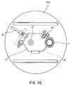
- Fig. 10 in the appended drawings is an enlarged view of Fig. 28 and shows a specific solution for the bottom wall 14A of the auxiliary drum and for the means for clamping the emptying mouthpiece 11.
- Reference number 16 in fig. 10 indicates the opening in the bottom 14A through which the mouthpiece 11 is withdrawn and which is normally closed by lid 17 hingedly connected at 60 by a double hinge having orthogonal axes.
- the lid 17, at its lateral edge, is shaped to clamp the mouthpiece 11 in the narrow part of the opening 16 and is, in its turn, clamped in the closing position by a rotating lever 61 mounted on the bottom 14A of the auxiliary drum.
- a knob 17' facilitates taking hold of the lid in order to raise it. It is obvious, however, that solutions other than that described are possible.
- the following figures 11 and 12 show two variants relating to different configurations of the pressure member 24 for compressing the bag inside the auxiliary drum 14 or the container 12, one lateral side of which is diagrammatically shown in Figures 11 and 12 by a broken line.
- the pressure member 24 partially shown in the first solution in Fig. 11 comprises a shaped plate 62 connected to the piston rod of a drive cylinder indicated by reference number 25 in the preceding figures.
- the plate 62 together with a circular-shaped counter plate 63 defines an annular seat 64 which holds an inflatable tubular member 65 forming a pneumatic seal that, during the compression of the flexible bag, prevents the latter from creeping up and being squeezed between the outside edge of the pressure member 24 and the inner face of the wall of the auxiliary drum 14.
- the plate 62 through rods 66 supports a small thrust plate 67 that comes into contact with the bag to be emptied.
- the thrust plate 67 can be rigidly or movably connected to the plate 62 such as to allow a slight backward displacement with respect to plate 62. This slight displacement of the thrust plate 67 can serve to radially thrust a possible further seal (not shown) that can be elastically deformed, provided for example between the pneumatic seal 65 and the outside edge of the thrust plate 67.
- a similar solution is shown for example in the following Fig.
- the shaped plate 62 has a circular fin 68 facing downwards and slanted inwards so as to define a truncated-cone thrust surface able to make an elastic seal 69 expand radially outwards until it is brought into contact with the internal wall of the auxiliary drum 14 by means of a slight backwards movement of the thrust plate 67 with respect to the shaped plated 62 as a result of the reaction that the thrust plate undergoes at the moment of the initial thrusting on the bag.
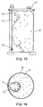
- these means comprise a long nozzle 71, that connects with a compressed air or gas source and extends through the cover 70 inside the container 12 and, effectively, down the latter's entire length.
- the nozzle 71 is provided at one or more points with openings 72 for the escape of the compressed air which, in this way, tends to compress the flexible bag 10 against an opposing wall of the container 12 and therefore to squeeze the product out for example, through the filling mouthpiece 11' after the latter has been suitably connected to a discharge duct in an aseptic manner, for example by means of a valve device of the kind previously described.
- Fig. 14 differs from that in Fig. 13 solely in the fact that here use is made of an inflatable thrust element 73 again mounted on the cover 70, which gradually expands inside the container 12 and increasingly presses against the flexible bag 10 until it completely empties the latter.
- This solution has the advantage of introducing a safety element that prevents a direct contact between gas or air released by the nozzle 71 and the flexible bag 10 to be emptied.
- the shape and the position of the nozzles 71 and of one or more inflatable elements for compressing the bag can vary with respect to what has been shown, without thereby departing from the innovative principle of this invention which, on the basis of the aseptic emptying methods explained, consists essentially in providing the flexible bag with a discharge mouthpiece which may be the bag filling mouthpiece or an additional mouthpiece; in providing said mouthpiece with pierceable part that can be perforated; by placing over the open side of a rigid supporting container which may be equally the rigid container normally used for storage or a separate auxiliary container, a closing cover provided with pressure means for thrusting and compressing the bag; the emptying mouthpiece of the flexible container is therefore made to protrude out from one side of the rigid supporting container, which may be the side of the specially equipped cover or the bottom of the container or auxiliary container.
- the mouthpiece or the area of the bag at the mouthpiece is perforated in such a way as to aseptically connect the mouthpiece to a discharge duct, and the aseptic emptying of the flexible bag is effected by compressing it from inside the rigid supporting container in the direction of the emptying mouthpiece, while the flexible bag is supported by the rigid container that totally surrounds it and which prevents its rupture.
Landscapes
- Engineering & Computer Science (AREA)
- Life Sciences & Earth Sciences (AREA)
- Chemical & Material Sciences (AREA)
- Food Science & Technology (AREA)
- Polymers & Plastics (AREA)
- Mechanical Engineering (AREA)
- Control And Other Processes For Unpacking Of Materials (AREA)
- Basic Packing Technique (AREA)
Applications Claiming Priority (2)
| Application Number | Priority Date | Filing Date | Title |
|---|---|---|---|
| ITMI921717A IT1255344B (it) | 1992-07-15 | 1992-07-15 | Sistema per lo svuotamento asettico di contenitori flessibili per prodotti alimentari |
| ITMI921717 | 1992-07-15 |
Publications (2)
| Publication Number | Publication Date |
|---|---|
| EP0579051A2 true EP0579051A2 (de) | 1994-01-19 |
| EP0579051A3 EP0579051A3 (en) | 1994-05-11 |
Family
ID=11363675
Family Applications (1)
| Application Number | Title | Priority Date | Filing Date |
|---|---|---|---|
| EP19930110526 Withdrawn EP0579051A3 (en) | 1992-07-15 | 1993-07-01 | System for aseptically emptying flexible foodstuff containers |
Country Status (2)
| Country | Link |
|---|---|
| EP (1) | EP0579051A3 (de) |
| IT (1) | IT1255344B (de) |
Cited By (15)
| Publication number | Priority date | Publication date | Assignee | Title |
|---|---|---|---|---|
| WO1997032807A3 (en) * | 1996-03-04 | 1997-10-16 | Loctite Ireland Ltd | Fluid flow connector, fluid pressure mechanism and product tank lid for fluids such as adhesives |
| GB2367105A (en) * | 2000-09-26 | 2002-03-27 | Nicolas Anastasiou | Cleaning conduits, especially in milk vending machines |
| WO2004058020A1 (en) * | 2002-12-24 | 2004-07-15 | Nestec S.A. | Clean-in-place automated food or beverage dispenser |
| GB2398772A (en) * | 2003-01-27 | 2004-09-01 | D C Norris & Co | Apparatus for evacuating bags |
| USD555967S1 (en) | 2005-08-12 | 2007-11-27 | Carlsberg Breweries A/S | Draught system |
| WO2008098385A1 (de) * | 2007-02-14 | 2008-08-21 | Medela Holding Ag | Entsorgungsvorrichtung für körperflüssigkeits-sammelbeutel und verfahren |
| US7562793B2 (en) | 2005-02-08 | 2009-07-21 | Nestec S.A. | Dispensing device with self-cleaning nozzle |
| EP2308760A1 (de) * | 2009-10-07 | 2011-04-13 | Immobiliare Felloni di Felloni Massimo | Entsorgungsanlage, insbesondere für leicht verformbare Behälter |
| US8028857B2 (en) | 2003-05-06 | 2011-10-04 | Carlsberg Breweries A/S | Method for dispensing a beverage and devices therefor |
| US8181825B2 (en) | 2005-02-08 | 2012-05-22 | Nestec S.A. | Hygienic beverage mixing and whipping assembly |
| EP2491792A1 (de) * | 2011-02-28 | 2012-08-29 | ALI S.p.A. - Carpigiani Group | Maschine zur Herstellung und Abgabe von flüssigen, halbflüssigen und/oder halbfesten Lebensmittelprodukten |
| EP2612826A1 (de) * | 2012-01-04 | 2013-07-10 | RUDOLF WILD GmbH & CO. KG | Folienbeutel |
| ITMI20122219A1 (it) * | 2012-12-21 | 2014-06-22 | Gaetano Molinari | Sistema di travaso di gel in ambito medicale o paramedicale |
| CN111776377A (zh) * | 2019-12-16 | 2020-10-16 | 浙江厚达智能科技股份有限公司 | 袋装中药回收机 |
| CN112009886A (zh) * | 2020-09-17 | 2020-12-01 | 上海鸿研物流技术有限公司 | 流体排放系统及其辅助排放装置 |
Families Citing this family (1)
| Publication number | Priority date | Publication date | Assignee | Title |
|---|---|---|---|---|
| CN112407650B (zh) * | 2020-11-06 | 2022-04-15 | 北京工业大学 | 一种自动破袋和收集塑料袋的垃圾箱盖及组件 |
Family Cites Families (2)
| Publication number | Priority date | Publication date | Assignee | Title |
|---|---|---|---|---|
| US4445550B1 (en) * | 1982-08-20 | 1999-03-09 | Scholle Corp | Flexible walled container having membrane fitment for use with aseptic filling apparatus |
| CA1218340A (en) * | 1983-12-08 | 1987-02-24 | George Carscallen | Product dispensing system |
-
1992
- 1992-07-15 IT ITMI921717A patent/IT1255344B/it active IP Right Grant
-
1993
- 1993-07-01 EP EP19930110526 patent/EP0579051A3/en not_active Withdrawn
Cited By (31)
| Publication number | Priority date | Publication date | Assignee | Title |
|---|---|---|---|---|
| EP0875485A2 (de) | 1996-03-04 | 1998-11-04 | Loctite (Ireland) Limited | Deckel und Behälter zum Abgeben von Flüssigkeiten wie z.B. Leim |
| EP0875485A3 (de) * | 1996-03-04 | 1998-11-11 | Loctite (Ireland) Limited | Deckel und Behälter zum Abgeben von Flüssigkeiten wie z.B. Leim |
| AU718161B2 (en) * | 1996-03-04 | 2000-04-06 | Loctite (Ireland) Limited | Fluid flow connector, fluid pressure mechanism and product tank lid for fluids such as adhesives |
| US6161727A (en) * | 1996-03-04 | 2000-12-19 | Loctite (Ireland) Limited | Fluid flow connector, fluid pressure mechanism and product tank lid for fluids such as adhesives |
| WO1997032807A3 (en) * | 1996-03-04 | 1997-10-16 | Loctite Ireland Ltd | Fluid flow connector, fluid pressure mechanism and product tank lid for fluids such as adhesives |
| GB2367105A (en) * | 2000-09-26 | 2002-03-27 | Nicolas Anastasiou | Cleaning conduits, especially in milk vending machines |
| US7401613B2 (en) | 2002-12-24 | 2008-07-22 | Nestec S.A. | Clean-in-place automated food or beverage dispenser |
| WO2004058020A1 (en) * | 2002-12-24 | 2004-07-15 | Nestec S.A. | Clean-in-place automated food or beverage dispenser |
| US6889603B2 (en) | 2002-12-24 | 2005-05-10 | Nestec S.A. | Clean-in-place automated food or beverage dispenser |
| US7857910B2 (en) | 2002-12-24 | 2010-12-28 | Nestec S.A. | Food product dispenser with cleansing mechanism |
| CN100490718C (zh) * | 2002-12-24 | 2009-05-27 | 雀巢技术公司 | 原位清洗的自动食物或饮料分配机 |
| US7325485B2 (en) | 2002-12-24 | 2008-02-05 | Nestec S.A. | Clean-in-place automated food or beverage dispenser |
| GB2398772A (en) * | 2003-01-27 | 2004-09-01 | D C Norris & Co | Apparatus for evacuating bags |
| GB2398772B (en) * | 2003-01-27 | 2006-04-19 | D C Norris & Co | Improvements relating to the evacuation of bags containing flowable substances |
| US8028857B2 (en) | 2003-05-06 | 2011-10-04 | Carlsberg Breweries A/S | Method for dispensing a beverage and devices therefor |
| US7562793B2 (en) | 2005-02-08 | 2009-07-21 | Nestec S.A. | Dispensing device with self-cleaning nozzle |
| US8181825B2 (en) | 2005-02-08 | 2012-05-22 | Nestec S.A. | Hygienic beverage mixing and whipping assembly |
| USD555967S1 (en) | 2005-08-12 | 2007-11-27 | Carlsberg Breweries A/S | Draught system |
| WO2008098385A1 (de) * | 2007-02-14 | 2008-08-21 | Medela Holding Ag | Entsorgungsvorrichtung für körperflüssigkeits-sammelbeutel und verfahren |
| US8309785B2 (en) | 2007-02-14 | 2012-11-13 | Medela Holding Ag | Disposal device and method of disposal for body fluid collecting bags |
| EP2308760A1 (de) * | 2009-10-07 | 2011-04-13 | Immobiliare Felloni di Felloni Massimo | Entsorgungsanlage, insbesondere für leicht verformbare Behälter |
| ITBO20110093A1 (it) * | 2011-02-28 | 2012-08-29 | Carpigiani Group Ali Spa | Macchina per la produzione e l'erogazione di prodotti liquidi, semiliquidi e/o semisolidi. |
| CN102669397A (zh) * | 2011-02-28 | 2012-09-19 | 艾力股份公司-卡皮贾尼集团 | 用于制作并分配流体、半流体和/或半固体食品的机器 |
| EP2491792A1 (de) * | 2011-02-28 | 2012-08-29 | ALI S.p.A. - Carpigiani Group | Maschine zur Herstellung und Abgabe von flüssigen, halbflüssigen und/oder halbfesten Lebensmittelprodukten |
| US8944289B2 (en) | 2011-02-28 | 2015-02-03 | Ali S.p.A.—Carpigiani Group | Machine for making and dispensing liquid, semi-liquid and/or semi-solid food products |
| EP2612826A1 (de) * | 2012-01-04 | 2013-07-10 | RUDOLF WILD GmbH & CO. KG | Folienbeutel |
| CN103193023A (zh) * | 2012-01-04 | 2013-07-10 | 鲁道夫野生有限两合公司 | 薄膜袋 |
| ITMI20122219A1 (it) * | 2012-12-21 | 2014-06-22 | Gaetano Molinari | Sistema di travaso di gel in ambito medicale o paramedicale |
| CN111776377A (zh) * | 2019-12-16 | 2020-10-16 | 浙江厚达智能科技股份有限公司 | 袋装中药回收机 |
| CN111776377B (zh) * | 2019-12-16 | 2022-02-22 | 浙江厚达智能科技股份有限公司 | 袋装中药回收机 |
| CN112009886A (zh) * | 2020-09-17 | 2020-12-01 | 上海鸿研物流技术有限公司 | 流体排放系统及其辅助排放装置 |
Also Published As
| Publication number | Publication date |
|---|---|
| ITMI921717A0 (it) | 1992-07-15 |
| IT1255344B (it) | 1995-10-31 |
| ITMI921717A1 (it) | 1994-01-15 |
| EP0579051A3 (en) | 1994-05-11 |
Similar Documents
| Publication | Publication Date | Title |
|---|---|---|
| EP0579051A2 (de) | System zur aseptischen Entleerung von flexiblen Nahrungsmittelbehältern | |
| US4148933A (en) | Preserving food products | |
| US4530202A (en) | Container filling machine and method | |
| US5174344A (en) | Aerosol can recycling apparatus | |
| CN108634341A (zh) | 一种用于水果罐头生产的水果自动预加工装置 | |
| IE47207B1 (en) | Apparatus for and method of filling flexible containers | |
| CN108634342A (zh) | 一种水果罐头通用生产设备 | |
| WO2001098149A1 (en) | Apparatus and methods for producing sealed flexible containers including a product | |
| US5743313A (en) | Apparatus and method for emptying a container in an aseptic manner | |
| EP1048608A1 (de) | Vorrichtung und Verfahren zur kontinuierlichen Sterilisation von in Flaschen abgefüllten Getränken | |
| US5715874A (en) | Beverage packaging method and apparatus | |
| US4929459A (en) | Method of filling drums with cooked solid food products | |
| CN114376184A (zh) | 酸菜自动化生产装置 | |
| JPH0192121A (ja) | 容器排出装置 | |
| AU2006280497A1 (en) | Powder handling device | |
| EP0738657A2 (de) | Vorrichtung zum Verpacken von Produkten in Beuteln, ausgehend von einem Vorrat von schlauchförmigem Netz | |
| CN216511513U (zh) | 一种医疗废弃物周转箱的空箱堆摞机器人系统 | |
| CN216003300U (zh) | 一种构树发酵饲料袋抽真空包装设备 | |
| CN109866986A (zh) | 袋装酸奶生产系统 | |
| EP1503635A1 (de) | Verfahren zur haltbarkeitsbehandlung eines pumpbaren stoffes sowie vorrichtung dafür | |
| EP1828046A1 (de) | Vorrichtung und verfahren zum leeren von flüssigkeit enthaltenden behältern | |
| NO143788B (no) | Fremgangsmaate til steril innsamling av blodplasma i en flan ske av termoplast og flaske for utoevelse av fremgangsmaate | |
| CN113493183A (zh) | 一种无菌灌装机 | |
| KR200163355Y1 (ko) | 식품포장장치 | |
| US6966345B2 (en) | Method for durability treatment of a pumpable material as well as a device therefor |
Legal Events
| Date | Code | Title | Description |
|---|---|---|---|
| PUAI | Public reference made under article 153(3) epc to a published international application that has entered the european phase |
Free format text: ORIGINAL CODE: 0009012 |
|
| AK | Designated contracting states |
Kind code of ref document: A2 Designated state(s): DE ES FR GB GR |
|
| PUAL | Search report despatched |
Free format text: ORIGINAL CODE: 0009013 |
|
| AK | Designated contracting states |
Kind code of ref document: A3 Designated state(s): DE ES FR GB GR |
|
| RHK1 | Main classification (correction) |
Ipc: B67D 5/02 |
|
| 17P | Request for examination filed |
Effective date: 19941031 |
|
| 17Q | First examination report despatched |
Effective date: 19960119 |
|
| STAA | Information on the status of an ep patent application or granted ep patent |
Free format text: STATUS: THE APPLICATION IS DEEMED TO BE WITHDRAWN |
|
| 18D | Application deemed to be withdrawn |
Effective date: 19960730 |