EP0738657A2 - Vorrichtung zum Verpacken von Produkten in Beuteln, ausgehend von einem Vorrat von schlauchförmigem Netz - Google Patents
Vorrichtung zum Verpacken von Produkten in Beuteln, ausgehend von einem Vorrat von schlauchförmigem Netz Download PDFInfo
- Publication number
- EP0738657A2 EP0738657A2 EP96500042A EP96500042A EP0738657A2 EP 0738657 A2 EP0738657 A2 EP 0738657A2 EP 96500042 A EP96500042 A EP 96500042A EP 96500042 A EP96500042 A EP 96500042A EP 0738657 A2 EP0738657 A2 EP 0738657A2
- Authority
- EP
- European Patent Office
- Prior art keywords
- tube
- tubular net
- arms
- machine
- net
- Prior art date
- Legal status (The legal status is an assumption and is not a legal conclusion. Google has not performed a legal analysis and makes no representation as to the accuracy of the status listed.)
- Granted
Links
- 238000010008 shearing Methods 0.000 claims description 8
- 239000000463 material Substances 0.000 description 4
- 238000000034 method Methods 0.000 description 3
- 235000013399 edible fruits Nutrition 0.000 description 2
- 235000013311 vegetables Nutrition 0.000 description 2
- 230000003213 activating effect Effects 0.000 description 1
- 230000001464 adherent effect Effects 0.000 description 1
- 239000000853 adhesive Substances 0.000 description 1
- 230000015572 biosynthetic process Effects 0.000 description 1
- 230000015556 catabolic process Effects 0.000 description 1
- 230000002708 enhancing effect Effects 0.000 description 1
- 238000003780 insertion Methods 0.000 description 1
- 230000037431 insertion Effects 0.000 description 1
- 230000007257 malfunction Effects 0.000 description 1
- 230000001105 regulatory effect Effects 0.000 description 1
- 230000000717 retained effect Effects 0.000 description 1
- 238000007789 sealing Methods 0.000 description 1
- 238000000926 separation method Methods 0.000 description 1
Images

Classifications
-
- B—PERFORMING OPERATIONS; TRANSPORTING
- B65—CONVEYING; PACKING; STORING; HANDLING THIN OR FILAMENTARY MATERIAL
- B65B—MACHINES, APPARATUS OR DEVICES FOR, OR METHODS OF, PACKAGING ARTICLES OR MATERIALS; UNPACKING
- B65B9/00—Enclosing successive articles, or quantities of material, e.g. liquids or semiliquids, in flat, folded, or tubular webs of flexible sheet material; Subdividing filled flexible tubes to form packages
- B65B9/10—Enclosing successive articles, or quantities of material, in preformed tubular webs, or in webs formed into tubes around filling nozzles, e.g. extruded tubular webs
- B65B9/15—Enclosing successive articles, or quantities of material, in preformed tubular webs, or in webs formed into tubes around filling nozzles, e.g. extruded tubular webs the preformed tubular webs being stored on filling nozzles
Definitions
- the object of the present Patent is a machine for obtaining bags full of products from batches of tubular net, the products being in particular fruits, vegetables and the like, as well as foodstuffs of all sorts and kinds and generally any products or items whatsoever that are to be packaged in bags, their total weight or quantity being usually predetermined.
- the tubular net is generally made of a plastic material, although a vegetable, paper or like material could be used.
- a known automatic machine exists for the continuous formation and closure of net bags obtained from a tubular net which is the object of Spanish Patent number 475,372 granted to Mr Agustin Dauder Guardiola and is essentially characterised by comprising an assembly of two vertically arranged telescopic tubes, namely a fixed inner tube and a sliding outer tube, a third removable tube carrying a certain quantity of the tubular net arranged about the same being disposed over the assembly aforesaid; and the three tubes altogether communicate at the top with a hopper supplying the product to be packaged, which is supplied duly measured, particularly as to its weight.
- the sliding tube is activated axially downwards by a cylinder of adjustable stroke, pulling the required net portion to form a bag of suitable capacity to accommodate the quantity of product supplied, immediately retrieving its initial position.
- Certain means are provided to pinch and gather the net portion supplied, which comprise two sets of two blades each, acting on either side of the net, travelling along a horizontal plane, across the axis of said net and flush with the lower end of the sliding tube in its initial position.
- Said sets of blades lie overlapping in their active position, the top set making up a support for the bottom of the bag receiving the product discharged by the hopper into the tube; and the blades of the top set are provided with a throat that works with the angular edge of blades of the opposite set to establish the pinching of the net aforesaid, a clamping and shearing head being provided at the back of said throat attached to the top set of blades and lying on the virtual axis of the telescopic assembly. The head closes the mouth of the bag that is to be formed and establishes a closure for the bottom of the next bag, whereupon the blades are moved back to the set limit and a new cycle begins.
- the telescopic tube assembly is mounted on a common turning or swivel support in order to allow the removable tube bearing the net to be removed, which turning support may have another removable tube to be filled with the tubular net and placed in lieu of the tube that has just been emptied, inverting their positions by turning their common support.
- Each tube is fitted at its lower end with two rings and an annular spring is arranged between them to serve as braking means and avoid an untimely downward sliding of the net.
- a disadvantage of the machine described lies in that the product must drop from a certain height, delimited by the telescopic assembly of three tubes of the machine, down to the bottom of the bag, the lower end of which is closed, and the first items of the product bang against the rigid support at the bottom of the bag receiving the product discharged by the hopper.
- height of the telescopic assembly is quite large in order to be able to store a rather large quantity of tubular net and thereby cut down on the idle time taken to change tubes or fill the same with another batch of tubular net. This is prejudicial for delicate products, namely certain fruits for instance.
- the machine for obtaining bags full of products from batches of tubular net subject of the present invention is of the kind which comprises an upstanding tube about which a certain quantity or batch of tubular net is arranged, forming a bag with its lower end closed and its top end open, which is filled with the desired products from product unloading means, closed at the top and sheared.
- This machine is characterised by comprising at least a vertical tube mounted on a horizontal support that turns about a vertical shaft, wherein bag closure and shearing means are located beneath said support; by having a framework wherein two arms are fitted to swing in opposite directions on a vertical plane, by action of respective drive means that cause the arms to rise or drop; by having the free ends of such arms fitted with two pairs of turning conical wheels having non-slip surfaces that are applied at diametrically opposed positions against the outer lateral upper part of the tube, with the tubular net in between; and by having such conical wheels turn in opposite directions, actuated by turning drive means, and cause the tubular net to be lowered or raised within the tube.
- the machine for obtaining bags full of products from batches of tubular net subject of the invention overcomes the disadvantage aforesaid of the known machine and contributes the following advantages, among others: a gentler treatment of the products to be contained within the relevant bags; the tube can have any desired length and may therefore initially contain a rather large quantity of tubular net; and a better performance since the idle time required to replace the empty tube with a full tube is reduced in the desired proportion.
- the length of the tube holding the tubular net in the known process is limited by the height through which the product must drop, which must be as small as possible, in particular for delicate products or in practice such products may not be treated using the known process.
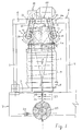
- FIG. 1 is a front elevation view of the machine and figure 2 is an enlarged plan view of said machine, turned 90°, which shows neither the tubular net nor other means shown in figure 1 in the interests of clarity, and as described hereinafter.
- the subject machine comprises a vertical tube (1) having an outer ring (1a) or collar of a suitable material arranged on its top end to make sliding of the tubular net easier -its edge being therefore rounded- and to hold it back to some extent.
- the tube which may be circular, polygonal or otherwise howsoever in shape, stands on a support (2) that turns about a vertical column (3) comprising a circular rod forming part of the framework (4) of the machine, which comprises said column, a vertical column (5) -parallel to column (3) and of like construction- and a horizontal crossbar (6) and (6a) fixed to both columns.
- the framework (4) is upstanding on and fixed to a clamping and shearing device (7) (partially and schematically shown in figure 1).
- the turning support (2) has a short funnel (8) (only shown in figure 1) whose function is to contain the tubular net (9) (figure 1), the creased tubular net being arranged about the tube (1) and is retained by retaining means shown schematically (R) located under the ring (1a) and which press it radially against the tube at various points that are evenly spaced out about the tube or throughout its periphery.
- the tubular net is arranged, and before this the support (2a) and the tube (1b) are first placed in the position shown in phantom in figure 2, which position is obtained by turning said support (2) with its empty tube (1) manually or automatically, as the case may be. Having filled the tube (1b) with the appropriate batch or quantity of tubular net about the same, it is returned to the turning support, manually or automatically, reaching the operative position shown in figure 1 with the tubular net already in place.
- the support (2) and the empty tube (1) are moved out, as shown in phantom in figure 2, to the positions of the tube (1b) and support (2a).
- Two variants are possible: one in which the empty tube is replaced with a tube that has already been filled with the respective batch of tubular net upon the support (2a) and another in which a batch of tubular net is arranged about the empty tube.
- the support is turned in the opposite direction until it reaches the position shown in figure 1 and in figure 2, although the latter does not show the relevant batch of tubular net.
- the support may have another diametrically opposed arm, wherein another tube already filled with the batch of tubular net may stand, thereby enhancing the performance of the machine per unit of time, since eliminating the idle times required to place a new tube having the batch of tubular net.
- the support could evidently carry three or more arms with their respective tubes.
- the machine has two pairs of arms (10) and (11), swinging in opposite directions and on a vertical plane, the top ends of which are articulated to the crossbar (6a) and with two cross shafts (12) and (13) (figure 2) lying within the respective free ends of such arms, supported and guided for rotation between such ends, albeit without axial movement.
- These shafts are provided on the front of the machine with respective grooved pulleys (14) and (15) (schematically shown only in figure 1), and extend into overhanging projections having affixed respective pairs of frustum-of-the-cone rollers (16) and (17) coated in rubber or another material with adherent features, although they might indeed have a rough surface.
- Both pairs of articulated arms (10) and (11) are interlinked by means of a pneumatic cylinder (18), which could be hydraulic and single or double acting cylinder, whose body is articulated between one of the two pairs of arms, in this example between the pair of arms (11), and whose stem is articulated to the other pair of arms, in this example to the pair of arms (10).
- a pneumatic cylinder (18) which could be hydraulic and single or double acting cylinder, whose body is articulated between one of the two pairs of arms, in this example between the pair of arms (11), and whose stem is articulated to the other pair of arms, in this example to the pair of arms (10).
- the gearmotor (19) (only shown in figure 1) causes a gearing (20), comprising four intermeshing cogwheels in this example, to turn in one direction or another, the first and the last of such cogwheels being respectively connected to two shafts to which the two pairs of arms (10) and (11) are in turn articulated, respective grooved pulleys (21) and (22) being connected to such shafts which interlink with the grooved pulleys (14) and (15) through respective drive belts.
- the grooved pulleys (14), (15), (21) and (22) could naturally be replaced with suitable cogwheels and the drive means between the relevant pulleys would then comprise driving chains meshing between such cogwheels.
- Closure and shearing means (23) are provided, shown schematically in figure 1 and forming part of the clamping and shearing device (7), which has a detector (24) for sensing a bag (25) already full of the desired products and closed, which detector governs the gearmotor (19), stopping it when there is no bag (25), which will usually happen when the tubular bag in the tube (1) is depleted or there is a breakdown or malfunction of the pulling means, their driving means and/or the means drawing the pairs of articulated arms to and from each other.
- the top end of the tubular net (9) is lifted and inserted within the tube (1) through its top mouth, running over the edge of the ring (1a) and the tubular net (9) is lowered -inside the tube (1)- until the lower free end projects under the tube (1), whereupon the closure means are applied to such free end, usually in the form of a clamp that is tightly fixed to such free end to close the same.
- the pairs of rollers (16) and (17) lie drawn away from the tube in order to allow such operation and when insertion of the top end of the tubular net in the tube has begun, said two pairs of rollers are applied against the tubular net and, upon the gearmotor (19) being activated to turn in the right direction, the two pairs of rollers turn to raise the outer part of the tubular net thereby to supply it into the tube (1) and the free end of the net is lowered within the tube until it projects under the same.
- Closure means for instance a clamp, are next applied to such free end, and the direction of rotation of the gearmotor is then inverted and the pairs of rollers (16) and (17) thus turn in the opposite direction and thereby cause the outer part of the tubular net to be lowered, the inner part of such net being raised until its lower closed and free end (26) reaches a certain height, forming a bag that is open at the top and lies next to the top unloading area of the product to be packaged.
- Closure means for instance a clamp
- Closure means such as a clamp (27), and other means, such as a clamp (28), separate from and slightly above the clamp (27), are applied to the top end of the bag.
- the pinched net lying midway between both clamps (27) and (28) is sheared by the shearing means of the closure and shearing means (23), and the full bag (25) obtained is thus separated from the rest of the tubular net.
- a label bearing the desired signs and information can, as appropriate, be affixed to the bag and held by the clamp (27) proper or other means (for instance self-adhesive and sealing means).
- the full and closed bags that are obtained may be carried or slid to the temporary storage location by conventional means.
Landscapes
- Engineering & Computer Science (AREA)
- Mechanical Engineering (AREA)
- Containers And Plastic Fillers For Packaging (AREA)
- Making Paper Articles (AREA)
- Treatment Of Fiber Materials (AREA)
- Supplying Of Containers To The Packaging Station (AREA)
- Fish Paste Products (AREA)
- Shaping By String And By Release Of Stress In Plastics And The Like (AREA)
- Manipulator (AREA)
- Auxiliary Devices For And Details Of Packaging Control (AREA)
- Packaging Of Special Articles (AREA)
Applications Claiming Priority (2)
| Application Number | Priority Date | Filing Date | Title |
|---|---|---|---|
| ES09500766A ES2108633B1 (es) | 1995-04-20 | 1995-04-20 | Maquina para obtener bolsas llenas con productos a partir de lotes de malla tubular. |
| ES9500766 | 1995-04-20 |
Publications (3)
| Publication Number | Publication Date |
|---|---|
| EP0738657A2 true EP0738657A2 (de) | 1996-10-23 |
| EP0738657A3 EP0738657A3 (de) | 1997-11-19 |
| EP0738657B1 EP0738657B1 (de) | 1999-11-24 |
Family
ID=8290133
Family Applications (1)
| Application Number | Title | Priority Date | Filing Date |
|---|---|---|---|
| EP96500042A Expired - Lifetime EP0738657B1 (de) | 1995-04-20 | 1996-04-16 | Vorrichtung zum Verpacken von Produkten in Beuteln, ausgehend von einem Vorrat von schlauchförmigem Netz |
Country Status (8)
| Country | Link |
|---|---|
| EP (1) | EP0738657B1 (de) |
| JP (1) | JPH08301210A (de) |
| AT (1) | ATE186884T1 (de) |
| DE (1) | DE69605231T2 (de) |
| DK (1) | DK0738657T3 (de) |
| ES (1) | ES2108633B1 (de) |
| GR (1) | GR3032717T3 (de) |
| PT (1) | PT738657E (de) |
Cited By (8)
| Publication number | Priority date | Publication date | Assignee | Title |
|---|---|---|---|---|
| EP0802113A1 (de) * | 1996-04-17 | 1997-10-22 | Roda Packing, S.A. | Doppelvorrichtung für Verpackungsmaschinen zum Verpacken von Obst |
| WO2002100723A1 (en) * | 2001-06-12 | 2002-12-19 | Sangenic International Limited | Spool for a waste storage device |
| US7743588B2 (en) | 2003-10-23 | 2010-06-29 | Sangenic International Limited | Waste storage device |
| US8662337B2 (en) | 2006-11-16 | 2014-03-04 | Sangenic International Limited | Waste storage device |
| CN108438348A (zh) * | 2018-04-24 | 2018-08-24 | 烟台梦现自动化设备有限公司 | 一种水果网袋撑圆系统 |
| US10214347B2 (en) | 2011-02-28 | 2019-02-26 | Sangenic International Limited | Waste storage device |
| CN112722403A (zh) * | 2021-01-15 | 2021-04-30 | 成都市新享科技有限公司 | 一种塑料发泡网套包装机构 |
| CN112777032A (zh) * | 2021-01-15 | 2021-05-11 | 成都市新享科技有限公司 | 一种以塑料发泡网套为包材的包装机 |
Families Citing this family (1)
| Publication number | Priority date | Publication date | Assignee | Title |
|---|---|---|---|---|
| CN116654355B (zh) * | 2023-07-24 | 2023-09-26 | 成都工业学院 | 一种石榴包装装置 |
Family Cites Families (6)
| Publication number | Priority date | Publication date | Assignee | Title |
|---|---|---|---|---|
| US3553924A (en) * | 1968-04-24 | 1971-01-12 | Swift & Co | Method and apparatus for bagging product |
| SE381172B (sv) * | 1973-01-03 | 1975-12-01 | Pactosan Ab | Anordning for paketering av avfall i en slang |
| US3940906A (en) * | 1974-11-04 | 1976-03-02 | Fmc Corporation | Method of and apparatus for forming packages |
| ES475372A1 (es) * | 1978-11-24 | 1979-04-01 | Dauder Guardiola Agustin | Maquina automatica para la formacion y cerrado en continuo de bolsas de malla obtenidas a partir de red tubular |
| ES8703797A1 (es) * | 1986-05-13 | 1987-03-01 | Roda Packing Sa | Perfeccionamientos en las maquinas envasadoras automaticas de objetos, frutas u hortalizas a granel, en mangas continuas de malla o tubo flexible |
| GB8818365D0 (en) * | 1988-08-02 | 1988-09-07 | Process Improvements Ltd | Cassette containing flexible tubing to be dispensed therefrom |
-
1995
- 1995-04-20 ES ES09500766A patent/ES2108633B1/es not_active Expired - Fee Related
-
1996
- 1996-04-16 DK DK96500042T patent/DK0738657T3/da active
- 1996-04-16 JP JP8094345A patent/JPH08301210A/ja active Pending
- 1996-04-16 AT AT96500042T patent/ATE186884T1/de not_active IP Right Cessation
- 1996-04-16 EP EP96500042A patent/EP0738657B1/de not_active Expired - Lifetime
- 1996-04-16 PT PT96500042T patent/PT738657E/pt unknown
- 1996-04-16 DE DE69605231T patent/DE69605231T2/de not_active Expired - Fee Related
-
2000
- 2000-02-21 GR GR20000400416T patent/GR3032717T3/el unknown
Cited By (13)
| Publication number | Priority date | Publication date | Assignee | Title |
|---|---|---|---|---|
| EP0802113A1 (de) * | 1996-04-17 | 1997-10-22 | Roda Packing, S.A. | Doppelvorrichtung für Verpackungsmaschinen zum Verpacken von Obst |
| ES2130038A1 (es) * | 1996-04-17 | 1999-06-16 | Roda Packing Sa | Dispositivo de cabezal doble para el envasado de fruta, aplicable a maquinas embaladoras. |
| US8484936B2 (en) | 2001-06-12 | 2013-07-16 | Sangenic International Limited | Spool for a waste storage device |
| AU2002319388B2 (en) * | 2001-06-12 | 2007-12-06 | Sangenic International Limited | Spool for a waste storage device |
| CZ300626B6 (cs) * | 2001-06-12 | 2009-07-01 | Sangenic International Limited | Cívka a kazeta pro zarízení k ukládání odpadu, zarízení k ukládání odpadu a zpusob ukládání hadicové fólie na cívku |
| WO2002100723A1 (en) * | 2001-06-12 | 2002-12-19 | Sangenic International Limited | Spool for a waste storage device |
| US7743588B2 (en) | 2003-10-23 | 2010-06-29 | Sangenic International Limited | Waste storage device |
| US10669095B2 (en) | 2003-10-23 | 2020-06-02 | Sangenic International Ltd. | Waste storage device |
| US8662337B2 (en) | 2006-11-16 | 2014-03-04 | Sangenic International Limited | Waste storage device |
| US10214347B2 (en) | 2011-02-28 | 2019-02-26 | Sangenic International Limited | Waste storage device |
| CN108438348A (zh) * | 2018-04-24 | 2018-08-24 | 烟台梦现自动化设备有限公司 | 一种水果网袋撑圆系统 |
| CN112722403A (zh) * | 2021-01-15 | 2021-04-30 | 成都市新享科技有限公司 | 一种塑料发泡网套包装机构 |
| CN112777032A (zh) * | 2021-01-15 | 2021-05-11 | 成都市新享科技有限公司 | 一种以塑料发泡网套为包材的包装机 |
Also Published As
| Publication number | Publication date |
|---|---|
| EP0738657B1 (de) | 1999-11-24 |
| JPH08301210A (ja) | 1996-11-19 |
| ES2108633R (de) | 1998-01-01 |
| ES2108633B1 (es) | 1998-07-01 |
| DK0738657T3 (da) | 2000-05-15 |
| DE69605231T2 (de) | 2000-07-13 |
| ATE186884T1 (de) | 1999-12-15 |
| PT738657E (pt) | 2000-05-31 |
| EP0738657A3 (de) | 1997-11-19 |
| ES2108633A2 (es) | 1997-12-16 |
| GR3032717T3 (en) | 2000-06-30 |
| DE69605231D1 (de) | 1999-12-30 |
Similar Documents
| Publication | Publication Date | Title |
|---|---|---|
| US3431706A (en) | Floral sacker | |
| EP0738657B1 (de) | Vorrichtung zum Verpacken von Produkten in Beuteln, ausgehend von einem Vorrat von schlauchförmigem Netz | |
| CA2249849A1 (en) | Bag filling apparatus and method | |
| ES2158410T3 (es) | Dispositivo de vaciado para producto a granel suelto. | |
| US5502949A (en) | Fruit bin filler | |
| CN218704047U (zh) | 绞股蓝配方茶分装包装机 | |
| EP1419850A2 (de) | Vorrichtungen und Verfahren zum Trennen und Einsetzen einer Dichtung | |
| EP0743251B1 (de) | Verfahren zum Erzeugen von mit Gegenständen gefüllten Packungen mittels eines kontinuierlichen Netzschlauches | |
| US3182611A (en) | Apparatus for making and packaging ice cream sandwiches | |
| EP0579051A2 (de) | System zur aseptischen Entleerung von flexiblen Nahrungsmittelbehältern | |
| EP0742149B1 (de) | Verfahren zum Verpacken von Produkten in Beuteln, ausgehend von einem Vorrat von schlauchförmigem Netz | |
| DE3424233C2 (de) | ||
| US20240083607A1 (en) | Apparatus and method for products packaging | |
| EP0885806A1 (de) | Verfahren und Vorrichtung zum Verpacken von Früchten und dergleichen in Beuteln | |
| US2763973A (en) | Method of packaging tobacco | |
| DE3038115A1 (de) | Packvorrichtung | |
| DE4116311A1 (de) | Automatische sackanhaengung sowie verfahren dazu | |
| CN213503242U (zh) | 分装机物料打散装置 | |
| DE2131126C3 (de) | Vorrichtung zum Öffnen von Beuteln | |
| US3698155A (en) | Bag support assembly | |
| CN213263192U (zh) | 一种新型包装机抬升装置 | |
| CN221554175U (zh) | 一种食用菌菌棒装袋扎口一体机 | |
| CN114435683B (zh) | 一种生物用粉末药品的装罐设备 | |
| CN219948717U (zh) | 螺旋包装机 | |
| US2259093A (en) | Supply bin |
Legal Events
| Date | Code | Title | Description |
|---|---|---|---|
| PUAI | Public reference made under article 153(3) epc to a published international application that has entered the european phase |
Free format text: ORIGINAL CODE: 0009012 |
|
| AK | Designated contracting states |
Kind code of ref document: A2 Designated state(s): AT BE CH DE DK FI FR GB GR IE IT LI NL PT SE |
|
| PUAL | Search report despatched |
Free format text: ORIGINAL CODE: 0009013 |
|
| AK | Designated contracting states |
Kind code of ref document: A3 Designated state(s): AT BE CH DE DK FI FR GB GR IE IT LI NL PT SE |
|
| 17P | Request for examination filed |
Effective date: 19980429 |
|
| 17Q | First examination report despatched |
Effective date: 19980724 |
|
| GRAG | Despatch of communication of intention to grant |
Free format text: ORIGINAL CODE: EPIDOS AGRA |
|
| GRAG | Despatch of communication of intention to grant |
Free format text: ORIGINAL CODE: EPIDOS AGRA |
|
| GRAH | Despatch of communication of intention to grant a patent |
Free format text: ORIGINAL CODE: EPIDOS IGRA |
|
| GRAH | Despatch of communication of intention to grant a patent |
Free format text: ORIGINAL CODE: EPIDOS IGRA |
|
| GRAA | (expected) grant |
Free format text: ORIGINAL CODE: 0009210 |
|
| AK | Designated contracting states |
Kind code of ref document: B1 Designated state(s): AT BE CH DE DK FI FR GB GR IE IT LI NL PT SE |
|
| REF | Corresponds to: |
Ref document number: 186884 Country of ref document: AT Date of ref document: 19991215 Kind code of ref document: T |
|
| REG | Reference to a national code |
Ref country code: CH Ref legal event code: EP |
|
| REF | Corresponds to: |
Ref document number: 69605231 Country of ref document: DE Date of ref document: 19991230 |
|
| REG | Reference to a national code |
Ref country code: IE Ref legal event code: FG4D |
|
| ITF | It: translation for a ep patent filed | ||
| REG | Reference to a national code |
Ref country code: CH Ref legal event code: NV Representative=s name: INTERPAT LAW AG |
|
| ET | Fr: translation filed | ||
| PGFP | Annual fee paid to national office [announced via postgrant information from national office to epo] |
Ref country code: GB Payment date: 20000412 Year of fee payment: 5 |
|
| PGFP | Annual fee paid to national office [announced via postgrant information from national office to epo] |
Ref country code: PT Payment date: 20000414 Year of fee payment: 5 |
|
| PGFP | Annual fee paid to national office [announced via postgrant information from national office to epo] |
Ref country code: GR Payment date: 20000417 Year of fee payment: 5 Ref country code: DE Payment date: 20000417 Year of fee payment: 5 |
|
| PGFP | Annual fee paid to national office [announced via postgrant information from national office to epo] |
Ref country code: FR Payment date: 20000426 Year of fee payment: 5 |
|
| PGFP | Annual fee paid to national office [announced via postgrant information from national office to epo] |
Ref country code: SE Payment date: 20000427 Year of fee payment: 5 Ref country code: DK Payment date: 20000427 Year of fee payment: 5 Ref country code: CH Payment date: 20000427 Year of fee payment: 5 Ref country code: AT Payment date: 20000427 Year of fee payment: 5 |
|
| PGFP | Annual fee paid to national office [announced via postgrant information from national office to epo] |
Ref country code: NL Payment date: 20000428 Year of fee payment: 5 Ref country code: IE Payment date: 20000428 Year of fee payment: 5 Ref country code: FI Payment date: 20000428 Year of fee payment: 5 |
|
| REG | Reference to a national code |
Ref country code: DK Ref legal event code: T3 |
|
| REG | Reference to a national code |
Ref country code: PT Ref legal event code: SC4A Free format text: AVAILABILITY OF NATIONAL TRANSLATION Effective date: 20000223 |
|
| PGFP | Annual fee paid to national office [announced via postgrant information from national office to epo] |
Ref country code: BE Payment date: 20000622 Year of fee payment: 5 |
|
| PLBE | No opposition filed within time limit |
Free format text: ORIGINAL CODE: 0009261 |
|
| STAA | Information on the status of an ep patent application or granted ep patent |
Free format text: STATUS: NO OPPOSITION FILED WITHIN TIME LIMIT |
|
| 26N | No opposition filed | ||
| PG25 | Lapsed in a contracting state [announced via postgrant information from national office to epo] |
Ref country code: IE Free format text: LAPSE BECAUSE OF NON-PAYMENT OF DUE FEES Effective date: 20010416 Ref country code: GB Free format text: LAPSE BECAUSE OF NON-PAYMENT OF DUE FEES Effective date: 20010416 Ref country code: FI Free format text: LAPSE BECAUSE OF NON-PAYMENT OF DUE FEES Effective date: 20010416 Ref country code: DK Free format text: LAPSE BECAUSE OF NON-PAYMENT OF DUE FEES Effective date: 20010416 Ref country code: AT Free format text: LAPSE BECAUSE OF NON-PAYMENT OF DUE FEES Effective date: 20010416 |
|
| PG25 | Lapsed in a contracting state [announced via postgrant information from national office to epo] |
Ref country code: SE Free format text: LAPSE BECAUSE OF NON-PAYMENT OF DUE FEES Effective date: 20010417 |
|
| PG25 | Lapsed in a contracting state [announced via postgrant information from national office to epo] |
Ref country code: FR Free format text: THE PATENT HAS BEEN ANNULLED BY A DECISION OF A NATIONAL AUTHORITY Effective date: 20010430 Ref country code: BE Free format text: LAPSE BECAUSE OF NON-PAYMENT OF DUE FEES Effective date: 20010430 |
|
| PG25 | Lapsed in a contracting state [announced via postgrant information from national office to epo] |
Ref country code: LI Free format text: LAPSE BECAUSE OF NON-PAYMENT OF DUE FEES Effective date: 20010515 Ref country code: CH Free format text: LAPSE BECAUSE OF NON-PAYMENT OF DUE FEES Effective date: 20010515 |
|
| BERE | Be: lapsed |
Owner name: S.A. TALLERES DAUMAR Effective date: 20010430 |
|
| PG25 | Lapsed in a contracting state [announced via postgrant information from national office to epo] |
Ref country code: PT Free format text: LAPSE BECAUSE OF NON-PAYMENT OF DUE FEES Effective date: 20011031 Ref country code: GR Free format text: LAPSE BECAUSE OF NON-PAYMENT OF DUE FEES Effective date: 20011031 |
|
| PG25 | Lapsed in a contracting state [announced via postgrant information from national office to epo] |
Ref country code: NL Free format text: LAPSE BECAUSE OF NON-PAYMENT OF DUE FEES Effective date: 20011101 |
|
| EUG | Se: european patent has lapsed |
Ref document number: 96500042.5 |
|
| REG | Reference to a national code |
Ref country code: DK Ref legal event code: EBP |
|
| GBPC | Gb: european patent ceased through non-payment of renewal fee |
Effective date: 20010416 |
|
| REG | Reference to a national code |
Ref country code: CH Ref legal event code: PL |
|
| NLV4 | Nl: lapsed or anulled due to non-payment of the annual fee |
Effective date: 20011101 |
|
| PG25 | Lapsed in a contracting state [announced via postgrant information from national office to epo] |
Ref country code: DE Free format text: LAPSE BECAUSE OF NON-PAYMENT OF DUE FEES Effective date: 20020201 |
|
| REG | Reference to a national code |
Ref country code: FR Ref legal event code: ST |
|
| REG | Reference to a national code |
Ref country code: IE Ref legal event code: MM4A |
|
| REG | Reference to a national code |
Ref country code: PT Ref legal event code: MM4A Free format text: LAPSE DUE TO NON-PAYMENT OF FEES Effective date: 20011031 |
|
| PG25 | Lapsed in a contracting state [announced via postgrant information from national office to epo] |
Ref country code: IT Free format text: LAPSE BECAUSE OF NON-PAYMENT OF DUE FEES;WARNING: LAPSES OF ITALIAN PATENTS WITH EFFECTIVE DATE BEFORE 2007 MAY HAVE OCCURRED AT ANY TIME BEFORE 2007. THE CORRECT EFFECTIVE DATE MAY BE DIFFERENT FROM THE ONE RECORDED. Effective date: 20050416 |