EP0579100A1 - Procédé et dispositif de correction de phase en bande de base dans un récepteur "PSK" - Google Patents
Procédé et dispositif de correction de phase en bande de base dans un récepteur "PSK" Download PDFInfo
- Publication number
- EP0579100A1 EP0579100A1 EP93110864A EP93110864A EP0579100A1 EP 0579100 A1 EP0579100 A1 EP 0579100A1 EP 93110864 A EP93110864 A EP 93110864A EP 93110864 A EP93110864 A EP 93110864A EP 0579100 A1 EP0579100 A1 EP 0579100A1
- Authority
- EP
- European Patent Office
- Prior art keywords
- phase
- signal
- output
- control
- loop
- Prior art date
- Legal status (The legal status is an assumption and is not a legal conclusion. Google has not performed a legal analysis and makes no representation as to the accuracy of the status listed.)
- Granted
Links
- 238000000034 method Methods 0.000 title claims abstract description 102
- 238000012937 correction Methods 0.000 title description 3
- 230000003044 adaptive effect Effects 0.000 claims abstract description 11
- 238000011084 recovery Methods 0.000 claims description 35
- 230000008569 process Effects 0.000 claims description 24
- 238000011156 evaluation Methods 0.000 claims description 11
- 230000009466 transformation Effects 0.000 claims description 10
- 238000012545 processing Methods 0.000 claims description 9
- 238000005070 sampling Methods 0.000 claims description 6
- 230000000295 complement effect Effects 0.000 claims description 2
- 230000006641 stabilisation Effects 0.000 claims 1
- 238000011105 stabilization Methods 0.000 claims 1
- 102100026758 Serine/threonine-protein kinase 16 Human genes 0.000 description 14
- 101710184778 Serine/threonine-protein kinase 16 Proteins 0.000 description 14
- 230000005540 biological transmission Effects 0.000 description 14
- 230000008878 coupling Effects 0.000 description 11
- 238000010168 coupling process Methods 0.000 description 11
- 238000005859 coupling reaction Methods 0.000 description 11
- 238000011161 development Methods 0.000 description 9
- 230000018109 developmental process Effects 0.000 description 9
- 238000004891 communication Methods 0.000 description 8
- 230000008901 benefit Effects 0.000 description 7
- 230000006870 function Effects 0.000 description 5
- 230000008929 regeneration Effects 0.000 description 5
- 238000011069 regeneration method Methods 0.000 description 5
- 238000010586 diagram Methods 0.000 description 3
- 238000001228 spectrum Methods 0.000 description 3
- 238000011144 upstream manufacturing Methods 0.000 description 3
- 238000007476 Maximum Likelihood Methods 0.000 description 2
- 238000006243 chemical reaction Methods 0.000 description 2
- 230000001419 dependent effect Effects 0.000 description 2
- 238000013461 design Methods 0.000 description 2
- 230000000694 effects Effects 0.000 description 2
- 238000005516 engineering process Methods 0.000 description 2
- 238000001914 filtration Methods 0.000 description 2
- 238000007493 shaping process Methods 0.000 description 2
- 230000003595 spectral effect Effects 0.000 description 2
- 230000001360 synchronised effect Effects 0.000 description 2
- 230000008859 change Effects 0.000 description 1
- 238000012512 characterization method Methods 0.000 description 1
- 230000007423 decrease Effects 0.000 description 1
- 230000002349 favourable effect Effects 0.000 description 1
- 230000014509 gene expression Effects 0.000 description 1
- 238000013507 mapping Methods 0.000 description 1
- 238000012986 modification Methods 0.000 description 1
- 230000004048 modification Effects 0.000 description 1
- 238000012544 monitoring process Methods 0.000 description 1
- 238000010606 normalization Methods 0.000 description 1
- 238000005457 optimization Methods 0.000 description 1
- 230000000737 periodic effect Effects 0.000 description 1
- 238000003672 processing method Methods 0.000 description 1
- 238000013139 quantization Methods 0.000 description 1
- 238000011160 research Methods 0.000 description 1
- 230000035945 sensitivity Effects 0.000 description 1
- 230000008054 signal transmission Effects 0.000 description 1
- 238000004088 simulation Methods 0.000 description 1
Images

Classifications
-
- H—ELECTRICITY
- H04—ELECTRIC COMMUNICATION TECHNIQUE
- H04L—TRANSMISSION OF DIGITAL INFORMATION, e.g. TELEGRAPHIC COMMUNICATION
- H04L27/00—Modulated-carrier systems
- H04L27/18—Phase-modulated carrier systems, i.e. using phase-shift keying
- H04L27/22—Demodulator circuits; Receiver circuits
- H04L27/233—Demodulator circuits; Receiver circuits using non-coherent demodulation
- H04L27/2332—Demodulator circuits; Receiver circuits using non-coherent demodulation using a non-coherent carrier
-
- H—ELECTRICITY
- H04—ELECTRIC COMMUNICATION TECHNIQUE
- H04L—TRANSMISSION OF DIGITAL INFORMATION, e.g. TELEGRAPHIC COMMUNICATION
- H04L27/00—Modulated-carrier systems
- H04L27/0014—Carrier regulation
- H04L2027/0024—Carrier regulation at the receiver end
- H04L2027/0026—Correction of carrier offset
- H04L2027/0028—Correction of carrier offset at passband only
-
- H—ELECTRICITY
- H04—ELECTRIC COMMUNICATION TECHNIQUE
- H04L—TRANSMISSION OF DIGITAL INFORMATION, e.g. TELEGRAPHIC COMMUNICATION
- H04L27/00—Modulated-carrier systems
- H04L27/0014—Carrier regulation
- H04L2027/0024—Carrier regulation at the receiver end
- H04L2027/0026—Correction of carrier offset
- H04L2027/003—Correction of carrier offset at baseband only
-
- H—ELECTRICITY
- H04—ELECTRIC COMMUNICATION TECHNIQUE
- H04L—TRANSMISSION OF DIGITAL INFORMATION, e.g. TELEGRAPHIC COMMUNICATION
- H04L27/00—Modulated-carrier systems
- H04L27/0014—Carrier regulation
- H04L2027/0044—Control loops for carrier regulation
- H04L2027/0053—Closed loops
- H04L2027/0055—Closed loops single phase
-
- H—ELECTRICITY
- H04—ELECTRIC COMMUNICATION TECHNIQUE
- H04L—TRANSMISSION OF DIGITAL INFORMATION, e.g. TELEGRAPHIC COMMUNICATION
- H04L27/00—Modulated-carrier systems
- H04L27/0014—Carrier regulation
- H04L2027/0044—Control loops for carrier regulation
- H04L2027/0053—Closed loops
- H04L2027/0057—Closed loops quadrature phase
Definitions
- the invention relates to a method for carrier recovery in the demodulation of digitally modulated signals according to the preamble of patent claim 1 and arrangements for carrying out the method according to the preamble of patent claims 8 and 9.
- Methods and arrangements of this type are used in the field of communication technology, for example in cooperative or non-cooperative digital demodulators for digital signals with hard or soft keying or in receivers with digital intermediate frequency processing.
- Digital transmission methods have become increasingly important in the field of communication technology in recent decades.
- the reasons for the growing spread of digital transmission methods are the enormous increase in digitally available source data, the trend to digitally display the originally analog source data and not least the increased basic research in digital signal processing.
- the transmission of messages over long distances can basically take place either with the help of broadband cables, via satellites or via the ionospheric short-wave radio channel (HF channel).
- HF channel ionospheric short-wave radio channel
- the RF channel was primarily intended for the transmission of analog source signals.
- complicated adaptive control and signal processing methods can be implemented at reasonable prices that are necessary for the reception and demodulation of digitally modulated transmissions in the shortwave range.
- the RF channel is therefore becoming increasingly important as a medium for the transmission of messages from digitally modulated programs.
- the advantages of a message transmission via shortwave are, among other things, the relatively low expenditure, the short expenditure of time for the connection establishment and the possibility of a mobile operation.
- the modulation means mapping the information into a signal form that is suitable for the transmission of messages over longer distances.
- the information is impressed on a carrier signal, which then either reaches the message receiver as a guided wave within a waveguide (cable) or as a radiated wave.
- the modulated signal is either demodulated directly at the receiving frequency or at an intermediate frequency position.
- Demodulation means the best possible recovery of the original information and is to be understood as an inverse process to the modulation.
- analogue i.e. continuous time and value of digital, i.e. Time and state discrete modulation methods.
- the digital methods use binary states for modulating the carrier signal.
- the binary states of the source data stream are represented as discrete characteristic states of the carrier signal.
- Umtast Kunststoff Shift Keying
- FSK A mplitude- S hift- K eying
- FSK FSK
- PSK P Hare S hift- K eying
- the step speed or the step rate (“symbol rate”) v s of the digital modulation method indicates the number of changes in the characteristic state per second and has the unit of measure baud (Bd).
- the signal is free from intersymbol interference, but has an infinitely wide frequency band and is therefore less for transmission well suited. This can be remedied by softly touching the second Nyquist condition. This means that the maxima and the zero crossings of a pulse train are preserved if their spectrum has a falling edge that runs symmetrically to the cutoff frequency.
- the PSK methods have found great importance in satellite radio, microwave and wired communication systems because of their lower sensitivity to noise interference. For the same error probability of the demodulated data with the optimal receiver structures presupposed in each case, these methods require a lower signal-to-noise ratio than conventional FSK and ASK methods.
- both sidebands must be transmitted.
- the carrier is suppressed and must be recovered during demodulation using special processes.
- methods of reference and differential coding are used. The latter have the advantage that they can be used for demodulation need only one AFC (A utomatic- F requency- C ontrol) circuit for estimating the carrier frequency.
- the complex MPSK symbols exp (j2 ⁇ k / M) are then formed, which define the corresponding phase states.
- the necessary pulse shaping for soft keying is done by filtering the complex MPSK symbols, for example with the help of a root-raised cosine filter.
- the quaternary method QPSK Q uaternary- P Hare S hift- K eying
- Methods for four-phase shift keying are also known, in which the 180 ° jumps are composed of two 90 ° phase jumps which take place at half the step speed.
- the required main selection and demodulation of the received signals usually take place in a lower intermediate frequency (IF) position, since the necessary filters of higher quality and demodulation can be implemented there with less effort.
- the IF signal is a real bandpass signal at the center frequency f IF .
- the IF position cannot be lowered arbitrarily.
- Digital demodulation for example of PSK transmissions in the shortwave range, is, however, conceivable due to the relatively small bandwidth of B PSK ⁇ 5 kHz with reasonable computing effort.
- a quadrature receiver it is possible, for example, to generate a 0-IF PSK signal ("baseband signal”) with a very low residual carrier frequency f R , which is outstandingly suitable for further digital processing.
- the quadrature receiver differs from the synchronous receiver in that the oscillating frequency f O is not synchronized with the receiving frequency f IF .
- the attempt is generally made to keep the residual carrier frequency f R always small in comparison to the low-pass bandwidth B, which in turn is generally chosen to be equal to the signal bandwidth for reasons of noise. No mirror frequencies arise when the bandpass spectrum is shifted.
- the main selection for the 0-IF signal is carried out by two low-pass filters for the real and imaginary parts I, Q of the complex baseband signal (I: I n-phase signal; Q: quadrature signal).
- the information for demodulation can be derived from the complex signal pointer in the baseband. For example, the amplitude of the complex baseband pointer is used for amplitude demodulation.
- the advantage of this method is that the message to be demodulated has almost been freed from the carrier frequency, ie the signal pointer rotating slowly with the residual carrier frequency f R carries all the information necessary for demodulating the message.
- the complex baseband signal reaches the functional units carrier recovery and step clock regeneration.
- the functional unit for carrier recovery has the task of estimating the carrier frequency and phase of the broadcast and - after determining the frequency - eliminating the phase with the aid of a phase rotating element. It is thus possible to bring the coordinate system of the IQ baseband signals rotating with the residual carrier frequency f R to a standstill.
- the functional unit of the step clock regeneration provides estimates for the unknown frequency and phase position the step measure.
- the symbols are derived from the IQ signals in the decision maker, who may have installed an additional interpolation unit.
- the symbols can then be assessed in synchronism with the step clock with the aid of a phase or eye diagram representation with regard to their decoding quality.
- the IQ signals can also be examined in front of the decision maker with the help of an eye diagram representation with regard to the optimal decision time.
- the methods for carrier recovery and step cycle regeneration can be implemented using either recursive or non-recursive methods.
- the recursive methods are often referred to as F eed B ack (FB) process.
- FB F eed B ack
- the maximum of the log likelihood function is calculated using the zero of its 1st derivative. This procedure is reflected in recursive structures, in which an error size is defined with the help of an error detector, which is optimized to zero within the recursion. In this way, the zero of the first derivative of the log-likelihood function of the carrier and step clock estimation is found, for example with the aid of a gradient method.
- the FB methods have the advantage that they can also detect minor changes in the carrier phase and the symbol timing.
- the decision-directed carrier recovery process requires knowledge of the exact symbol timing.
- the power-of-N carrier recovery process uses a () N nonlinearity to generate a spectral component at the carrier frequency.
- the decision-directed process represents a digital variant of the aforementioned COSTAS loop in the 0-IF position, which, however, does not require a low-pass filter in the loop. You can see in the structure shown the signal link to eliminate the data dependency and the inclusion of the decision maker in the loop. With the power-of-N method, the loop snaps onto the Nth harmonic of the carrier frequency.
- the decision-making loop requires a medium to good signal-to-noise ratio of the input signal. Both loops have a sinusoidal phase detector characteristic.
- the decision-making methods for carrier recovery have problems with difficult transmission channels (e.g. RF channel).
- the classic analog COSTAS loop is suitable for carrier recovery of BPSK signals in the bandpass range. Two low pass filters are required in the loop.
- the COSTAS loop has a quadratic level dependency. The acquisition behavior of the loop is influenced by the sinusoidal phase detector characteristic. For higher-level PSK processes, modifications to the structure are required, which represent a considerable outlay on implementation.
- the hybrid tanlock loop consists of an analog front end for mixing into an intermediate frequency position and two clock-controlled analog-digital converters.
- the information for clock control of the A / D converters is obtained with the aid of a special phase detector, a control filter and a clock generation unit.
- the digital part of the carrier recovery thus works with a variable sampling clock.
- the data dependency is eliminated by multiplying the phase by the factor M (M-PSK) and a modulo 2 ⁇ characteristic.
- M-PSK the factor M
- ⁇ o the angular frequency
- the sawtooth-shaped phase detector characteristic with a large linearity range is advantageous for the acquisition behavior.
- the tanlock loop works without level coupling.
- step-independent carrier recovery processes include the aforementioned COSTAS loop, the squaring loop and the quadrupling loop process. These methods are mainly used in analog PSK receivers for real bandpass signals.
- the object of the invention is, on the one hand, to provide a robust method for recursive carrier recovery, which does not require knowledge of the step clock timing and does not work with data support and which, in particular, meets the requirements for receiving digitally modulated signals in the shortwave range.
- arrangements for carrying out such a method are to be specified which are particularly simple in their structure.
- the coordinate transformation of the in-phase and Quadrature signals I, Q (alternative I) or the baseband signal x k (alternative II) are carried out from the Cartesian coordinate display to the polar coordinate display using the known CORDIC algorithm (see, for example: Yu Hen Hu: “The Quantization Effects of the CORDIC Algorithm "; in: IEEE TRANSACTIONS ON SIGNAL PROCESSING, Vol. 40, No. 4, April 1992, pp. 834-844).
- this preferred embodiment of the invention provides that the coordinate transformer (KT) operates according to the CORDIC algorithm.
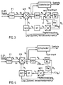
- the carrier recovery arrangement in FIG. 1 is constructed in the form of a control loop and is suitable for carrying out the inventive method according to alternative I.
- the baseband signal (“O-IF signal”), which has a residual carrier of frequency f R and phase ⁇ R , is applied to a filter F1, for example an optimal or main selection filter.
- a filter F1 for example an optimal or main selection filter.
- Consisting of the real part Re and imaginary part Im existing complex filtered signal k x is a quadrature mixer QM with the (in each case by 90 ° phase with each other) output signals v k a numerically controlled reference oscillator NCO ( "N umerical- C ontrolled- O scillator”) complex quadrature mixed .
- NCO numerically controlled reference oscillator
- the in-phase and quadrature output signals I and Q of the quadrature mixer QM thus generated, which together form the complex output signal y k , are sent to a decision maker for further evaluation.
- the decision maker is also supplied with a step clock regeneration unit (not shown) for determining the step clock of the program to be demodulated.
- a step clock regeneration unit (not shown) for determining the step clock of the program to be demodulated.
- the I and Q signals of the quadrature mixer QM are also fed to the control loop already mentioned, namely a coordinate transformer KT, which transforms the I and Q signals shown in Cartesian coordinates into a polar coordinate representation characterized by magnitude A k and phase ⁇ k and who uses the CORDIC algorithm, which is known per se, for this transformation.
- the modulation signal-independent phase error signal ⁇ k appears at the output of this unit and is fed to a control filter.
- the design of this filter imprints the dynamics and the noise behavior on the control loop.
- a control signal c k derived from the phase error signal il k appears , which is fed to the control input of the reference oscillator NCO and which adjusts its frequency f o or phase ⁇ o .
- This recursive readjustment process successively brings the frequency f o and the phase ⁇ o of the reference oscillator NCO into line with the frequency f R and the phase ⁇ R of the residual carrier of the baseband signal x k .
- a monitoring line also leads from the reference oscillator NCO to a control unit (not shown) which monitors the state of the control loop ("Loop state”) checked and possibly a sign correction in the output data stream of the decision maker.
- the carrier recovery arrangement in FIG. 2 differs from that in FIG. 1 in that the coordinate transformer KT is not arranged in the control loop, but is connected upstream. This arrangement is suitable for carrying out the method according to alternative II.
- the output of the coordinate transformer KT carrying the phase ⁇ xk of the filtered complex baseband signal x k is connected to one input of a subtractor SUB, the other input of which is connected to the output of a phase accumulator AKKU, which generates a reference phase ⁇ o .
- the difference ⁇ between the two adjacent phases ⁇ xk and ⁇ o is formed in the subtractor SUB and then sent to a decision maker, who uses the step clock also supplied to him to determine the sequence of symbols from the phase difference signal ⁇ , which then corresponds to the (not shown) Decoders can be fed for further processing.
- phase difference signal ⁇ of the subtractor SUB is also fed to the control loop, specifically that already in FIG. 1 described unit MP1, Mod-2 ⁇ , which frees the phase difference ⁇ from the modulation signal dependency, ie data dependency.
- the modulation signal-independent phase error signal ⁇ k generated in this way is fed to a control filter RF which gives a corresponding control signal to the input of the phase accumulator AKKU with which the phase ⁇ o of the phase accumulator is adjusted.
- the phase ⁇ o of the phase accumulator AKKU is successively brought into agreement with the phase ⁇ xk of the baseband signal x k .
- a control line also goes from the phase accumulator AKKU to a control unit (not shown), in which the state of the control loop is monitored and, if necessary, a sign correction is carried out in the output data stream of the decision maker.
- the special feature of this embodiment is that the control loop works completely in the phase plane.
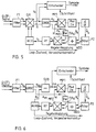
- the carrier recovery arrangement in FIG. 3, which is a particularly advantageous first development of the arrangement according to FIG. 1 differs from this in that a level coupling is additionally provided to achieve an adaptive behavior of the control loop (with regard to the similarities in the structure of the arrangements, reference is made to the description of the figures in FIG. 1).
- the coordinate transformer works according to the CORDIC algorithm known per se and delivers both the phase ⁇ k and the magnitude A k of the complex output signal y k of the complex quadrature mixer QM on the output side. While the phase ⁇ k in the unit (MP1, Mod -2 ⁇ ) is freed from the modulation signal dependency, the amount A k via an evaluation unit BW fed to a multiplier MP2 and there multiplied the weighted amount F (A k ) by the modulation signal-independent phase error signal ⁇ k .
- the error signal ⁇ k generated in this way at the output of the multiplier MP2 is then fed to the control filter RF, which generates a control signal c k as a function of the error signal ⁇ k , which is applied to the control input of the reference oscillator NCO.
- FIG. 3 shows embodiments of the method according to the invention and the arrangements according to the invention which meet the requirements, in particular when receiving MPSK signals in the shortwave range, and which can be understood as quasi-optimal structures in the sense of the maximum likelihood (ML) criterion.
- ML maximum likelihood
- the modulation signal dependency of the phase ⁇ k is eliminated by multiplication by the factor M and a subsequent modulo 2 ⁇ characteristic and results in the phase error signal ⁇ k which is independent of the modulation signal by:
- the CORDIC loop also offers the option of using special optimization methods to manipulate the signal level during the acquisition phase so that the loop can be locked more quickly. When the CORDIC loop is locked, the following is obtained for the phase error signal:
- the result is a modulo 2 ⁇ / M sawtooth curve.
- the large linearity range of the CORDIC phase detector leads to better acquisition behavior, larger capture areas, larger disengagement areas (pull-out areas) and cheaper Behavior regarding hangups with otherwise the same optimal behavior of the carrier recovery.
- Another advantage of the CORDIC loop is the structural independence with higher-level MPSK processes. In the MPSK method, the influence of the modulation signal or data in the control signal is eliminated by multiplying by the factor M.
- the factor M is multiplied by a simple one Shift operation and the representation of the modulo-2 ⁇ characteristic by the two's complement representation of the number range and a corresponding normalization in the reference oscillator NCO. Taking into account the acquisition properties and other boundary conditions, the CORDIC loop is therefore cheaper globally than the COSTAS loop described above.
- the carrier recovery arrangement in FIG. 4 represents another development of the arrangement according to FIG. 1, which can be used for carrier recovery in QAM-modulated signals.
- the unit for relieving the phase ⁇ k supplied by the upstream CORDIC coordinator transformer is implemented by a QAM non-linearity unit QAM-NL.
- the modulation-signal-independent phase error signal ⁇ k generated in this way is then - as shown in FIG. 3 - placed on the multiplier MP2 and multiplied there by the evaluated magnitude signal F (A k ) of the CORDIC coordinate transformer.
- the carrier recovery arrangement in FIG. 5 differs from that in FIG. 3 in that the control loop has also been expanded to include a circuit for automatic frequency control (AFC: A utomatic- F requency- C ontrol).
- the unit consists of a time differentiator d / dt and a downstream filter F2.
- the phase error signal ⁇ k which is independent of the modulation signal, is supplied to the time differentiator d / dt, which generates the first time derivative ⁇ k of this signal and supplies it to the filter F2.
- the filtered first time derivative ⁇ k from ⁇ k is then fed to an adder ADD and added there to the phase error signal ⁇ k .
- the sum output signal of the adder ADD is then fed together with the weighted magnitude signal F (A k ) of the CORDIC transformer to the multiplier MP2, in which the error signal ⁇ k is derived from these signals.
- the carrier recovery arrangement in FIG. 6 differs from the arrangement according to FIG. 2 in that, on the one hand, in addition to identifying an adaptive behavior of the control loop, the amount F (A k ) of the filtered complex baseband signal x k evaluated in an evaluation unit BW is coupled in, and on the other hand that the amount shown in FIG. 5 already described additional circuit (d / dt, F2) for automatic frequency control ("AFC control loop") is provided.
- a coordinate transformer as in FIG. 3-5, a CORDIC transformer is provided.
- the filtered, time-differentiated signal ⁇ k is then ⁇ in an adder ADD to the phase error signal k is added and the sum signal of the adder ADD is supplied to the multiplier MP2, which also includes the estimated by the evaluation unit BW amount signal A xk of the filtered complex baseband signal x k is forwarded.
- the error signal ⁇ k present at the output of the multiplier MP2 is then fed to the control filter RF, which uses it to generate the control signal c k for the phase accumulator ACCU.
- the CORDIC loop in the phase plane (FIG. 2 and FIG. 6) is advantageous for applications of the methods for carrier recovery with the aid of digital signal processors, since the sin and cos tables in the reference oscillator NCO can be saved, and instead a simple phase accumulator can be used.
- the recursive structures of the above-described COSTAS loop for complex baseband signals and the working of the invention recursive structures with or without Pegeleinkopplung can be summarized in an equivalent circuit diagram of a basic structure of a d igitalen P Hare L ocked L oop (DPPL) consisting of the functional units phase detector, control filter and a numerically controlled There is an oscillator for generating the complex reference pointer.
- DPPL d igitalen P Hare L ocked L oop
- the phase detector generally uses a non-linear operation to form the error signal ⁇ k .
- phase detector constant K D of these methods is without memory.
- the recursive methods for carrier recovery estimate both the carrier frequency position of the PSK signal and its exact phase position.
- the error signal ⁇ k is dependent on both the difference frequency and the difference phase of the input signal and reference signal.
Landscapes
- Engineering & Computer Science (AREA)
- Computer Networks & Wireless Communication (AREA)
- Signal Processing (AREA)
- Digital Transmission Methods That Use Modulated Carrier Waves (AREA)
Applications Claiming Priority (2)
| Application Number | Priority Date | Filing Date | Title |
|---|---|---|---|
| DE4223121 | 1992-07-14 | ||
| DE4223121A DE4223121A1 (de) | 1992-07-14 | 1992-07-14 | Verfahren zur Trägerrückgewinnung bei der Demodulation von digital modulierten Signalen und Anordnungen zum Ausführen des Verfahrens |
Publications (2)
| Publication Number | Publication Date |
|---|---|
| EP0579100A1 true EP0579100A1 (fr) | 1994-01-19 |
| EP0579100B1 EP0579100B1 (fr) | 1998-09-16 |
Family
ID=6463173
Family Applications (1)
| Application Number | Title | Priority Date | Filing Date |
|---|---|---|---|
| EP93110864A Expired - Lifetime EP0579100B1 (fr) | 1992-07-14 | 1993-07-07 | Procédé et dispositif de correction de phase en bande de base dans un récepteur "PSK" |
Country Status (2)
| Country | Link |
|---|---|
| EP (1) | EP0579100B1 (fr) |
| DE (2) | DE4223121A1 (fr) |
Cited By (8)
| Publication number | Priority date | Publication date | Assignee | Title |
|---|---|---|---|---|
| EP0757461A3 (fr) * | 1995-07-31 | 1997-09-03 | Harris Corp | Méthode pour estimer la qualité de signaux pour un récepteur à spectre étalé par séquence directe |
| WO1999027689A3 (fr) * | 1997-11-21 | 1999-08-12 | Koninkl Philips Electronics Nv | Unite de demodulation et procede de demodulation d'un signal en quadrature |
| EP0829990A3 (fr) * | 1996-08-31 | 2001-09-19 | Rohde & Schwarz GmbH & Co. KG | Procédé de démodulation de signaux M-QAM à haut niveau sans connaissance de données transmises |
| EP0848523A3 (fr) * | 1992-12-30 | 2001-09-26 | Conexant Systems, Inc. | Démodulateur de signaux MDP, employant l'algorithme CORDIC |
| EP1148642A3 (fr) * | 2000-04-19 | 2003-11-05 | Nec Corporation | Procédé d'estimation d'erreurs de fréquencce utilisé dans un système de radio-communication portable |
| WO2003100963A1 (fr) * | 2002-05-23 | 2003-12-04 | Icefyre Semiconductor Corporation | Generateur de glissement de frequence pour signaux de synthese |
| US7529314B2 (en) | 2004-07-28 | 2009-05-05 | Infineon Technologies Ag | Carrier phase detector |
| CN101674050B (zh) * | 2009-09-21 | 2011-08-17 | 清华大学 | 时域并行数字解调系统 |
Families Citing this family (4)
| Publication number | Priority date | Publication date | Assignee | Title |
|---|---|---|---|---|
| DE19933266A1 (de) * | 1999-07-15 | 2000-11-02 | Siemens Ag | Vorrichtung zum Empfangen von Funksignalen |
| GB2439125A (en) * | 2006-06-13 | 2007-12-19 | Siconnect Ltd | DQPSK timing estimation using quaternary to polar conversion |
| DE102007040273B4 (de) * | 2007-08-24 | 2015-02-12 | Sebastian Hoffmann | Verfahren und Vorrichtung zur Schätzung einer Bezugsphase für die Demodulation von phasenmodulierten Signalen |
| DE102016100712A1 (de) * | 2016-01-18 | 2017-08-03 | Airbus Defence and Space GmbH | Continous-Phase-Modulation-Demodulationsverfahren und Continous-Phase-Modulation-Demodulator |
Citations (3)
| Publication number | Priority date | Publication date | Assignee | Title |
|---|---|---|---|---|
| EP0355587A2 (fr) * | 1988-08-15 | 1990-02-28 | Nortel Networks Corporation | Récupération d'horloge et de porteuse pour AMRT sans séquence de préambule |
| WO1991002421A1 (fr) * | 1989-08-11 | 1991-02-21 | SIEMENS AKTIENGESELLSCHAFT öSTERREICH | Procede et dispositif pour la conversion de signaux de reception a modulation numerique haute frequence |
| EP0481543A1 (fr) * | 1990-10-01 | 1992-04-22 | Philips Electronics Uk Limited | Arrangement de filtrage |
-
1992
- 1992-07-14 DE DE4223121A patent/DE4223121A1/de not_active Withdrawn
-
1993
- 1993-07-07 EP EP93110864A patent/EP0579100B1/fr not_active Expired - Lifetime
- 1993-07-07 DE DE59308983T patent/DE59308983D1/de not_active Expired - Fee Related
Patent Citations (3)
| Publication number | Priority date | Publication date | Assignee | Title |
|---|---|---|---|---|
| EP0355587A2 (fr) * | 1988-08-15 | 1990-02-28 | Nortel Networks Corporation | Récupération d'horloge et de porteuse pour AMRT sans séquence de préambule |
| WO1991002421A1 (fr) * | 1989-08-11 | 1991-02-21 | SIEMENS AKTIENGESELLSCHAFT öSTERREICH | Procede et dispositif pour la conversion de signaux de reception a modulation numerique haute frequence |
| EP0481543A1 (fr) * | 1990-10-01 | 1992-04-22 | Philips Electronics Uk Limited | Arrangement de filtrage |
Cited By (10)
| Publication number | Priority date | Publication date | Assignee | Title |
|---|---|---|---|---|
| EP0848523A3 (fr) * | 1992-12-30 | 2001-09-26 | Conexant Systems, Inc. | Démodulateur de signaux MDP, employant l'algorithme CORDIC |
| EP0757461A3 (fr) * | 1995-07-31 | 1997-09-03 | Harris Corp | Méthode pour estimer la qualité de signaux pour un récepteur à spectre étalé par séquence directe |
| EP0829990A3 (fr) * | 1996-08-31 | 2001-09-19 | Rohde & Schwarz GmbH & Co. KG | Procédé de démodulation de signaux M-QAM à haut niveau sans connaissance de données transmises |
| WO1999027689A3 (fr) * | 1997-11-21 | 1999-08-12 | Koninkl Philips Electronics Nv | Unite de demodulation et procede de demodulation d'un signal en quadrature |
| US6175269B1 (en) | 1997-11-21 | 2001-01-16 | U.S. Philips Corporation | Demodulation unit and method of demodulating a quadrature |
| KR100616264B1 (ko) * | 1997-11-21 | 2006-08-28 | 코닌클리케 필립스 일렉트로닉스 엔.브이. | 직교 신호의 복조 방법 및 복조 유닛 |
| EP1148642A3 (fr) * | 2000-04-19 | 2003-11-05 | Nec Corporation | Procédé d'estimation d'erreurs de fréquencce utilisé dans un système de radio-communication portable |
| WO2003100963A1 (fr) * | 2002-05-23 | 2003-12-04 | Icefyre Semiconductor Corporation | Generateur de glissement de frequence pour signaux de synthese |
| US7529314B2 (en) | 2004-07-28 | 2009-05-05 | Infineon Technologies Ag | Carrier phase detector |
| CN101674050B (zh) * | 2009-09-21 | 2011-08-17 | 清华大学 | 时域并行数字解调系统 |
Also Published As
| Publication number | Publication date |
|---|---|
| DE59308983D1 (de) | 1998-10-22 |
| EP0579100B1 (fr) | 1998-09-16 |
| DE4223121A1 (de) | 1994-01-20 |
Similar Documents
| Publication | Publication Date | Title |
|---|---|---|
| DE69330738T2 (de) | Adaptiver Entzerrer, der Trägerfrequenzverschiebungen kompensieren kann | |
| DE69517234T2 (de) | System und Verfahren zur automatischen Frequenzregelung | |
| EP0486554B1 (fr) | Procede et dispositif pour la conversion de signaux de reception a modulation numerique haute frequence | |
| DE69929013T2 (de) | Phasenschätzung bei Trägerrückgewinnung für QAM-Signale | |
| DE2309167C2 (de) | Verfahren und Schaltungsanordnung zum Korrigieren eines durch Phasenzittern verfälschten elektrischen Übertragtungssignals | |
| DE69430785T2 (de) | Demodulator | |
| DE69029957T2 (de) | Breitband-Basisband 90 Phasenschieberschaltung und ein FSK-Radioempfänger, der diese enthält | |
| EP0579100B1 (fr) | Procédé et dispositif de correction de phase en bande de base dans un récepteur "PSK" | |
| EP0829990B1 (fr) | Procédé de démodulation de signaux M-QAM à haut niveau sans connaissance de données transmises | |
| DE2716979A1 (de) | Schaltungsanordnung fuer die korrektur von phasenjitter und frequenzversetzungen des in einem quadratur-amplituden-modulation-empfaenger empfangenen signals | |
| DE102004052898B4 (de) | Kompensation des Trägerfrequenz-Offsets in einer für mehrere Modulationsarten ausgelegten Empfangsvorrichtung eines mobilen Kommunikationssystems | |
| DE69834631T2 (de) | Netzwerk zur symboltaktrückgewinnung für ein trägenloses amplituden-phasen (cap) signal | |
| DE69635643T2 (de) | QPSK-Demodulator mit Frequenz- und Phasennachlauf | |
| DE69132309T2 (de) | Quasi-kohärenter MPSK-Demodulator | |
| WO2001019046A1 (fr) | Demodulateur utilisant un detecteur de delai | |
| EP1354340B1 (fr) | Procede de reception et de traitement de signaux pour des systemes de communication sans fil | |
| DE69426029T2 (de) | Filter höherer ordnung für digitale phasenschleife | |
| DE69128867T2 (de) | Demodulator und Verfahren zur Demodulation MSK-modulierter, digitaler Signale | |
| EP0579101B1 (fr) | Procédé de récupération de l'horloge symbole dans la démodulation de signaux modulés numériquement et dispositif pour sa mise en oeuvre | |
| DE69422178T2 (de) | Verfahren zur demodulation von digital modulierten signalen und demodulator | |
| DE69927957T2 (de) | Demodulator mit Rotationsmitteln für Frequenzverschiebungskorrektur | |
| WO2001045338A2 (fr) | Recepteur pour signaux a modulation angulaire | |
| EP1794967B1 (fr) | Procede et dispositif pour synchroniser la frequence porteuse d'un signal module en quadrature de phase a decalage | |
| DE3689133T2 (de) | Zur Vermeidung abnormaler Demodulation geeigneter Demodulator. | |
| DE69716199T2 (de) | Trägerrückgewinnung in einem PSK-Empfänger |
Legal Events
| Date | Code | Title | Description |
|---|---|---|---|
| PUAI | Public reference made under article 153(3) epc to a published international application that has entered the european phase |
Free format text: ORIGINAL CODE: 0009012 |
|
| AK | Designated contracting states |
Kind code of ref document: A1 Designated state(s): DE FR GB |
|
| 17P | Request for examination filed |
Effective date: 19940704 |
|
| RAP1 | Party data changed (applicant data changed or rights of an application transferred) |
Owner name: DAIMLER-BENZ AEROSPACE AKTIENGESELLSCHAFT |
|
| 17Q | First examination report despatched |
Effective date: 19970225 |
|
| GRAG | Despatch of communication of intention to grant |
Free format text: ORIGINAL CODE: EPIDOS AGRA |
|
| GRAG | Despatch of communication of intention to grant |
Free format text: ORIGINAL CODE: EPIDOS AGRA |
|
| GRAH | Despatch of communication of intention to grant a patent |
Free format text: ORIGINAL CODE: EPIDOS IGRA |
|
| GRAH | Despatch of communication of intention to grant a patent |
Free format text: ORIGINAL CODE: EPIDOS IGRA |
|
| GRAA | (expected) grant |
Free format text: ORIGINAL CODE: 0009210 |
|
| AK | Designated contracting states |
Kind code of ref document: B1 Designated state(s): DE FR GB |
|
| REF | Corresponds to: |
Ref document number: 59308983 Country of ref document: DE Date of ref document: 19981022 |
|
| GBT | Gb: translation of ep patent filed (gb section 77(6)(a)/1977) |
Effective date: 19981124 |
|
| ET | Fr: translation filed | ||
| PLBE | No opposition filed within time limit |
Free format text: ORIGINAL CODE: 0009261 |
|
| STAA | Information on the status of an ep patent application or granted ep patent |
Free format text: STATUS: NO OPPOSITION FILED WITHIN TIME LIMIT |
|
| 26N | No opposition filed | ||
| PGFP | Annual fee paid to national office [announced via postgrant information from national office to epo] |
Ref country code: GB Payment date: 20010614 Year of fee payment: 9 |
|
| PGFP | Annual fee paid to national office [announced via postgrant information from national office to epo] |
Ref country code: FR Payment date: 20010709 Year of fee payment: 9 |
|
| PGFP | Annual fee paid to national office [announced via postgrant information from national office to epo] |
Ref country code: DE Payment date: 20010713 Year of fee payment: 9 |
|
| REG | Reference to a national code |
Ref country code: GB Ref legal event code: IF02 |
|
| PG25 | Lapsed in a contracting state [announced via postgrant information from national office to epo] |
Ref country code: GB Free format text: LAPSE BECAUSE OF NON-PAYMENT OF DUE FEES Effective date: 20020707 |
|
| PG25 | Lapsed in a contracting state [announced via postgrant information from national office to epo] |
Ref country code: DE Free format text: LAPSE BECAUSE OF NON-PAYMENT OF DUE FEES Effective date: 20030201 |
|
| GBPC | Gb: european patent ceased through non-payment of renewal fee |
Effective date: 20020707 |
|
| PG25 | Lapsed in a contracting state [announced via postgrant information from national office to epo] |
Ref country code: FR Free format text: LAPSE BECAUSE OF NON-PAYMENT OF DUE FEES Effective date: 20030331 |
|
| REG | Reference to a national code |
Ref country code: FR Ref legal event code: ST |