EP0579142A1 - Dispositif interne d'obtention de bords - Google Patents
Dispositif interne d'obtention de bords Download PDFInfo
- Publication number
- EP0579142A1 EP0579142A1 EP93111087A EP93111087A EP0579142A1 EP 0579142 A1 EP0579142 A1 EP 0579142A1 EP 93111087 A EP93111087 A EP 93111087A EP 93111087 A EP93111087 A EP 93111087A EP 0579142 A1 EP0579142 A1 EP 0579142A1
- Authority
- EP
- European Patent Office
- Prior art keywords
- deckle
- extrusion apparatus
- manifold
- blade
- channel
- Prior art date
- Legal status (The legal status is an assumption and is not a legal conclusion. Google has not performed a legal analysis and makes no representation as to the accuracy of the status listed.)
- Granted
Links
- 238000001125 extrusion Methods 0.000 claims abstract description 64
- 238000007789 sealing Methods 0.000 claims abstract description 17
- 230000006835 compression Effects 0.000 claims abstract description 6
- 238000007906 compression Methods 0.000 claims abstract description 6
- 238000004891 communication Methods 0.000 claims description 7
- 239000012530 fluid Substances 0.000 claims description 6
- 238000010438 heat treatment Methods 0.000 claims description 6
- 230000007246 mechanism Effects 0.000 claims description 6
- 230000007704 transition Effects 0.000 claims description 5
- 238000011144 upstream manufacturing Methods 0.000 abstract description 4
- 229920000642 polymer Polymers 0.000 description 16
- 239000011347 resin Substances 0.000 description 10
- 229920005989 resin Polymers 0.000 description 10
- 238000005452 bending Methods 0.000 description 9
- 239000011324 bead Substances 0.000 description 7
- 230000002939 deleterious effect Effects 0.000 description 6
- 238000001816 cooling Methods 0.000 description 5
- 239000000463 material Substances 0.000 description 5
- 230000004048 modification Effects 0.000 description 4
- 238000012986 modification Methods 0.000 description 4
- 230000015556 catabolic process Effects 0.000 description 3
- 238000006731 degradation reaction Methods 0.000 description 3
- 230000035945 sensitivity Effects 0.000 description 3
- 239000011800 void material Substances 0.000 description 3
- 239000012809 cooling fluid Substances 0.000 description 2
- 230000003467 diminishing effect Effects 0.000 description 2
- 230000009467 reduction Effects 0.000 description 2
- 230000002411 adverse Effects 0.000 description 1
- 230000015572 biosynthetic process Effects 0.000 description 1
- 230000000694 effects Effects 0.000 description 1
- 238000000034 method Methods 0.000 description 1
- 239000012768 molten material Substances 0.000 description 1
- 239000004810 polytetrafluoroethylene Substances 0.000 description 1
- 229920001343 polytetrafluoroethylene Polymers 0.000 description 1
- 230000008569 process Effects 0.000 description 1
- 230000007425 progressive decline Effects 0.000 description 1
- 238000004064 recycling Methods 0.000 description 1
- 238000009966 trimming Methods 0.000 description 1
- 238000003079 width control Methods 0.000 description 1
Images



Classifications
-
- B—PERFORMING OPERATIONS; TRANSPORTING
- B29—WORKING OF PLASTICS; WORKING OF SUBSTANCES IN A PLASTIC STATE IN GENERAL
- B29C—SHAPING OR JOINING OF PLASTICS; SHAPING OF MATERIAL IN A PLASTIC STATE, NOT OTHERWISE PROVIDED FOR; AFTER-TREATMENT OF THE SHAPED PRODUCTS, e.g. REPAIRING
- B29C48/00—Extrusion moulding, i.e. expressing the moulding material through a die or nozzle which imparts the desired form; Apparatus therefor
- B29C48/25—Component parts, details or accessories; Auxiliary operations
- B29C48/30—Extrusion nozzles or dies
- B29C48/305—Extrusion nozzles or dies having a wide opening, e.g. for forming sheets
- B29C48/31—Extrusion nozzles or dies having a wide opening, e.g. for forming sheets being adjustable, i.e. having adjustable exit sections
- B29C48/313—Extrusion nozzles or dies having a wide opening, e.g. for forming sheets being adjustable, i.e. having adjustable exit sections by positioning the die lips
-
- B—PERFORMING OPERATIONS; TRANSPORTING
- B29—WORKING OF PLASTICS; WORKING OF SUBSTANCES IN A PLASTIC STATE IN GENERAL
- B29C—SHAPING OR JOINING OF PLASTICS; SHAPING OF MATERIAL IN A PLASTIC STATE, NOT OTHERWISE PROVIDED FOR; AFTER-TREATMENT OF THE SHAPED PRODUCTS, e.g. REPAIRING
- B29C48/00—Extrusion moulding, i.e. expressing the moulding material through a die or nozzle which imparts the desired form; Apparatus therefor
- B29C48/03—Extrusion moulding, i.e. expressing the moulding material through a die or nozzle which imparts the desired form; Apparatus therefor characterised by the shape of the extruded material at extrusion
- B29C48/07—Flat, e.g. panels
- B29C48/08—Flat, e.g. panels flexible, e.g. films
-
- B—PERFORMING OPERATIONS; TRANSPORTING
- B29—WORKING OF PLASTICS; WORKING OF SUBSTANCES IN A PLASTIC STATE IN GENERAL
- B29C—SHAPING OR JOINING OF PLASTICS; SHAPING OF MATERIAL IN A PLASTIC STATE, NOT OTHERWISE PROVIDED FOR; AFTER-TREATMENT OF THE SHAPED PRODUCTS, e.g. REPAIRING
- B29C48/00—Extrusion moulding, i.e. expressing the moulding material through a die or nozzle which imparts the desired form; Apparatus therefor
- B29C48/25—Component parts, details or accessories; Auxiliary operations
- B29C48/27—Cleaning; Purging; Avoiding contamination
- B29C48/272—Cleaning; Purging; Avoiding contamination of dies
-
- B—PERFORMING OPERATIONS; TRANSPORTING
- B29—WORKING OF PLASTICS; WORKING OF SUBSTANCES IN A PLASTIC STATE IN GENERAL
- B29C—SHAPING OR JOINING OF PLASTICS; SHAPING OF MATERIAL IN A PLASTIC STATE, NOT OTHERWISE PROVIDED FOR; AFTER-TREATMENT OF THE SHAPED PRODUCTS, e.g. REPAIRING
- B29C48/00—Extrusion moulding, i.e. expressing the moulding material through a die or nozzle which imparts the desired form; Apparatus therefor
- B29C48/25—Component parts, details or accessories; Auxiliary operations
- B29C48/30—Extrusion nozzles or dies
- B29C48/305—Extrusion nozzles or dies having a wide opening, e.g. for forming sheets
- B29C48/31—Extrusion nozzles or dies having a wide opening, e.g. for forming sheets being adjustable, i.e. having adjustable exit sections
Definitions
- This invention relates to an improved extrusion apparatus having an internal deckle system.
- An extrusion apparatus having deckles defining the web width is well known.
- the deckles may be internal, external, or an external/internal combination such as an external boat deckle with an internal deckle member.
- U.S. Patent 3,870,454 to Penrod exemplifies a deckle system including an external supply tube for a cooling fluid, and a fin that projects upwardly through the exit orifice into the land channel and beyond into the upstream passageway. The fin is in heat exchange communication with the cooling supply tube.
- an external deckle member disadvantageously results in a comparatively larger gap between, and limits the relative positioning of, the exit orifice and chill rolls.
- U.S. Patent 3,018,515 to Sneddon teaches a two component, internal deckle with external adjustment.
- One component is provided by a cylindrical head or manifold plug that precisely fits within the manifold, and a fin that extends downwardly from the manifold plug.
- a downstream closure wire serves as the second component.
- U.S. Patent 4,248,579 to Maejima teaches a two component, internal deckle with geared, external adjustment.
- Adjustment is provided by a rotatable shaft in threaded engagement with an internally threaded bore or the support rod. This system provides for reduced edge bead and for web width control.
- GB Patent Application 2,092,512 to Maejima teaches a similar two component, internal deckle system. Variations include a support rod or manifold plug that closely fits within the manifold, and a pendent flag having a concave trailing edge.
- Figure 3 of Japanese Patent Application 60-28573 and U.S. Patent 4,659,302 to Maejima teach a three component, internal deckle that is similar to U.S. Patent 4,248,579 to Maejima. Modifications include an upper deckle portion, an independently movable, lower deckle portion supported and controlled by a separate rod, and an inclined face on the upper deckle portion. The separately movable, lower deckle portion advantageously provides for improved edge bead reduction.
- a downstream deckle rod serves as the third deckle component of this type of apparatus.
- a tongue-shaped protrusion extends downwardly from the tip of the deckle rod for preventing the formation of edge bead, and a drain hole is provided for removal of resin that leaks behind the upper and lower deckle portions despite a snug fit with the flow passageway.
- a drawback with the separately moveable, lower deckle portion of this type of apparatus is its sensitivity to deflection during adjustment, with bending of the support rod typically necessitating operation shut down. Additionally, bending may also result from flow pressure on the end face of the lower deckle portion or from the pressure of leaking resin on the support rod.
- deckle rod Also sensitive to deflection is the deckle rod. Bending of the deckle rod may break the width-controlling seal provided by the deckle rod, with resulting resin leakage through the exit orifice.
- a further drawback is the tendency of stagnation and build up of resin that leaks behind the upper and lower deckle members, with residual resin build up on or near a support rod or deckle rod hindering rod movement. Deleterious degradation of resin and deposit may additionally produce aesthetically unacceptable striations on the web surface.
- an extrusion apparatus comprising a main body including a flow passageway.
- the flow passageway includes in a main flow direction, a transverse flow-providing manifold, a land channel terminating in an exit orifice in the form of a slot having a gap which extends along the width of the extrusion apparatus, and a preland channel located between, and providing for fluid communication between, the manifold and the land channel.
- a deckle blade extends through an end of the main body into, and is movably disposed within, the preland channel.
- This embodiment beneficially further includes an independently adjustable, upper deckle plug disposed within the manifold of the flow passageway, and a deckle rod movably disposed within the preland channel and downstream of the deckle blade.
- the apparatus may advantageously include a cold-formable, sealing member for preventing leakage through the end of the main body.
- the upper deckle plug may include a sealing member formable under heat and compression to prevent leakage transversely past the upper deckle plug.
- a full width, upper deckle plug may extend through an end of the main body into the manifold.
- the deckle blade may be replaced by a conventional independently adjustable, lower deckle plug.
- the upper deckle plug may be omitted.
- a wavy or scalloped edge may be avoided by a flag-shaped member that extends downwardly through the land channel and advantageously terminates at or near the exit orifice.
- the present invention is directed to a novel extrusion apparatus including an internal deckle system.
- the apparatus includes an edge bead-reducing, internal deckle member that can withstand the working forces of a high pressure extrusion process, and reduces deflection and bending of a downstream, internal deckle rod under such conditions.
- the novel apparatus is able to reduce polymer leakage through apertures in end plates. Also, the apparatus advantageously may extrude a web free of a wavy or scalloped edge.
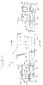
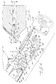
- the apparatus includes a main body 12 having a flow passageway 14, which provides for a main direction of flow indicated by arrows.
- the flow passageway includes in downstream order, a feed channel 16, a transverse flow-providing manifold 18 by which a flow stream is spread widthwise, a preland channel 20, and a land channel 22 that terminates in an exit slot 24 formed by lips 26,28.
- the manifold has a generally rectangular cross-section of substantially constant cross-sectional area from one end 30 to the other end 32.
- the manifold cross-section may be generally circular or tear drop-shaped.
- a support rod 38 Extending through an end plate 34 of main body 12 into manifold 18, and disposed generally parallel to the exit slot, is a support rod 38 to which an adjustable, upper deckle plug 40 is secured at an inner rod end 41.
- Upper plug 40 is disposed within the manifold and conveniently includes a fin portion 43 disposed within an upper portion 42 of preland channel 20.
- the upper plug has a concavely radiused face 44, and a trailing edge 46 that is also generally parallel to exit slot 24.
- deckle blade is meant for purposes of this description, a generally blade-shaped, deckle member disposed in the preland channel and having a transverse dimension substantially equal to or exceeding the maximum engagement of the member in the preland channel. Generally speaking, maximum engagement will be about 25% of the channel width.
- Deckle blade 50 beneficially terminates in an end 52 having an upstream edge 54 with a generally square corner and a trailing edge 56 that may be convexly radiused.
- the upstream edge is closely adjacent to trailing edge 46 of upper deckle plug 40, with clearance being provided to avoid frictional contact during adjustment.
- Concavely radiused face 44 of the upper plug and convexly radiused, trailing edge 56 of the blade end promote thinning of the edge flow under laminar flow conditions.
- an independently adjustable, deckle rod 60 is also extending through the end plate into the preland channel, and disposed generally parallel to the exit slot.
- rod 60 is positioned proximate to a transition wall 58 separating the preland channel from the land channel, and receives structural support from the transition wall, adjacent preland channel walls, and the trailing edge of deckle blade 50.
- the deckle rod is therefore closely adjacent to the trailing edge of the deckle blade; clearance is provided to avoid frictional contact during adjustment of either member.
- Deckle members 40,50,60 advantageously form a precise sliding fit in flow passageway 14. More particularly, deckle plug 40 is provided with a shape that is in precision sliding fit relationship with the manifold and an upper portion of the preland channel. The fit of the deckle blade is such that it presents a flat surface forming a complete closure of the respective channel portion except for the necessary mechanical clearance.
- Deckle blade 50 beneficially overcomes the deflection sensitivity and bending associated with the support rod for the independently adjustable, lower deckle portion of U.S. Patent 4,659,302 to Maejima. Furthermore, blade 50 advantageously reduces the volumetric area that may be filled by polymer which may leak behind the manifold and preland deckle plugs, and thus reduces stagnation and build up of such polymer. As a result, ease of adjustability of the deckle blade and downstream deckle rod 60 is maintained, and deleterious degradation of polymer and deposit thereof is reduced. Moreover, blade 50 prevents the flow pressure of polymer leaking behind upper plug 40, from adversely deflecting or bending deckle rod 60.
- an adjustment mechanism 62 for mechanically adjusting the extent of the deckle members within the flow passageway.
- the adjustment mechanism includes support shafts 64,66 each rigidly secured to main body 12 at one end, and securely connected at the other end to an irregularly-shaped, joining member 68.
- An inner end 70 of a rotatable shaft 72 is in threaded engagement with an internally threaded bore of support rod 38, and an outer end 74 extends through and is supported by joining member 68.
- a shaft-rotating device 76 conveniently in the form of a hand wheel, in connected to outer end 74 of the rotatable shaft. Rotation of the shaft may alternatively be provided by a pneumatically or electrically powered driving device.
- support rod 38 Connected to and extending above and below, support rod 38 is a generally vertically oriented member 78.
- An upper end 80 of member 78 terminates in a pointer that cooperates with a indicator scale 82 mounted on a sleeve 84 on support shaft 64, to indicate the relative positioning of the deckles.
- a stop member 85 is beneficially secured to member 78.
- a lower portion 86 of member 78 is fastened to and supports an outer portion 87 of the blade and an outer portion 88 of the deckle rod, located outside main body 12.
- blade portion 87 is slotted for connection with support member 78
- lower portion 86 of member 78 is provided with a slot through which outer deckle rod portion 88 extends.
- Tightening mechanisms 89,90 respectively lock the blade and deckle rod in place.
- deckle members 40,50 may be adjusted independently of each other and of member 60, as needed.
- Shaft-rotating device 76 may be used to provide simultaneous movement of the three deckles.
- a retainer member 91 and a sealing gasket 92 that cold forms under compression are beneficially employed.
- a sealing gasket of modified PTFE commercially available under the registered trademark GYLON from Garlock Inc., and in particular selected from the GYLON 3500 series, may be advantageously used.
- Other suitable cold-forming, gasket members may alternatively be employed.
- a sealing member 93 that is compressible and formable under heat and pressure, is advantageously disposed between an end 94 of the upper deckle plug and a backing member 95.
- Member 93 prevents leakage transversely past the upper deckle plug, and during adjustment, wipes the manifold free of and prevents deleterious build up of polymer.
- a sealing member 93 of similar composition to a GYLON sealing gasket may be used.
- the sealing gasket composition selected will depend upon the extrusion operating conditions; however, compressibility and creep relaxation values of less than about 50% will typically be desirable in this application.
- upper deckle plug 40A may extend through the end plate into the flow passageway.
- full width is meant for purposes of this description, a transverse dimension of an upper deckle plug substantially equal to or exceeding the maximum engagement of the plug in the transverse flow-providing manifold. Generally speaking, a maximum engagement length will be about 25% of the manifold width. Beneficially, this variation further reduces the void space into which polymer may leak with the build-up of deleterious deposits, and as a result, polymer drain holes may be omitted.
- deckle plug 40A a retainer and a sealing gasket similar to gasket 92, may be advantageously employed. Additionally, a flow passageway-sealing member similar to sealing gasket 93, may be used, and in this case, the upper deckle plug may be conveniently provided by two members, with the second member serving as the backing member.
- a preferred apparatus in accordance with a first aspect of the present invention includes an internal deckle system formed in downsteam order, by a deckle blade and a deckle rod that extend into the preland channel.
- the inventive apparatus overcomes the deflection sensitivity and bending associated with the support rod for the independently adjustable, lower deckle portion of U.S. Patent 4,659,302 to Maejima, reduces the available volumetric area in which polymer stagnation and build up may occur, and reduces deckle rod deflection.
- the modified, upper deckle plug of Figure 5 or 6 could be used with a separately adjustable, lower deckle plug and support rod as taught by U.S. Patent 4,659,302 to Maejima.
- a modified upper deckle plug in accordance with the present invention would reduce deflection of a lower deckle member otherwise caused by the flow pressure of leaking resin.
- the shaft rotating device is used to simultaneously move the three deckle members, with the pointer at end 80 of support member 78 indicating a selected set point on indicator scale 82. Thereafter, resin flow through apparatus 10 is begun. If desired or necessary, deckle plug 40 and deckle blade 50 may be further independently adjusted to reduce edge bead.
- Apparatus 110 of this embodiment lacks an upper deckle plug but otherwise corresponds in many respects to apparatus 10 as indicated by the use of corresponding numbers to designate like parts. For sake of brevity therefore, details previously described are not repeated.
- This embodiment may be selected for cast film extrusion, or for extruding a web of uniform thickness from a comparatively higher viscosity material than may be extruded by the apparatus of the first embodiment, which is better suited for the extrusion of relatively low viscosity materials.
- Suitability for cast film extrusion arises because cast film extrusion typically involves trimming away some of the web edge and recycling the trim, and thus beadless extrusion is not necessary. However, no edge bead may be formed in some applications of this embodiment.
- this embodiment may also be retrofit onto conventional coat-hanger type, extrusion dies.
- a manifold 118 within a main body 112 of apparatus 110 beneficially has a generally rectangular cross-section of diminishing cross-sectional area from a locus 117 of flow divergence to each of manifold ends 130,132, and has a rectilinear output edge 119.
- the manifold cross-section may be generally circular or tear drop-shaped.
- a pressure drop-compensating, preland channel 120 advantageously incrementally compensates for progressive decrease in flow pressure from locus 117 to each manifold end.
- the preland channel includes secondary and primary stages 121,123 formed by an undercut preland 125 and a preland 127, respectively, each of appropriate length in the main flow direction.
- the pressure drop-compensating preland could be that of a conventional coat-hanger type, extrusion apparatus.
- Apparatus 110 provides an internal deckle including an edge bead-reducing, deckle blade 150 and a width-controlling, deckle rod 160.
- the deckle blade beneficially terminates in a curved end 151 that is convex outwardly, and that may be considered to be generally tongue-shaped.
- a leading edge 154 and a trailing edge 156 of blade end 151 may be convexly radiused.
- a heating element 157 such as a cartridge heating element, which may be independently controllable. The purpose of this heating element is explained further below.
- the deckle rod is closely adjacent to the trailing edge of the blade. Clearance is, however, provided to avoid frictional contact between the deckle members when either is being adjusted.
- the deckle blade and deckle rod form a precise sliding fit in the preland channel.
- An adjustment mechanism 162 includes a rotatable shaft 172 having an enlarged inner end 170 secured in a retainer member 173 attached to main body 112. Axially movable along, and extending above and below, the rotatable shaft is a generally vertically oriented member 178 fitted with a sleeve 179 that provides an internally threaded bore for threaded contact with the rotatable shaft.
- FIG. 10 a variation of the embodiment of Figures 7 to 9 is shown. Corresponding numbers designate like parts.
- This variation generally corresponds to apparatus 110, except that an end 161 of the deckle rod may be beneficially provided with a flag-shaped member 163 that has a trailing edge 165 that advantageously extends downwardly to or near an exit slot 124, typically within about 1 to 3 mm of the exit slot.
- heating element 157 is beneficially employed, in order to maintain the retracted, functional end at substantially the same temperature as that of the polymer. It will therefore be understood that heating element 157, though not depicted, may likewise be beneficially employed in the first preferred embodiment of the present invention, as well as in the variations of the first and second preferred embodiments described herein.
- flag 163 beneficially prevents a web of inconsistent width, more particularly having a wavy or scalloped edge, from being formed. This edge problem is believed to result from a cavitation effect and inconsistent flow volume around the end of the furthest downstream, deckle member. It will be appreciated that this variation may likewise be applied to the first preferred embodiment of this invention.
- FIG. 12 and 13 a second variation of the embodiment of Figures 7 to 9 is shown.
- This variation generally corresponds to apparatus 110, except that the deckle rod is omitted, and a trailing edge 156 of a deckle blade 150 is disposed proximate to a transition wall 158 separating the preland and land channels. Also, as shown, a flag-shaped member 163 may be secured to the trailing edge of blade end 151. Corresponding numbers designate like parts.
- the leading edge of the deckle blade may be proximate to the leading edge of the preland channel.
- the deckle blade could have a length in the main flow direction that extends from the leading edge of the preland channel to transition wall 158.
Landscapes
- Engineering & Computer Science (AREA)
- Mechanical Engineering (AREA)
- Manufacturing & Machinery (AREA)
- Extrusion Moulding Of Plastics Or The Like (AREA)
Applications Claiming Priority (2)
| Application Number | Priority Date | Filing Date | Title |
|---|---|---|---|
| US915485 | 1986-10-06 | ||
| US91548592A | 1992-07-17 | 1992-07-17 |
Publications (2)
| Publication Number | Publication Date |
|---|---|
| EP0579142A1 true EP0579142A1 (fr) | 1994-01-19 |
| EP0579142B1 EP0579142B1 (fr) | 1997-11-19 |
Family
ID=25435831
Family Applications (1)
| Application Number | Title | Priority Date | Filing Date |
|---|---|---|---|
| EP93111087A Expired - Lifetime EP0579142B1 (fr) | 1992-07-17 | 1993-07-10 | Dispositif interne d'obtention de bords |
Country Status (4)
| Country | Link |
|---|---|
| US (2) | US5505609B1 (fr) |
| EP (1) | EP0579142B1 (fr) |
| JP (1) | JPH06166083A (fr) |
| DE (1) | DE69315268T2 (fr) |
Cited By (6)
| Publication number | Priority date | Publication date | Assignee | Title |
|---|---|---|---|---|
| AT724U1 (de) * | 1995-06-14 | 1996-04-25 | Engel Gmbh Maschbau | Düse mit einer düsenöffnung zum einbringen von geschmolzenem kunststoff |
| US5511962A (en) * | 1993-02-01 | 1996-04-30 | Extrusion Dies, Inc. | Extrusion die |
| DE19536893A1 (de) * | 1995-10-04 | 1997-04-10 | Er We Pa Davis Standard Gmbh | Breitschlitzdüse mit variabler Schlitzbreite |
| EP2865510A1 (fr) * | 2013-10-10 | 2015-04-29 | Nordson Corporation | Filière d'extrusion avec système d'étranglement et procédés d'utilisation associés |
| EP2830852A4 (fr) * | 2012-03-29 | 2015-12-02 | Cloeren Inc | Collecteur à zone de transition variable |
| EP4272926A1 (fr) * | 2022-05-03 | 2023-11-08 | LG Energy Solution, Ltd. | Appareil de détermination de décalage, système et procédé |
Families Citing this family (22)
| Publication number | Priority date | Publication date | Assignee | Title |
|---|---|---|---|---|
| WO1997009164A1 (fr) * | 1995-09-08 | 1997-03-13 | Crompton & Knowles Corporation | Systeme de reglage de largeur interne pour filiere d'extrusion de feuilles |
| DE29613687U1 (de) * | 1996-08-07 | 1996-10-24 | Voith Sulzer Papiermaschinen GmbH, 89522 Heidenheim | Auftragwerk zum direkten oder indirekten Auftragen eines flüssigen oder pastösen Streichmediums auf eine laufende Materialbahn, insbesondere aus Papier oder Karton |
| US6060636A (en) * | 1996-09-04 | 2000-05-09 | Kimberly-Clark Worldwide, Inc. | Treatment of materials to improve handling of viscoelastic fluids |
| DE19830728C2 (de) * | 1998-07-09 | 2001-08-02 | Reinhard Duespohl Maschb Gmbh | Kleber-Auftragsvorrichtung |
| US6245271B1 (en) | 1998-12-18 | 2001-06-12 | Kimberly-Clark Worldwide, Inc. | Reduced die lip buildup extrusion of polymer compositions |
| US6358449B1 (en) | 1999-11-22 | 2002-03-19 | Kimberly-Clark Worldwide, Inc. | Apparatus and method for reducing die accumulation |
| JP2002096370A (ja) * | 2000-09-26 | 2002-04-02 | Toray Ind Inc | 口金、シートならびにその製造装置および製造方法 |
| US7074030B2 (en) * | 2002-09-23 | 2006-07-11 | Extrusion Dies Industries, Llc. | Scraping assembly for an extrusion die and method of use therefor |
| DE10331325A1 (de) * | 2003-07-10 | 2005-02-03 | Voith Paper Patent Gmbh | Auftragsvorrichtung mit verstellbarer Auftragsbreite |
| EP1660299B1 (fr) | 2003-08-18 | 2010-06-23 | Flextrus Group AB | Filière d'extrusion avec systeme a etranglement interieur |
| US7104778B2 (en) * | 2004-03-16 | 2006-09-12 | Eastman Kodak Company | International die deckle with flow control |
| TWI399276B (zh) * | 2006-08-16 | 2013-06-21 | Fujifilm Corp | 流延裝置、溶液流延設備及溶液流延方法 |
| DE202006019724U1 (de) * | 2006-12-29 | 2007-03-01 | Nordson Corporation, Westlake | Vorrichtung mit Schlitzdüsenanordnung zum Abgeben von Fluid |
| US8092207B2 (en) * | 2007-05-03 | 2012-01-10 | Cloeren Incorporated | Decoupled transverse flow metering gap and lip gap |
| US8123511B2 (en) * | 2007-05-03 | 2012-02-28 | Cloeren Incorporated | Decoupled transverse flow metering gap and lip gap |
| EP2377623B1 (fr) * | 2010-04-13 | 2013-07-31 | Nordson Corporation | Dispositif d'application d'une matière liquide sur un substrat |
| JP5678545B2 (ja) * | 2010-09-28 | 2015-03-04 | 凸版印刷株式会社 | スロットダイ装置 |
| US8777605B2 (en) * | 2011-04-05 | 2014-07-15 | Nordson Extrusion Dies Industries, Llc | Deckle technology |
| US9149967B2 (en) * | 2011-11-16 | 2015-10-06 | Nordson Corporation | Extrusion dies with internal and/or external deckles |
| JP5766890B2 (ja) * | 2012-11-29 | 2015-08-19 | 株式会社カネカ | フィルムの製造方法、フィルム製造装置および治具 |
| US10040234B2 (en) | 2014-05-27 | 2018-08-07 | Nordson Corporation | Multi-manifold extrusion die with deckle system and method of using same |
| US11040366B2 (en) * | 2018-09-18 | 2021-06-22 | Canon Kabushiki Kaisha | Dispenser shield with adjustable aperture to improve drop placement and residual layer thickness |
Citations (6)
| Publication number | Priority date | Publication date | Assignee | Title |
|---|---|---|---|---|
| DE2202484A1 (de) * | 1971-01-21 | 1972-07-27 | Egan Machinery Co | Vorrichtung zur Randeinstellung an Spritzduesen zum Herstellen von Filmen oder Bahnen aus Kunststoff |
| US3832120A (en) * | 1972-10-19 | 1974-08-27 | Beloit Corp | Internal deckle structure |
| GB2092512A (en) * | 1981-02-05 | 1982-08-18 | Maejimi Mokichi | Extrusion die deckles |
| EP0084450A1 (fr) * | 1982-01-20 | 1983-07-27 | Ab Tetra Pak | Filière en T pour l'extrusion de pellicules thermoplastiques |
| US4454084A (en) * | 1982-06-09 | 1984-06-12 | Leesona Corporation | Extrusion die control system |
| US4659302A (en) * | 1985-01-22 | 1987-04-21 | Jyohoku Seiko Co., Ltd. | Deckle structure for a film extrusion die |
Family Cites Families (18)
| Publication number | Priority date | Publication date | Assignee | Title |
|---|---|---|---|---|
| US3018515A (en) * | 1957-12-23 | 1962-01-30 | Clyde Paper Company Ltd | Manufacture of plastic sheets |
| US3107191A (en) * | 1960-08-03 | 1963-10-15 | American Can Co | Method and apparatus for extruding plastic film |
| US3132377A (en) * | 1961-07-26 | 1964-05-12 | Blaw Knox Co | Deckle rod for an extrusion die |
| US3647346A (en) * | 1970-04-27 | 1972-03-07 | Monsanto Co | Extrusion die with adjustable dams |
| US3680997A (en) * | 1970-06-29 | 1972-08-01 | Pennwalt Corp | Extrusion strip die for thermoplastic sheet |
| US3706518A (en) * | 1971-06-17 | 1972-12-19 | Egan Machinery Co | Extrusion die deckle means |
| US3711235A (en) * | 1971-11-10 | 1973-01-16 | Egan Machinery Co | Extrusion die deckle means |
| US3840318A (en) * | 1972-09-20 | 1974-10-08 | Phillips Petroleum Co | Extruder with deckle bar having heating and cooling means |
| US3829274A (en) * | 1972-10-19 | 1974-08-13 | Beloit Corp | Interchangeable die lips for extrusion die and independently adjustable deckles therefor |
| US3870454A (en) * | 1973-02-01 | 1975-03-11 | Beloit Corp | Cooled deckle for die structure |
| US4057385A (en) * | 1974-06-29 | 1977-11-08 | Mitsubishi Petrochemical Co., Ltd. | Deckle cooling means to prevent leakage |
| US4248579A (en) * | 1979-10-10 | 1981-02-03 | Jyohoku Seiko Co., Ltd. | Film extrusion die |
| US4293517A (en) * | 1980-04-14 | 1981-10-06 | E. I. Du Pont De Nemours And Company | Die with insert and its use |
| JPS60165218A (ja) * | 1984-02-08 | 1985-08-28 | Johoku Seikosho:Kk | Tダイ |
| JPS61167523A (ja) * | 1985-01-22 | 1986-07-29 | Johoku Seikosho:Kk | Tダイ |
| JPH07106594B2 (ja) * | 1991-04-04 | 1995-11-15 | 株式会社江新エンジニアリング | 全幅埋込式ディッケルを備えた押出加工装置 |
| JPH0627614A (ja) * | 1992-07-10 | 1994-02-04 | Konica Corp | ハロゲン化銀写真感光材料 |
| JP3049950B2 (ja) * | 1992-07-10 | 2000-06-05 | 富士電機株式会社 | カップ式自動販売機 |
-
1993
- 1993-07-10 EP EP93111087A patent/EP0579142B1/fr not_active Expired - Lifetime
- 1993-07-10 DE DE69315268T patent/DE69315268T2/de not_active Expired - Fee Related
- 1993-07-16 JP JP5176887A patent/JPH06166083A/ja active Pending
-
1994
- 1994-10-31 US US08331912 patent/US5505609B1/en not_active Expired - Lifetime
-
1995
- 1995-06-05 US US08/465,602 patent/US5679387A/en not_active Expired - Lifetime
Patent Citations (6)
| Publication number | Priority date | Publication date | Assignee | Title |
|---|---|---|---|---|
| DE2202484A1 (de) * | 1971-01-21 | 1972-07-27 | Egan Machinery Co | Vorrichtung zur Randeinstellung an Spritzduesen zum Herstellen von Filmen oder Bahnen aus Kunststoff |
| US3832120A (en) * | 1972-10-19 | 1974-08-27 | Beloit Corp | Internal deckle structure |
| GB2092512A (en) * | 1981-02-05 | 1982-08-18 | Maejimi Mokichi | Extrusion die deckles |
| EP0084450A1 (fr) * | 1982-01-20 | 1983-07-27 | Ab Tetra Pak | Filière en T pour l'extrusion de pellicules thermoplastiques |
| US4454084A (en) * | 1982-06-09 | 1984-06-12 | Leesona Corporation | Extrusion die control system |
| US4659302A (en) * | 1985-01-22 | 1987-04-21 | Jyohoku Seiko Co., Ltd. | Deckle structure for a film extrusion die |
Non-Patent Citations (1)
| Title |
|---|
| DATABASE WPI Week 9012, Derwent Publications Ltd., London, GB; AN 90-086315 & JP-A-2 038 022 (TOMY KIKAI KOGYO KK) * |
Cited By (9)
| Publication number | Priority date | Publication date | Assignee | Title |
|---|---|---|---|---|
| US5511962A (en) * | 1993-02-01 | 1996-04-30 | Extrusion Dies, Inc. | Extrusion die |
| AT724U1 (de) * | 1995-06-14 | 1996-04-25 | Engel Gmbh Maschbau | Düse mit einer düsenöffnung zum einbringen von geschmolzenem kunststoff |
| DE19536893A1 (de) * | 1995-10-04 | 1997-04-10 | Er We Pa Davis Standard Gmbh | Breitschlitzdüse mit variabler Schlitzbreite |
| EP2830852A4 (fr) * | 2012-03-29 | 2015-12-02 | Cloeren Inc | Collecteur à zone de transition variable |
| EP2865510A1 (fr) * | 2013-10-10 | 2015-04-29 | Nordson Corporation | Filière d'extrusion avec système d'étranglement et procédés d'utilisation associés |
| CN104552870A (zh) * | 2013-10-10 | 2015-04-29 | 诺信公司 | 具有定边系统的挤出模具及其使用方法 |
| US9132580B2 (en) | 2013-10-10 | 2015-09-15 | Nordson Corporation | Extrusion die with deckle system and methods of using same |
| CN104552870B (zh) * | 2013-10-10 | 2018-09-11 | 诺信公司 | 具有定边系统的挤出模具及其使用方法 |
| EP4272926A1 (fr) * | 2022-05-03 | 2023-11-08 | LG Energy Solution, Ltd. | Appareil de détermination de décalage, système et procédé |
Also Published As
| Publication number | Publication date |
|---|---|
| DE69315268T2 (de) | 1998-05-28 |
| US5679387A (en) | 1997-10-21 |
| US5505609A (en) | 1996-04-09 |
| DE69315268D1 (de) | 1998-01-02 |
| EP0579142B1 (fr) | 1997-11-19 |
| JPH06166083A (ja) | 1994-06-14 |
| US5505609B1 (en) | 2000-01-18 |
Similar Documents
| Publication | Publication Date | Title |
|---|---|---|
| US5505609A (en) | Internal deckle system | |
| US3884611A (en) | Extrusion die | |
| US3856278A (en) | Twin-screw extruder with adjustable throttling means | |
| US2387718A (en) | Extrusion apparatus | |
| US3680997A (en) | Extrusion strip die for thermoplastic sheet | |
| JPS6367458B2 (fr) | ||
| US3241183A (en) | Film extrusion die | |
| US4217322A (en) | Process for extruding synthetic resin and die for use therein | |
| US20200368958A1 (en) | Screw extruder with rollers | |
| US4206876A (en) | Slot nozzle | |
| US4744745A (en) | Variable contour rubber extruder | |
| US5511962A (en) | Extrusion die | |
| EP0084450B1 (fr) | Filière en T pour l'extrusion de pellicules thermoplastiques | |
| US20200207002A1 (en) | Extrusion die with improved exit gap control | |
| US20020060030A1 (en) | Process for sealing pressure zones in a paper-making machine | |
| US3112525A (en) | Apparatus for extruding thermoplastic material | |
| EP1660299B1 (fr) | Filière d'extrusion avec systeme a etranglement interieur | |
| US2727275A (en) | Extrusion orifice end block | |
| US3132377A (en) | Deckle rod for an extrusion die | |
| RU2142361C1 (ru) | Головка экструдера с регулируемым профилем формующего канала | |
| JPH0661819B2 (ja) | Tダイ | |
| US20030080462A1 (en) | Extrusion die with horizontal and vertical extrudate opening adjustment | |
| US7131829B2 (en) | Spiral die assembly | |
| JPH03284926A (ja) | 熱可塑性樹脂フイルム・シートの押出方法 | |
| JP3660086B2 (ja) | ディッケル付tダイ |
Legal Events
| Date | Code | Title | Description |
|---|---|---|---|
| PUAI | Public reference made under article 153(3) epc to a published international application that has entered the european phase |
Free format text: ORIGINAL CODE: 0009012 |
|
| AK | Designated contracting states |
Kind code of ref document: A1 Designated state(s): BE DE GB IT |
|
| 17P | Request for examination filed |
Effective date: 19940716 |
|
| 17Q | First examination report despatched |
Effective date: 19950720 |
|
| GRAG | Despatch of communication of intention to grant |
Free format text: ORIGINAL CODE: EPIDOS AGRA |
|
| GRAH | Despatch of communication of intention to grant a patent |
Free format text: ORIGINAL CODE: EPIDOS IGRA |
|
| GRAH | Despatch of communication of intention to grant a patent |
Free format text: ORIGINAL CODE: EPIDOS IGRA |
|
| GRAA | (expected) grant |
Free format text: ORIGINAL CODE: 0009210 |
|
| AK | Designated contracting states |
Kind code of ref document: B1 Designated state(s): BE DE GB IT |
|
| REF | Corresponds to: |
Ref document number: 69315268 Country of ref document: DE Date of ref document: 19980102 |
|
| ITF | It: translation for a ep patent filed | ||
| PLBE | No opposition filed within time limit |
Free format text: ORIGINAL CODE: 0009261 |
|
| STAA | Information on the status of an ep patent application or granted ep patent |
Free format text: STATUS: NO OPPOSITION FILED WITHIN TIME LIMIT |
|
| 26N | No opposition filed | ||
| REG | Reference to a national code |
Ref country code: GB Ref legal event code: IF02 |
|
| PGFP | Annual fee paid to national office [announced via postgrant information from national office to epo] |
Ref country code: GB Payment date: 20030725 Year of fee payment: 11 |
|
| PG25 | Lapsed in a contracting state [announced via postgrant information from national office to epo] |
Ref country code: GB Free format text: LAPSE BECAUSE OF NON-PAYMENT OF DUE FEES Effective date: 20040710 |
|
| GBPC | Gb: european patent ceased through non-payment of renewal fee |
Effective date: 20040710 |
|
| PG25 | Lapsed in a contracting state [announced via postgrant information from national office to epo] |
Ref country code: IT Free format text: LAPSE BECAUSE OF NON-PAYMENT OF DUE FEES;WARNING: LAPSES OF ITALIAN PATENTS WITH EFFECTIVE DATE BEFORE 2007 MAY HAVE OCCURRED AT ANY TIME BEFORE 2007. THE CORRECT EFFECTIVE DATE MAY BE DIFFERENT FROM THE ONE RECORDED. Effective date: 20050710 |
|
| PGFP | Annual fee paid to national office [announced via postgrant information from national office to epo] |
Ref country code: DE Payment date: 20090708 Year of fee payment: 17 |
|
| PGFP | Annual fee paid to national office [announced via postgrant information from national office to epo] |
Ref country code: BE Payment date: 20090728 Year of fee payment: 17 |
|
| BERE | Be: lapsed |
Owner name: THE *CLOEREN CY Effective date: 20100731 |
|
| PG25 | Lapsed in a contracting state [announced via postgrant information from national office to epo] |
Ref country code: DE Free format text: LAPSE BECAUSE OF NON-PAYMENT OF DUE FEES Effective date: 20110201 |
|
| REG | Reference to a national code |
Ref country code: DE Ref legal event code: R119 Ref document number: 69315268 Country of ref document: DE Effective date: 20110201 |
|
| PG25 | Lapsed in a contracting state [announced via postgrant information from national office to epo] |
Ref country code: BE Free format text: LAPSE BECAUSE OF NON-PAYMENT OF DUE FEES Effective date: 20100731 |