EP0579271B1 - Verfahren zum Erfassen von Fehlzündungen in einer Brennkraftmaschine - Google Patents
Verfahren zum Erfassen von Fehlzündungen in einer Brennkraftmaschine Download PDFInfo
- Publication number
- EP0579271B1 EP0579271B1 EP93114333A EP93114333A EP0579271B1 EP 0579271 B1 EP0579271 B1 EP 0579271B1 EP 93114333 A EP93114333 A EP 93114333A EP 93114333 A EP93114333 A EP 93114333A EP 0579271 B1 EP0579271 B1 EP 0579271B1
- Authority
- EP
- European Patent Office
- Prior art keywords
- combustion
- nox
- engine
- misfire
- signal
- Prior art date
- Legal status (The legal status is an assumption and is not a legal conclusion. Google has not performed a legal analysis and makes no representation as to the accuracy of the status listed.)
- Expired - Lifetime
Links
Images


Classifications
-
- F—MECHANICAL ENGINEERING; LIGHTING; HEATING; WEAPONS; BLASTING
- F02—COMBUSTION ENGINES; HOT-GAS OR COMBUSTION-PRODUCT ENGINE PLANTS
- F02D—CONTROLLING COMBUSTION ENGINES
- F02D41/00—Electrical control of supply of combustible mixture or its constituents
- F02D41/02—Circuit arrangements for generating control signals
- F02D41/04—Introducing corrections for particular operating conditions
-
- F—MECHANICAL ENGINEERING; LIGHTING; HEATING; WEAPONS; BLASTING
- F02—COMBUSTION ENGINES; HOT-GAS OR COMBUSTION-PRODUCT ENGINE PLANTS
- F02D—CONTROLLING COMBUSTION ENGINES
- F02D35/00—Controlling engines, dependent on conditions exterior or interior to engines, not otherwise provided for
- F02D35/02—Controlling engines, dependent on conditions exterior or interior to engines, not otherwise provided for on interior conditions
- F02D35/022—Controlling engines, dependent on conditions exterior or interior to engines, not otherwise provided for on interior conditions using an optical sensor, e.g. in-cylinder light probe
-
- F—MECHANICAL ENGINEERING; LIGHTING; HEATING; WEAPONS; BLASTING
- F02—COMBUSTION ENGINES; HOT-GAS OR COMBUSTION-PRODUCT ENGINE PLANTS
- F02D—CONTROLLING COMBUSTION ENGINES
- F02D35/00—Controlling engines, dependent on conditions exterior or interior to engines, not otherwise provided for
- F02D35/02—Controlling engines, dependent on conditions exterior or interior to engines, not otherwise provided for on interior conditions
- F02D35/025—Controlling engines, dependent on conditions exterior or interior to engines, not otherwise provided for on interior conditions by determining temperatures inside the cylinder, e.g. combustion temperatures
-
- F—MECHANICAL ENGINEERING; LIGHTING; HEATING; WEAPONS; BLASTING
- F02—COMBUSTION ENGINES; HOT-GAS OR COMBUSTION-PRODUCT ENGINE PLANTS
- F02D—CONTROLLING COMBUSTION ENGINES
- F02D41/00—Electrical control of supply of combustible mixture or its constituents
- F02D41/02—Circuit arrangements for generating control signals
- F02D41/14—Introducing closed-loop corrections
- F02D41/1438—Introducing closed-loop corrections using means for determining characteristics of the combustion gases; Sensors therefor
- F02D41/1444—Introducing closed-loop corrections using means for determining characteristics of the combustion gases; Sensors therefor characterised by the characteristics of the combustion gases
- F02D41/1451—Introducing closed-loop corrections using means for determining characteristics of the combustion gases; Sensors therefor characterised by the characteristics of the combustion gases the sensor being an optical sensor
-
- F—MECHANICAL ENGINEERING; LIGHTING; HEATING; WEAPONS; BLASTING
- F02—COMBUSTION ENGINES; HOT-GAS OR COMBUSTION-PRODUCT ENGINE PLANTS
- F02P—IGNITION, OTHER THAN COMPRESSION IGNITION, FOR INTERNAL-COMBUSTION ENGINES; TESTING OF IGNITION TIMING IN COMPRESSION-IGNITION ENGINES
- F02P5/00—Advancing or retarding ignition; Control therefor
- F02P5/04—Advancing or retarding ignition; Control therefor automatically, as a function of the working conditions of the engine or vehicle or of the atmospheric conditions
- F02P5/045—Advancing or retarding ignition; Control therefor automatically, as a function of the working conditions of the engine or vehicle or of the atmospheric conditions combined with electronic control of other engine functions, e.g. fuel injection
-
- F—MECHANICAL ENGINEERING; LIGHTING; HEATING; WEAPONS; BLASTING
- F02—COMBUSTION ENGINES; HOT-GAS OR COMBUSTION-PRODUCT ENGINE PLANTS
- F02P—IGNITION, OTHER THAN COMPRESSION IGNITION, FOR INTERNAL-COMBUSTION ENGINES; TESTING OF IGNITION TIMING IN COMPRESSION-IGNITION ENGINES
- F02P5/00—Advancing or retarding ignition; Control therefor
- F02P5/04—Advancing or retarding ignition; Control therefor automatically, as a function of the working conditions of the engine or vehicle or of the atmospheric conditions
- F02P5/145—Advancing or retarding ignition; Control therefor automatically, as a function of the working conditions of the engine or vehicle or of the atmospheric conditions using electrical means
- F02P5/15—Digital data processing
- F02P5/152—Digital data processing dependent on pinking
-
- G—PHYSICS
- G01—MEASURING; TESTING
- G01M—TESTING STATIC OR DYNAMIC BALANCE OF MACHINES OR STRUCTURES; TESTING OF STRUCTURES OR APPARATUS, NOT OTHERWISE PROVIDED FOR
- G01M15/00—Testing of engines
- G01M15/04—Testing internal-combustion engines
- G01M15/042—Testing internal-combustion engines by monitoring a single specific parameter not covered by groups G01M15/06 - G01M15/12
- G01M15/048—Testing internal-combustion engines by monitoring a single specific parameter not covered by groups G01M15/06 - G01M15/12 by monitoring temperature
-
- G—PHYSICS
- G01—MEASURING; TESTING
- G01M—TESTING STATIC OR DYNAMIC BALANCE OF MACHINES OR STRUCTURES; TESTING OF STRUCTURES OR APPARATUS, NOT OTHERWISE PROVIDED FOR
- G01M15/00—Testing of engines
- G01M15/04—Testing internal-combustion engines
- G01M15/10—Testing internal-combustion engines by monitoring exhaust gases or combustion flame
- G01M15/102—Testing internal-combustion engines by monitoring exhaust gases or combustion flame by monitoring exhaust gases
- G01M15/108—Testing internal-combustion engines by monitoring exhaust gases or combustion flame by monitoring exhaust gases using optical methods
-
- Y—GENERAL TAGGING OF NEW TECHNOLOGICAL DEVELOPMENTS; GENERAL TAGGING OF CROSS-SECTIONAL TECHNOLOGIES SPANNING OVER SEVERAL SECTIONS OF THE IPC; TECHNICAL SUBJECTS COVERED BY FORMER USPC CROSS-REFERENCE ART COLLECTIONS [XRACs] AND DIGESTS
- Y02—TECHNOLOGIES OR APPLICATIONS FOR MITIGATION OR ADAPTATION AGAINST CLIMATE CHANGE
- Y02T—CLIMATE CHANGE MITIGATION TECHNOLOGIES RELATED TO TRANSPORTATION
- Y02T10/00—Road transport of goods or passengers
- Y02T10/10—Internal combustion engine [ICE] based vehicles
- Y02T10/40—Engine management systems
Definitions
- Patent Abstracts of Japan, Vol. 9, No. 135, June 11, 1985 and the Japanese Paten Application No. 58-123866 describe a combustion control device for an internal combustion engine.
- the known control device detects light emitted from the inside of the cylinder in an engine by means of a light detector. The detected light is converted in a signal of combustion temperature by a light-temperature converting means.
- a combustion control arithmetic means outputs a control signal of combustion on the basis of the output of a crank angle detecting means.
- a combustion control means controls the combustion temperature of the engine on the basis of the combustion control signal. In such way, the generation of NOx is suppressed while drivability of the engine and its fuel consumption are improved.
- the US-A-4 446 723 describes an ignition timing and mixture feedback control apparatus which uses a temperature sensor on the basis of a black body heat radiation detector for controlling the level of knock to a tolerable limit.
- the sensor includes an optical transmission element, a shaping circuit of generating an output correcting the ignition timing when the detected knock exceeds a predetermined limit.
- This known optical combustion event sensor detects the combustion gas temperature from an amount of heat released from a black body film joint to a tip of a light conductor integrated in an ignition plug.
- the US-A-4 446 723 does not describe to detect the combustion light at a specific wavelength of NOx light emission during the combustion fire.
- a temperature sensor or detector employing a black body which can directly detect temperature change in the combustion chamber, and which comprises a thin black body film and an optical transmission element connected to the black body film for transmitting radiant energy generated by the black body film.
- the misfire boundary and the NOx limit have characteristics shown in Fig. 4 with respect to air fuel ratio and ignition timing.
- the misfire boundary consists of the misfire boundary -A- on an advanced ignition timing side and the misfire boundary -B- on a delay ignition timing side.
- the NOx limit comes closer to the lean air fuel ratio side as the ignition timing advances.
- the NOx limit moves to the right-hand side in Fig. 4 and, hence, the target control range defined by the NOx limit and the misfire boundary becomes smaller, thereby making the control difficult.
- the misfire cycle includes a defective ignition cycle -B- in which a spark does not produce a flame nucleus, and a defective flame propagation cycle -A- in which ignition does not grow the flame. Both of these cycles are a cycle which produces little combustion flame light, so that it is possible to detect a misfire cycle from the intensity of the combustion light or the combustion temperature.
- NOx is a parameter of a combustion temperature. It is also said that the emission spectrum of NOx is a wavelength of 5.3 ⁇ m and the light intensity at this wavelength is a function of the concentration of NOx.
- a temperature detector using black body suitable to detect such a temperature is provided.
- the target control range must be on the left-hand side of the misfire boundary in Fig. 4, while if the NOx limit is taken into consideration, the target control range must be on the right-hand side of the NOx limit in Fig. 4. Therefore, if both are taken into consideration, the target control range must be set at the range surrounded by the misfire boundary and the NOx limit. Assuming that the misfire detector detects the misfiring state of the engine, and the A/F and Adv values at this state indicate point P 1 , the A/F is so controlled as to move in the direction of Rich and be situated at point P 2 , thereby cancelling the misfiring state. If the detected value of NOx is smaller than a tolerance limit of the NOx limit, it is judged to be controlled within the target control range.
- the A/F is made richer so as to reach the point P 9 , thereby escaping from the misfire boundary.
- the NOx is beyond the tolerance boundary at point P 9 , it is necessary to temporarily return to the point 8 so as to advance the ignition timing Adv by a predetermined value and simultaneously to make the A/F richer so as to reach point P 10 , thereby satisfying the conditions of both misfire and NOx.
- a control from P 9 to P 10 is possible, as described above.
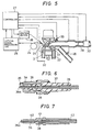
- Fig. 5 shows the total structure of the lean-burn control apparatus.
- a combustion sensor having a function of detecting the misfiring state of an engine and the concentration of NOx comprises a combustion detecting terminal 21 mounted on a combustion chamber 23 of the engine 22 in such a manner as to communicate with the combustion chamber 23, an optical fiber cable for carrying out optical transmission between the combustion detecting terminal 21 and an optical signal processing circuit 25, and the optical signal processing circuit 25.
- the combustion detecting terminal 21 may be either integrally provided with an ignition plug, as shown in Fig. 6, or of a stand-alone type, as shown in Fig. 7.
- the former type of detection terminal is mounted on the apparatus.
- an ignition pulse is provided for the combustion detecting terminal 21 by a controller 27 having a built-in microcomputer through an ignition device 26, so that the combustion detecting terminal also has a function of an ignition plug.
- a combustion light signal or combustion temperature signal which is subjected to photoelectric conversion and signal processing by the optical signal processing circuit 25 is introduced to the controller 27.
- an air fuel ratio signal detected by an air fuel ratio sensor 28 or oxygen sensor
- a throttle valve opening degree information signal supplied from a throttle valve opening degree sensor or a throttle valve opening degree switch 29 is also inputted.
- the multi-point fuel injection system is adopted, but the present invention is not restricted thereto, and any system such as a carburetor and a sigle-point fuel injection system may be adopted.
- any other air flow rate measuring system may be adopted such as a speed density system for calculating the air flow rate from the revolution number of the engine and the suction negative pressure and a system for calculating the air flow rate from the revolution number of the engine and the opening degree of the throttle valve.
- a method of detecting misfire it is generally inferred from the change of the rotational speed of the engine.
- a method of detecting misfire from the intensity of the combustion flame light or the combustion temperature at the time of combustion is adopted.
- the concentration of NOx is obtained from the combustion temperature by utilizing the fact that there is a corresponding relationship between the combustion temperature in the combustion chamber and the concentration of NOx.
- a method of obtaining the concentration of NOx from the intensity of the combustion light at the wavelength of 5.3 ⁇ m is adopted by utilizing the fact that the emission spectrum of NOx is 5.3 ⁇ m.
- a method of inferring the concentration of NOx from the temperature of the exhaust gas immediately after the combustion chamber is effective, because the temperature of this exhaust gas substantially corresponds to the combustion temperature.
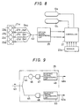
- Fig. 8 schematically shows the structure of the transmission and processing of an optical signal according to an embodiment of the invention.
- the combustion light detecting terminal 21 is mounted on each of the combustion chambers 23a to 23d in a manner as shown in Fig. 5.
- the present invention also allows a system for detecting only one specified chamber.
- the optical signals from the combustion light detecting terminals 21a, 21b, 21c and 21d are introduced to the optical signal processing circuit 25 through the respective optical fiber cables 24a, 24b, 24c and 24d.
- As the optical fiber cable 24 a high heat-resistant plastic fiber which can resist a temperature above about 140 to 150°C is preferable.
- a plastic fiber facilitates the formation of an integrated single-core fiber 43 which is composed by melting the plural fibers into one fiber, as shown in Fig. 8.
- the misfire signal and the NOx signal obtained in this way are introduced to the controller 27, as shown in Fig. 8, and computed together with a plurality of other engine parameter signals 22a, whereby the air fuel ratio control 13a and the ignition timing control 12a are effected.
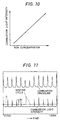
- Fig. 10 shows a relationship between the concentration of NOx and the combustion light intensity signal in the 5.3 ⁇ m zone in the case of adopting the system shown in Figs. 8 and 9. Since they have substantially proportional relationship, an electric signal output from the signal output end 49a in Fig. 9 takes the value substantially corresponding to the concentration of NOx.
- the engine is judged to be in a misfiring state, and signal pulse corresponing to this misfire cycle is produced and transmitted to the controller 27.
- the misfire information is consecutively transmitted to the controller.
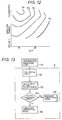
- Fig. 12 shows the average value of the peak values V p for several cycles of the combustion light intensity signals shown in Fig. 11 with respect to the air fuel ratio and the ignition timing represented by a contour line.
- the contour line of V p has a configuration well corresponding to the curve of the misfire boundary in Fig. 4, and judgement as to misfire also may be made by using the average value V p for several cycles.
- Fig. 13 is a flow chart for judging the tolerance limit of NOx.
- the signal is photoelectrically converted into an electric signal through the photoelectric transducer 47 and the electric signal processing circuit 49 shown in Fig. 9, and the electric signal input as a NOx signal to the controller 27 at step 52.
- the concentration of NOx is calculated at the step 53 according to the characteristics shown in Fig. 10. In this case, it is preferable to obtain the average value for several ten power cycles.
- the tolerance value (value satisfying the right-hand side range of the NOx limit line of Fig. 4) is compared with the NOx value calculated at the step 53 and judgement is made as to whether or not the calculated NOx value is in the range of the tolerance limit. If the answer is yes, the process proceeds to step 55 for the ordinary operational mode, while if the answer is no, the process proceeds to step 56 for the collecting operational mode and various controls are executed.
- Fig. 14 is a flow chart for judging a misfiring state.
- the combustion light intensity signal is photoelectrically converted through the photoelectric transducer 48 and the electric signal processing circuit 50 in Fig. 9 at step 57 and a misfire pulse is produced at the electric signal processing circuit 50 at step 58.
- the waveform of the combustion light intensity signal as shown in Fig. 11 is input at the step 58, and judgement is made as to whether the peak value of the waveform of the combustion light intensity signal produced in each power cycle is larger or smaller than a predetermined slicing level S as shown in Fig. 11. If the peak value is larger than S, the cycle is judged to be misfire, and a misfire pulse is produced and outputted for a predetermined period in the corresponding cycle.
- the misfire pulses obtained in this way are inputted to the controller 27 at step 59.
- the misfire pulses produced at the step 59 are counted for a predetermined number of times of power cycles at the step 60 and the count value is supplied to step 61.
- step 61 whether or not the count value is above a predetermined value is judged, and if the answer is yes, the process proceeds to the correcting operational mode 62, while if the answer is no, the process proceeds to the ordinary operational mode 63.
- the portion A in Fig. 13 and the portion A' in Fig. 14 are executed by the controller 27.
- the signals of the engine revolution number N E and the air flow rate Q A are inputted to the controller 27 and further at step 65, signals of air fuel ratio A/F (the value is represented by X) and ignition timing Adv (the value is represented by Y) are inputted to the controller 27.
- the signal of the misfire pulses (M) produced at the electric signal processing circuit 50 in Fig. 9 and the signal of NOx (N) produced at the electric signal processing circuit 49 are inputted to the controller 27.
- the value of N is a waveform peak-held for each power cycle.
- the concentration of NOx is converted from the NOx signal (N) inputted at the step 66 by using the characteristics shown in Fig. 10.
- the thus-converted concentration values of NOx for given several ten power cycles are averaged to calculated the average value N ⁇ .
- the processing is executed only when the NOx is out of the tolerance limit and misfire is within the tolerance limit.
- the operation is carried out in the case where the signals are situated at the points such as P 3 , P 5 and P 9 in Fig. 4.
- the amount of air or fuel is controlled by this control signal, and the mixture having a leaner air fuel ratio than that at the previous time is supplied to the engine.
- controller 27 It is effective to add the controller 27 a function of storing A/F and Adv in a map table made from the N E and the Q A when A/F and Adv are moved to the target control range in this way and renewing these values when new A/F and Adv are obtained by executing similar control at the preceding cycle. It is also effective to obtain the misfire boundary line and NOx limit line by the repetition of the above-described controls and store these lines on the map table of A/F and Adv.
- Figs. 16 to 18 show in example of a detector 110 suitable for detecting combustion temperature which can be used for the combustion detecting terminal 21 used in the system shown in Fig. 5.
- the detector 110 comprises an end portion of an optical transmission element 111 made of quartz (or fused silica fiber) having a diameter of about 1 mm and having a resistance to a temperature of 300 to 1,500°C in the combustion chamber 23, and a thin black body film 112 of iridium having a linear expansion coefficient approximate to that of quartz and attached to the end portion of the optical transmission element 111.
- the end portion of the element 111 is obliquely cut to provide a large end surface for detecting spectral radiant energy.
- the black body film 112 is attached to the end so as to cover the end portion of the element including the cut surface.
- the black body film 112 is covered with a protective film 113 made of high heat-resistant material such as quartz and ceramic to prevent the black body film from being peeled from the element 111 and to prevent the deterioration of the black body film 112 due to oxidization and corrosion.
- a protective film 113 made of high heat-resistant material such as quartz and ceramic to prevent the black body film from being peeled from the element 111 and to prevent the deterioration of the black body film 112 due to oxidization and corrosion.
- the black body film 112 is formed on the end portion of the element 111 by evaporation, sputtering or the like.
- the protective film 113 is also formed on the surface of the element 111 by evaporation, sputtering or the like.
- the protective film 113 is fused to the element 111 at an end thereof, so that it is firmly adhered to the element 111.
- a sapphire rod may be used in place of the element 111.
- the black body film 112 and the protective film 113 preferably have a thickness of as small as about 2 to 5 ⁇ m from the point of view of heat capacity. However, when a sufficient adhesion is not obtained, the thickness of those films is increased.
- the detector 110 including a part of the optical transmission elements 111, it is also possible to use platinum, zirconium nitride or graphite as the black body 112, and, if measurement of a high temperature is necessary, to use sapphire as the optical transmission element.
- the detector 110 and part of the optical transmission element 111 is located in the combustion chamber 23 of an engine and secured to a wall portion 22a of the combustion chamber 23 by screwing.
- a metal pipe 114 is secured to the outer periphery of the optical transmission element 111 by a fused glass 115 and the outer periphery of the metal pipe 114 is threaded.
- a thread bore engaging the metal pipe 114 is formed on the wall 22a of the combustion chamber 23. The detector 110 and the optical transmission element 111 is screwed into and fixed on the wall 22a through the metal pipe 114.
- Another example of the detector is of a plug type as shown in Fig. 19.
- the detector portion 36b is an end of fused silica or quartz fiber 36 which is disposed in a central electrode 34.
- the other construction including a high voltage terminal 35, electrically insulating porcelain 37, a sealing 38 and a grounding electrode is the same as in Fig. 6.
- a black body produces radiant energy to a temperature.
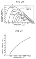
- Fig. 20 shows a relationship between the spectral radiant energy and wavelength and temperature of a black body. It is possible to infer the temperature by detecting the radiant energy with respect to a certain wavelength. For example, the temperature of 1,000 to 5,000°C is obtained by detecting the radiant energy at the wavelength of a point P in Fig. 20.
- Fig. 21 shows the characteristics of optical current with respect to the combustion temperature of a photoelectric transducer.
- the optical current changes on a log scale with respect to a change in temperature. Therefore, in the case of detection in a wide temperature range, a technique of logarithmically compressing the optical current through a log diode for linearization or the like is added.
- Fig. 22 shows a relationship between combustion temperature and NOx.
- concentration of NOx there is little difference in the concentration of NOx between 1 atm and 50 atm in the pressure in the combustion chamber and it is understood that the influence of the pressure is negligible in an ordinary combustion state. Therefore, if the air fuel ratio is detected at a specified time, the concentration of NOx is easily calculated from the combustion temperature at that time. Since the value corresponding to the average air fuel ratio is detected by the air fuel ratio sensor 28, as shown in Fig. 5, if the combustion temperature is detected, it is possible to calculate the concentration of NOx.
- Fig. 23 shows the structure of the signal processing circuit 25 in the case of adopting the combustion temperature detecting system.
- the heat radiating light from the black body film 112 at the end portion 110 or 36b introduced by the single-core integrated fiber 43 is introduced to a photoelectric transducer 90 through an optical filter 89 which transmits only light of a specific wavelength (e.g., 700 nm). Since the intensity of the radiating light is a function of a temperature, information on the combustion temperature is obtained by photoelectric convention of the light intensity. In case of a misfire cycle, the combustion temperature naturally does not rise.
- a specific wavelength e.g. 700 nm
- the electric signal processing circuit 91 forms the waveforms of the combustion temperature signals for the respective cycles which are substantially equal to the waveforms of the combustion temperature signals shown in Fig. 11 by utilizing the characteristics shown in Figs. 20 and 21.
- a given slicing level is set by utilizing the fact that the combustion temperature does not rise at the time of misfire, and when the combustion temperature signal in a power cycle does not exceed the slicing level, one misfire pulse is produced in that power cycle and the signal is output from an output end 92. From an output end 93, the peak value of the combustion signal which is peak held at each power cycle is output.
- Fig. 24 is a flow chart for judging the tolerance limit of NOx.
- the signal photoelectrically converted by the photoelectric transducer 90 and peak held at each power cycle by the electric signal processing circuit 91 in Fig. 23 (at step 94) is transmitted to the controller 27 and inputted as a combustion temperature signal at step 95.
- Fig. 25 is a flow chart for judging a misfiring state.
- the misfire pulse obtained by photoelectrically converting a signal by the photoelectric transducer 90 (at the step 94) and produced by the electric signal processing circuit 91 (at the step 103) in Fig. 23 is transmitted to the controller 27 and inputted as a misfire pulse at step 104.
- the number of the misfire pulses is counted for a predetermined power cycles, and judgment is made as to whether or not the value is above a preset value. If the value is less than the preset value, the combustion state is judged to be a non-misfiring state, and the process proceeds to the step 101.
- the state is judged to be a misfiring state, and the process proceeds to the step 102, and the same control as that in Fig. 24 and the portion B' in Fig. 25 are carried out by the controller 27.
- An engine control system employing the above-mentioned temperature detector such as the detector disclosed in Figs. 16 to 19 is capable of a precise and effective control of an internal combustion engine because the sensor directly detects the temperature in the combustion chamber of the engine.
Landscapes
- Engineering & Computer Science (AREA)
- Chemical & Material Sciences (AREA)
- Combustion & Propulsion (AREA)
- Mechanical Engineering (AREA)
- General Engineering & Computer Science (AREA)
- Physics & Mathematics (AREA)
- General Physics & Mathematics (AREA)
- Signal Processing (AREA)
- Combined Controls Of Internal Combustion Engines (AREA)
- Ignition Installations For Internal Combustion Engines (AREA)
Claims (5)
- Verfahren zum Erfassen von Fehlzündungen in einer Brennkraftmaschine mit den Schritten:.- Erfassen der Verbrennungslichtintensität, die eine Funktion der Verbrennungstemperatur in entsprechenden Brennkammern (23a-d) des Motors ist,- Umwandeln der Verbrennungslichtintensität in elektrische Signale (50a) durch einen photoelektrischen Wandler (48),- Bestimmen einer Fehlzündung des Motors wenn ein Durchschnittssignalniveau (Vp) der elektrischen Signale für eine vorbestimmte Anzahl von Leistungszyklen des Motors unterhalb eines vorbestimmten Schnittniveaus (S) liegt, das unter Verwendung der Tatsache eingestellt wird, daß die Verbrennungstemperatur nicht während einer Fehlzündung ansteigt, und- Korrigieren des Luft/Kraftstoff-Verhältnisses und des Zündzeitpunkts des Motors gemäß der erfaßten Fehlzündung.
- Verfahren zum Erfassen von Fehlzündungen nach Anspruch 1, wobei die Verbrennungstemperatur unter Verwendung eines schwarzen Körpers (112) erfaßt wird, der in dem Motor angeordnet ist.
- Verfahren zum Erfassen von Fehlzündungen nach Anspruch 2, wobei Hitzestrahlungslicht von dem schwarzen Körper, das der Verbrennungstemperatur entspricht, über ein optisches Filter (89) zu einem photoelektrischen Wandler (90) übertragen wird.
- Verfahren zum Erfassen von Fehlzündungen nach Anspruch 3, wobei das optische Filter nur spezifische Wellenlängen überträgt.
- Verfahren zum Erfassen von Fehlzündungen nach Anspruch 4, wobei die spezifische Wellenlänge 700 nm beträgt.
Applications Claiming Priority (5)
| Application Number | Priority Date | Filing Date | Title |
|---|---|---|---|
| JP96123/87 | 1987-04-21 | ||
| JP62096123A JPH0759934B2 (ja) | 1987-04-21 | 1987-04-21 | ノツク制御装置 |
| JP138071/87 | 1987-06-03 | ||
| JP62138071A JPH0794808B2 (ja) | 1987-06-03 | 1987-06-03 | リーンバーンエンジン制御装置及び制御方法 |
| EP90118320A EP0412578B1 (de) | 1987-04-21 | 1988-04-21 | Gerät und Methode zur Steuerung der Verbrennung für einen Verbrennungsmotor |
Related Parent Applications (3)
| Application Number | Title | Priority Date | Filing Date |
|---|---|---|---|
| EP90118320A Division-Into EP0412578B1 (de) | 1987-04-21 | 1988-04-21 | Gerät und Methode zur Steuerung der Verbrennung für einen Verbrennungsmotor |
| EP90118320A Division EP0412578B1 (de) | 1987-04-21 | 1988-04-21 | Gerät und Methode zur Steuerung der Verbrennung für einen Verbrennungsmotor |
| EP90118320.2 Division | 1990-09-24 |
Publications (2)
| Publication Number | Publication Date |
|---|---|
| EP0579271A1 EP0579271A1 (de) | 1994-01-19 |
| EP0579271B1 true EP0579271B1 (de) | 1997-03-26 |
Family
ID=26437352
Family Applications (3)
| Application Number | Title | Priority Date | Filing Date |
|---|---|---|---|
| EP90118320A Expired - Lifetime EP0412578B1 (de) | 1987-04-21 | 1988-04-21 | Gerät und Methode zur Steuerung der Verbrennung für einen Verbrennungsmotor |
| EP93114333A Expired - Lifetime EP0579271B1 (de) | 1987-04-21 | 1988-04-21 | Verfahren zum Erfassen von Fehlzündungen in einer Brennkraftmaschine |
| EP88106402A Expired - Lifetime EP0288056B1 (de) | 1987-04-21 | 1988-04-21 | Steuervorrichtung für Motoren mit innerer Verbrennung |
Family Applications Before (1)
| Application Number | Title | Priority Date | Filing Date |
|---|---|---|---|
| EP90118320A Expired - Lifetime EP0412578B1 (de) | 1987-04-21 | 1988-04-21 | Gerät und Methode zur Steuerung der Verbrennung für einen Verbrennungsmotor |
Family Applications After (1)
| Application Number | Title | Priority Date | Filing Date |
|---|---|---|---|
| EP88106402A Expired - Lifetime EP0288056B1 (de) | 1987-04-21 | 1988-04-21 | Steuervorrichtung für Motoren mit innerer Verbrennung |
Country Status (4)
| Country | Link |
|---|---|
| US (2) | US4887574A (de) |
| EP (3) | EP0412578B1 (de) |
| KR (1) | KR930000346B1 (de) |
| DE (3) | DE3855849T2 (de) |
Families Citing this family (54)
| Publication number | Priority date | Publication date | Assignee | Title |
|---|---|---|---|---|
| DE3829797A1 (de) * | 1988-09-02 | 1990-03-15 | Bosch Gmbh Robert | Elektronische motorsteuerung mit funktionspruefung fuer die zuendungsendstufe |
| KR930009907B1 (ko) * | 1988-10-04 | 1993-10-13 | 미쯔비시 덴끼 가부시끼가이샤 | 내연기관 제어장치 |
| GB9002935D0 (en) * | 1990-02-09 | 1990-04-04 | Lucas Ind Plc | Misfire detection |
| US5067463A (en) * | 1990-02-26 | 1991-11-26 | Barrack Technology Limited | Method and apparatus for operating an engine |
| US5099683A (en) * | 1990-05-22 | 1992-03-31 | Barrack Technology Limited | Method and apparatus for determining certain operating and running parameters in an internal combustion engine |
| AU7464991A (en) * | 1990-02-26 | 1991-09-18 | Barrack Technology Limited | Engine condition determining and operating method |
| US5103789A (en) * | 1990-04-11 | 1992-04-14 | Barrack Technology Limited | Method and apparatus for measuring and controlling combustion phasing in an internal combustion engine |
| US5038744A (en) * | 1990-06-21 | 1991-08-13 | Barrack Technology Limited | Method and apparatus for controlling spark ignition in an internal combustion engine |
| US5219227A (en) * | 1990-08-13 | 1993-06-15 | Barrack Technology Limited | Method and apparatus for determining burned gas temperature, trapped mass and NOx emissions in an internal combustion engine |
| FR2667113B1 (fr) * | 1990-09-26 | 1993-06-25 | Semt Pielstick | Procede de surveillance de l'emission d'oxydes d'azote par un moteur a combustion interne. |
| JPH04262039A (ja) * | 1991-02-18 | 1992-09-17 | Mitsubishi Electric Corp | 内燃機関の失火検出装置 |
| US5373448A (en) * | 1991-04-24 | 1994-12-13 | Hitachi, Ltd. | Knock detection device for an internal combustion engine |
| US5164999A (en) * | 1991-05-20 | 1992-11-17 | Johnson Matthey, Inc. | Blackbody fired on silica fiber |
| US5257496A (en) * | 1992-05-05 | 1993-11-02 | General Electric Company | Combustion control for producing low NOx emissions through use of flame spectroscopy |
| US5285676A (en) * | 1992-08-03 | 1994-02-15 | Motorola, Inc. | Air-fuel ratio measurement apparatus and method therefor |
| DK0632864T3 (da) * | 1993-01-28 | 1998-02-16 | Jenbacher Energiesysteme Ag | Indretning til bestemmelse af motorparametre for en forbrændingsmotor |
| US6456927B1 (en) * | 1993-03-22 | 2002-09-24 | Motorola, Inc. | Spectral knock detection method and system therefor |
| JP2807736B2 (ja) * | 1993-08-19 | 1998-10-08 | 本田技研工業株式会社 | 内燃機関の燃焼状態判定装置 |
| JP2807737B2 (ja) * | 1993-09-10 | 1998-10-08 | 本田技研工業株式会社 | 内燃エンジンの燃焼状態検出装置 |
| DE4444972C2 (de) * | 1993-12-17 | 2000-08-31 | Fuji Heavy Ind Ltd | Elektronisches Steuerverfahren und Steuersystem für einen Motor |
| DE4447858C2 (de) * | 1993-12-17 | 2002-09-26 | Fuji Heavy Ind Ltd | Elektronisches Steuersystem und Steuerverfahren für einen Motor |
| DE4402938A1 (de) * | 1994-02-01 | 1995-08-03 | Fev Motorentech Gmbh & Co Kg | Verfahren zur Steuerung eines Kolbenverbrennungsmotors unter Einhaltung der Laufgrenze |
| SE508563C2 (sv) * | 1994-02-22 | 1998-10-12 | Scania Cv Ab | Sensor för detektering av joniseringsgrad i en förbränningsmotors förbränningsrum jämte förbränningsmotor försedd med joniseringssensor |
| US5467185A (en) * | 1994-07-15 | 1995-11-14 | General Electric Company | Emissions control for internal combustion engine |
| US5763888A (en) * | 1995-01-30 | 1998-06-09 | Ametek Aerospace Products, Inc. | High temperature gas stream optical flame sensor and method for fabricating same |
| GB2301898B (en) * | 1995-06-07 | 1999-09-01 | Cummins Engine Co Inc | A system and method for detecting engine cylinder misfire |
| US6243641B1 (en) | 1995-06-07 | 2001-06-05 | Cummins Engine Company, Inc. | System and method for detecting engine cylinder misfire |
| US5553575A (en) * | 1995-06-16 | 1996-09-10 | Servojet Products International | Lambda control by skip fire of unthrottled gas fueled engines |
| JP3268517B2 (ja) * | 1995-07-28 | 2002-03-25 | 株式会社ユニシアジェックス | 内燃機関における燃焼改善機構の診断装置 |
| US5700954A (en) * | 1996-10-31 | 1997-12-23 | Ford Global Technologies, Inc. | Method of controlling fuel during engine misfire |
| US5961314A (en) * | 1997-05-06 | 1999-10-05 | Rosemount Aerospace Inc. | Apparatus for detecting flame conditions in combustion systems |
| US5983866A (en) * | 1997-10-27 | 1999-11-16 | Caterpillar Inc. | Diagnostic apparatus and method for a combustion sensor feedback system |
| US6931836B2 (en) * | 1997-12-12 | 2005-08-23 | Man Nutzfahrzeuge Ag | Method for NOx reduction of externally-ignited, explosion, internal combustion engines |
| DE19755299A1 (de) * | 1997-12-12 | 1999-06-17 | Man Nutzfahrzeuge Ag | Verfahren zur NO¶x¶-Reduzierung an gemischverdichtenden Brennkraftmaschinen |
| US6363778B1 (en) * | 1998-12-17 | 2002-04-02 | Honeywell International Inc. | Engine misfire monitor |
| US7112796B2 (en) * | 1999-02-08 | 2006-09-26 | General Electric Company | System and method for optical monitoring of a combustion flame |
| JP2000240550A (ja) * | 1999-02-18 | 2000-09-05 | Mitsubishi Electric Corp | 内燃機関の失火検出装置 |
| DE10105366A1 (de) * | 2001-02-06 | 2002-08-29 | Siemens Ag | Elektrische Verbindungsstruktur im Kraftfahrzeug |
| DE10107595A1 (de) | 2001-02-17 | 2002-08-29 | Bayerische Motoren Werke Ag | Elektromagnetischer Ventiltrieb |
| AT5153U1 (de) * | 2001-03-22 | 2002-03-25 | Avl List Gmbh | Optischer sensor zur erfassung von verbrennungsvorgängen |
| DE10316112A1 (de) * | 2003-04-09 | 2004-10-28 | Daimlerchrysler Ag | Verfahren zum Betrieb einer Brennkraftmaschine mit Selbstzündung |
| DE10332517A1 (de) * | 2003-07-17 | 2005-02-03 | Robert Bosch Gmbh | Verfahren und Vorrichtung zum Betreiben einer Brennkraftmaschine |
| US8469700B2 (en) | 2005-09-29 | 2013-06-25 | Rosemount Inc. | Fouling and corrosion detector for burner tips in fired equipment |
| ITBO20050789A1 (it) | 2005-12-23 | 2007-06-24 | Ferrari Spa | Metodo per il controllo dell'anticipo di accensione in un motore a combustione interna. |
| FR2899686B1 (fr) * | 2006-04-07 | 2008-06-06 | Ecoles Des Mines De Nantes | Procede et dispositif de detection d'une phase de fonctionnement perturbee d'un moteur a allumage commande se traduisant par le phenomene de cliquetis |
| US20080104944A1 (en) * | 2006-10-31 | 2008-05-08 | Caterpillar Inc. | Engine emissions control system |
| AT503276B1 (de) | 2007-05-31 | 2010-06-15 | Avl List Gmbh | Verfahren zur bewertung des zustandes eines kraftstoff/luft-gemisches |
| US8265851B2 (en) * | 2009-05-18 | 2012-09-11 | Closed-Loop Engine Technology, Llc | Method of controlling engine performance |
| US9279406B2 (en) | 2012-06-22 | 2016-03-08 | Illinois Tool Works, Inc. | System and method for analyzing carbon build up in an engine |
| JP6088397B2 (ja) * | 2013-10-15 | 2017-03-01 | 日本特殊陶業株式会社 | 点火時期制御装置および点火時期制御システム |
| AT517272B1 (de) * | 2015-06-03 | 2017-03-15 | Ge Jenbacher Gmbh & Co Og | Verfahren zum Betreiben einer Brennkraftmaschine |
| WO2017116490A1 (en) | 2015-12-30 | 2017-07-06 | Cummins Inc. | Control strategies for lean burn spark ignition engines |
| US10544726B2 (en) * | 2017-11-06 | 2020-01-28 | Ford Global Technologies, Llc | Methods and systems for a fuel injector |
| GB2597965B (en) * | 2020-08-12 | 2022-11-23 | Caterpillar Energy Solutions Gmbh | Misfire classification method and control unit for an internal combustion engine |
Citations (1)
| Publication number | Priority date | Publication date | Assignee | Title |
|---|---|---|---|---|
| US4446723A (en) * | 1981-03-20 | 1984-05-08 | Robert Bosch Gmbh | Optical combustion event sensor structure particularly knock sensor for an internal combustion engine |
Family Cites Families (14)
| Publication number | Priority date | Publication date | Assignee | Title |
|---|---|---|---|---|
| US3067610A (en) * | 1958-10-02 | 1962-12-11 | Gen Motors Corp | Gated amplitude indicator |
| GB1483612A (en) * | 1974-07-05 | 1977-08-24 | Lumenition Ltd | Detection of combustion in internal combustion engines |
| DE3111135A1 (de) * | 1980-06-20 | 1982-03-11 | Robert Bosch Gmbh, 7000 Stuttgart | Verfahren zum regeln der verbrennung in den brennraeumen einer brennkraftmaschine |
| DE3108460A1 (de) * | 1981-02-13 | 1982-11-04 | Pischinger, Franz, Prof. Dipl.-Ing. Dr.Techn., 5100 Aachen | Verfahren zum erkennen klopfender verbrennung sowie vorrichtung zur durchfuehrung des verfahrens |
| US4437334A (en) * | 1981-02-13 | 1984-03-20 | Franz Pischinger | Method and apparatus for detecting knocking combustion |
| JPS57186040A (en) * | 1981-05-13 | 1982-11-16 | Hitachi Ltd | Air-fuel ratio feedback controller |
| JPS5813137A (ja) * | 1981-07-18 | 1983-01-25 | Yoshiyuki Morita | 内燃機関の制御装置 |
| EP0071557B1 (de) * | 1981-07-23 | 1989-05-24 | Ail Corporation | Verfahren und Einrichtung zur Erzeugung eines Verbrennungsbeginnsignal für eine selbszündende Brennkraftmaschine |
| JPS59162329A (ja) * | 1983-03-07 | 1984-09-13 | Nippon Carbureter Co Ltd | エンジンの燃料制御方法 |
| JPS6017239A (ja) * | 1983-07-07 | 1985-01-29 | Nissan Motor Co Ltd | 内燃機関の燃焼制御装置 |
| US4576486A (en) * | 1983-08-23 | 1986-03-18 | The United States Of America As Represented By The Secretary Of Commerce | Optical fiber thermometer |
| JPS6056150A (ja) * | 1983-09-06 | 1985-04-01 | Nissan Motor Co Ltd | エンジンの制御装置 |
| DE3410067C2 (de) * | 1984-03-20 | 1996-07-18 | Bosch Gmbh Robert | Verfahren zur Regelung einer Brennkraftmaschine mit Erfassung des Verlaufs der Lichtintensität |
| JPH0684939B2 (ja) * | 1986-08-13 | 1994-10-26 | 株式会社日立製作所 | 空燃比検出式燃焼センサ |
-
1988
- 1988-04-20 US US07/184,076 patent/US4887574A/en not_active Ceased
- 1988-04-21 DE DE3855849T patent/DE3855849T2/de not_active Expired - Fee Related
- 1988-04-21 EP EP90118320A patent/EP0412578B1/de not_active Expired - Lifetime
- 1988-04-21 DE DE3851231T patent/DE3851231T2/de not_active Expired - Fee Related
- 1988-04-21 EP EP93114333A patent/EP0579271B1/de not_active Expired - Lifetime
- 1988-04-21 KR KR1019880004510A patent/KR930000346B1/ko not_active Expired - Fee Related
- 1988-04-21 EP EP88106402A patent/EP0288056B1/de not_active Expired - Lifetime
- 1988-04-21 DE DE8888106402T patent/DE3862339D1/de not_active Expired - Lifetime
-
1991
- 1991-12-17 US US07/808,812 patent/USRE34234E/en not_active Expired - Lifetime
Patent Citations (1)
| Publication number | Priority date | Publication date | Assignee | Title |
|---|---|---|---|---|
| US4446723A (en) * | 1981-03-20 | 1984-05-08 | Robert Bosch Gmbh | Optical combustion event sensor structure particularly knock sensor for an internal combustion engine |
Also Published As
| Publication number | Publication date |
|---|---|
| KR880012873A (ko) | 1988-11-29 |
| DE3851231D1 (de) | 1994-09-29 |
| DE3855849D1 (de) | 1997-04-30 |
| EP0412578B1 (de) | 1994-08-24 |
| US4887574A (en) | 1989-12-19 |
| DE3855849T2 (de) | 1997-09-11 |
| USRE34234E (en) | 1993-04-27 |
| EP0288056A2 (de) | 1988-10-26 |
| DE3851231T2 (de) | 1994-12-08 |
| EP0412578A2 (de) | 1991-02-13 |
| EP0579271A1 (de) | 1994-01-19 |
| EP0288056A3 (en) | 1989-01-18 |
| DE3862339D1 (de) | 1991-05-16 |
| KR930000346B1 (ko) | 1993-01-16 |
| EP0288056B1 (de) | 1991-04-10 |
| EP0412578A3 (en) | 1991-03-13 |
Similar Documents
| Publication | Publication Date | Title |
|---|---|---|
| EP0579271B1 (de) | Verfahren zum Erfassen von Fehlzündungen in einer Brennkraftmaschine | |
| CA1197303A (en) | Method and apparatus for controlling fuel injection timing in a compression ignition engine | |
| US4760830A (en) | Method and apparatus for controlling fuel injection timing in a compression ignition engine | |
| EP0079072B1 (de) | Gerät und Verfahren zur Steuerung des Luft-Kraftstoffverhältnisses für Innenbrennkraftmaschinen | |
| KR960016168B1 (ko) | 공연비를 검출하는 센서 | |
| EP0512014A4 (en) | A means and method for measuring and controlling smoke from an internal combustion engine | |
| US5219227A (en) | Method and apparatus for determining burned gas temperature, trapped mass and NOx emissions in an internal combustion engine | |
| US5103789A (en) | Method and apparatus for measuring and controlling combustion phasing in an internal combustion engine | |
| JPS6315466B2 (de) | ||
| US4891970A (en) | Luminosity detector for internal combustion engine, method of operating engine and method of sensing temperature | |
| JPH0794808B2 (ja) | リーンバーンエンジン制御装置及び制御方法 | |
| US5099683A (en) | Method and apparatus for determining certain operating and running parameters in an internal combustion engine | |
| US5271265A (en) | Process and device for sensing and evaluating knocking combustion during operation of an internal combustion engine | |
| US5987373A (en) | Diagnostic apparatus and method for detecting noise on a combustion sensor feedback system | |
| US5983866A (en) | Diagnostic apparatus and method for a combustion sensor feedback system | |
| JPH0629822B2 (ja) | 気筒内圧検出式エンジン制御装置 | |
| CA1210834A (en) | Method and apparatus for controlling fuel injection timing in a compression ignition engine | |
| JP3333570B2 (ja) | 燃焼ラフネス値の検出装置及び内燃機関の制御装置 | |
| JP2010101173A (ja) | 火花点火式内燃機関の運転制御方法 | |
| JPS60235033A (ja) | 受光素子を用いた往復動内燃機関燃焼室の燃焼検知方法におけるレベル校正法 | |
| JPS6321348A (ja) | 内燃機関用燃焼自動制御装置 | |
| WO1991013248A1 (en) | Engine condition determining and operating method | |
| JPS6435081A (en) | Engine controller | |
| JPH06249046A (ja) | 燃焼ラフネス値の検出装置、内燃機関の点火時期制御装置及びロックアップクラッチの制御装置 | |
| JPS63266347A (ja) | 火炎検出装置 |
Legal Events
| Date | Code | Title | Description |
|---|---|---|---|
| PUAI | Public reference made under article 153(3) epc to a published international application that has entered the european phase |
Free format text: ORIGINAL CODE: 0009012 |
|
| AC | Divisional application: reference to earlier application |
Ref document number: 412578 Country of ref document: EP |
|
| AK | Designated contracting states |
Kind code of ref document: A1 Designated state(s): DE GB |
|
| 17P | Request for examination filed |
Effective date: 19931201 |
|
| 17Q | First examination report despatched |
Effective date: 19950203 |
|
| GRAG | Despatch of communication of intention to grant |
Free format text: ORIGINAL CODE: EPIDOS AGRA |
|
| GRAH | Despatch of communication of intention to grant a patent |
Free format text: ORIGINAL CODE: EPIDOS IGRA |
|
| GRAH | Despatch of communication of intention to grant a patent |
Free format text: ORIGINAL CODE: EPIDOS IGRA |
|
| GRAA | (expected) grant |
Free format text: ORIGINAL CODE: 0009210 |
|
| AC | Divisional application: reference to earlier application |
Ref document number: 412578 Country of ref document: EP |
|
| AK | Designated contracting states |
Kind code of ref document: B1 Designated state(s): DE GB |
|
| REF | Corresponds to: |
Ref document number: 3855849 Country of ref document: DE Date of ref document: 19970430 |
|
| PLBE | No opposition filed within time limit |
Free format text: ORIGINAL CODE: 0009261 |
|
| 26N | No opposition filed | ||
| REG | Reference to a national code |
Ref country code: GB Ref legal event code: IF02 |
|
| PGFP | Annual fee paid to national office [announced via postgrant information from national office to epo] |
Ref country code: GB Payment date: 20050324 Year of fee payment: 18 |
|
| PGFP | Annual fee paid to national office [announced via postgrant information from national office to epo] |
Ref country code: DE Payment date: 20050609 Year of fee payment: 18 |
|
| PG25 | Lapsed in a contracting state [announced via postgrant information from national office to epo] |
Ref country code: GB Free format text: LAPSE BECAUSE OF NON-PAYMENT OF DUE FEES Effective date: 20060421 |
|
| PG25 | Lapsed in a contracting state [announced via postgrant information from national office to epo] |
Ref country code: DE Free format text: LAPSE BECAUSE OF NON-PAYMENT OF DUE FEES Effective date: 20061101 |
|
| GBPC | Gb: european patent ceased through non-payment of renewal fee |
Effective date: 20060421 |