EP0579525A1 - Procédé de fabrication d'une jante pour cycle et jante réalisée avec ce procédé - Google Patents
Procédé de fabrication d'une jante pour cycle et jante réalisée avec ce procédé Download PDFInfo
- Publication number
- EP0579525A1 EP0579525A1 EP93401704A EP93401704A EP0579525A1 EP 0579525 A1 EP0579525 A1 EP 0579525A1 EP 93401704 A EP93401704 A EP 93401704A EP 93401704 A EP93401704 A EP 93401704A EP 0579525 A1 EP0579525 A1 EP 0579525A1
- Authority
- EP
- European Patent Office
- Prior art keywords
- rim
- manufacturing
- cycle according
- machining
- additional
- Prior art date
- Legal status (The legal status is an assumption and is not a legal conclusion. Google has not performed a legal analysis and makes no representation as to the accuracy of the status listed.)
- Granted
Links
- 238000000034 method Methods 0.000 title claims abstract description 20
- 238000004519 manufacturing process Methods 0.000 title claims description 19
- 238000003754 machining Methods 0.000 claims abstract description 37
- XAGFODPZIPBFFR-UHFFFAOYSA-N aluminium Chemical compound [Al] XAGFODPZIPBFFR-UHFFFAOYSA-N 0.000 claims abstract description 11
- 229910052782 aluminium Inorganic materials 0.000 claims abstract description 11
- 239000000463 material Substances 0.000 claims abstract description 11
- 238000005452 bending Methods 0.000 claims description 11
- 238000003466 welding Methods 0.000 claims description 10
- 239000011324 bead Substances 0.000 claims description 7
- 230000000295 complement effect Effects 0.000 claims description 5
- 238000002048 anodisation reaction Methods 0.000 claims description 4
- 239000000919 ceramic Substances 0.000 claims description 3
- 238000000151 deposition Methods 0.000 claims description 3
- 238000002788 crimping Methods 0.000 claims description 2
- 238000005520 cutting process Methods 0.000 claims description 2
- 238000005553 drilling Methods 0.000 claims description 2
- 238000005304 joining Methods 0.000 claims 2
- 239000004411 aluminium Substances 0.000 abstract 1
- 230000002093 peripheral effect Effects 0.000 description 5
- 230000000717 retained effect Effects 0.000 description 4
- 238000007743 anodising Methods 0.000 description 2
- 239000002131 composite material Substances 0.000 description 2
- 230000036461 convulsion Effects 0.000 description 2
- 238000000227 grinding Methods 0.000 description 2
- 208000032912 Local swelling Diseases 0.000 description 1
- 230000032683 aging Effects 0.000 description 1
- 230000015572 biosynthetic process Effects 0.000 description 1
- 230000003247 decreasing effect Effects 0.000 description 1
- 230000004927 fusion Effects 0.000 description 1
- 238000010438 heat treatment Methods 0.000 description 1
- 238000009434 installation Methods 0.000 description 1
- 230000001788 irregular Effects 0.000 description 1
- 238000002844 melting Methods 0.000 description 1
- 230000008018 melting Effects 0.000 description 1
- 238000003801 milling Methods 0.000 description 1
- 238000004080 punching Methods 0.000 description 1
Images


Classifications
-
- B—PERFORMING OPERATIONS; TRANSPORTING
- B23—MACHINE TOOLS; METAL-WORKING NOT OTHERWISE PROVIDED FOR
- B23P—METAL-WORKING NOT OTHERWISE PROVIDED FOR; COMBINED OPERATIONS; UNIVERSAL MACHINE TOOLS
- B23P13/00—Making metal objects by operations essentially involving machining but not covered by a single other subclass
- B23P13/02—Making metal objects by operations essentially involving machining but not covered by a single other subclass in which only the machining operations are important
-
- B—PERFORMING OPERATIONS; TRANSPORTING
- B21—MECHANICAL METAL-WORKING WITHOUT ESSENTIALLY REMOVING MATERIAL; PUNCHING METAL
- B21D—WORKING OR PROCESSING OF SHEET METAL OR METAL TUBES, RODS OR PROFILES WITHOUT ESSENTIALLY REMOVING MATERIAL; PUNCHING METAL
- B21D53/00—Making other particular articles
- B21D53/26—Making other particular articles wheels or the like
- B21D53/30—Making other particular articles wheels or the like wheel rims
-
- B—PERFORMING OPERATIONS; TRANSPORTING
- B23—MACHINE TOOLS; METAL-WORKING NOT OTHERWISE PROVIDED FOR
- B23P—METAL-WORKING NOT OTHERWISE PROVIDED FOR; COMBINED OPERATIONS; UNIVERSAL MACHINE TOOLS
- B23P15/00—Making specific metal objects by operations not covered by a single other subclass or a group in this subclass
-
- B—PERFORMING OPERATIONS; TRANSPORTING
- B60—VEHICLES IN GENERAL
- B60B—VEHICLE WHEELS; CASTORS; AXLES FOR WHEELS OR CASTORS; INCREASING WHEEL ADHESION
- B60B21/00—Rims
- B60B21/02—Rims characterised by transverse section
- B60B21/025—Rims characterised by transverse section the transverse section being hollow
-
- B—PERFORMING OPERATIONS; TRANSPORTING
- B60—VEHICLES IN GENERAL
- B60B—VEHICLE WHEELS; CASTORS; AXLES FOR WHEELS OR CASTORS; INCREASING WHEEL ADHESION
- B60B21/00—Rims
- B60B21/02—Rims characterised by transverse section
- B60B21/026—Rims characterised by transverse section the shape of rim well
-
- B—PERFORMING OPERATIONS; TRANSPORTING
- B60—VEHICLES IN GENERAL
- B60B—VEHICLE WHEELS; CASTORS; AXLES FOR WHEELS OR CASTORS; INCREASING WHEEL ADHESION
- B60B21/00—Rims
- B60B21/06—Rims characterised by means for attaching spokes, i.e. spoke seats
- B60B21/062—Rims characterised by means for attaching spokes, i.e. spoke seats for bicycles
-
- B—PERFORMING OPERATIONS; TRANSPORTING
- B60—VEHICLES IN GENERAL
- B60B—VEHICLE WHEELS; CASTORS; AXLES FOR WHEELS OR CASTORS; INCREASING WHEEL ADHESION
- B60B21/00—Rims
- B60B21/08—Rims characterised by having braking surfaces
-
- B—PERFORMING OPERATIONS; TRANSPORTING
- B60—VEHICLES IN GENERAL
- B60B—VEHICLE WHEELS; CASTORS; AXLES FOR WHEELS OR CASTORS; INCREASING WHEEL ADHESION
- B60B2900/00—Purpose of invention
- B60B2900/30—Increase in
- B60B2900/311—Rigidity or stiffness
Definitions
- the present invention relates to a method of manufacturing a rim for cycles. It also relates to the rims produced with the process.
- the rims and in particular those intended for cycles are produced by a curved aluminum profile. In most cases, they are connected to the hub by spokes, in order to constitute the vehicle wheel.
- the profiles used are of different types, but generally have the shape of a U comprising two lateral wings whose outer walls constitute the braking faces against which the brake pads are pressurized to ensure the desired braking.
- This type of rim although offering certain advantages, nevertheless presents a certain number of disadvantages. Indeed, the operation of bending the profile to give it its circular shape, does not ensure a rim width of precise and constant dimension over the entire circumference thereof. Furthermore, the drilling operation of the holes intended to receive the spoke nuts causes local swellings thus creating an unpleasant irregular braking surface, and the braking efficiency is reduced accordingly.
- the rim being produced by bending a profile, inevitably comprises a connector at the junction of the two ends of the latter, a connector which, in most cases, is difficult to achieve perfectly, whether the junction is sleeved or welded.
- the passage of the fitting during braking causes jerks, further disrupting the braking qualities and accelerating the aging of the parts.
- Some other rims are made of composite material and the sidewalls intended for braking also have irregularities harmful to good braking.
- the present invention therefore proposes a method for producing a rim whose sides are machined, thus ensuring on the one hand perfect dimensioning in width of the braking surfaces, on the other hand, a homogeneity and a continuity thereof, as well as perfect symmetry with respect to the axis of the wheel and the general plane of symmetry of said rim.
- the method of manufacturing a rim for a cycle is characterized in that said method comprises an additional step of machining the two sides, by removing material to form two perfect braking faces.
- the machining is carried out by removing chips using a cutting tool, and according to a preferred method, the machining of the sides is done by turning.
- the machining of the two sides is done simultaneously, but it can be done alternately on one side, then on the other.
- the rim is formed by an aluminum profile comprising two lateral wings forming two lateral sides
- the method comprises the preliminary steps consisting in bending a piece of aluminum profile to give it the shape of a large diameter ring and thus end to end the two ends, then to join the two ends.
- the two ends are joined together by welding of the sparking type.
- a first additional step is carried out consisting in removing the weld bead by machining, while in a second additional step, the holes are drilled for the retaining eyelets of the spoke nuts , and in a final step, place the eyelets by crimping them.
- a third additional step of treating the rim is carried out by anodization, while in a variant of the method , the anodizing step is done before the additional machining step.
- a fourth additional step is carried out consisting of depositing a layer of ceramic on the two machined sides.
- the invention also relates to the rim produced with the method, and the two sides of which are machined by removing material.
- the rim according to the invention and bearing the general reference (1) is intended to be equipped in a manner known per se, spokes, a hub and a tire to constitute the wheel of a cycle.
- the rim proper (2) of general plane of symmetry (P) is a ring with a large axis diameter (XX '), produced by an aluminum profile which has a section having the general shape of a U open towards the outer periphery, in which is intended to take place the tire and the possible inner tube.
- the profile has two lateral wings (3,4) advantageously symmetrical with respect to the plane (P) connected by two transverse walls (5, 6) spaced from one another: a lower wall (5) and an intermediate wall ( 6).
- the two walls (5, 6) being slightly curved and forming with lateral wings (3, 4) a peripheral box (7) intended in particular to ensure the mechanical strength and the rigidity of the rim, and in particular also to allow the attachment of the spokes (not shown).
- the end of each of the wings (3, 4) includes a local projection (8, 9) intended to retain the tire fitted to the wheel.
- the intermediate wall (6) comprises a peripheral circular retaining and centering housing (10) comprising two vertical walls (11, 12) and a concave bottom (13), the curvature of which is for example a circle.
- the lateral internal walls (14, 15) of the box (7) are at least partially formed by internal wall portions (16, 17) substantially parallel to the plane (P) of general symmetry, while their extensions are converging.
- the sidewalls (18, 19) of said rim are machined by removing material to form diametrical braking faces (20, 21) which are plane and are parallel to each other and parallel to the plane of symmetry (P) , or converging towards the inside of the wheel itself, as shown in FIG. 9b and which is a preferred solution, or even converging towards the outside (EX).
- each of the faces can form with the plane (P) an angle (A) of about 1.5 degrees.
- the rays are retained in a conventional manner by eyelets (22a, 22b) fixed in holes (23a, 23b) made in the lower (5) and intermediate (6) walls of the box along axes (YY ') corresponding to those of the rays intended to be retained there.
- the rim includes a hole (24) intended for the passage of the valve of the air chamber ( Figure 1).
- FIGS. 3 to 10 The rim manufacturing process according to the invention is described below and illustrated diagrammatically by FIGS. 3 to 10.
- the sidewalls (18, 19) of the rim are machined in a complementary step in order to create on said sidewalls (18, 19) braking faces (20, 21) of perfect qualitative dimensional characteristics and the condition of which homogeneity and continuity are beyond reproach.
- This machining step is only complementary and is part of a set of necessary steps made before machining in preliminary steps or after machining in subsequent steps.
- the complementary step according to the invention is advantageously a machining by removing material and for example by removing chips using a machining tool.
- the machining can be of the grinding, grinding, milling type, but the preferred solution is that of turning by rotating the rim and / or the tool around R relatively around the axis (XX ') of the rim and by moving diametrically according to F1 or F2, the machining tool.
- the rim (2) is produced mainly and in a known manner, from a piece of bent aluminum profile.
- a piece (25) of aluminum profile of sufficient length (L) is cut so that once bent, the diameter (D) of the rim can be obtained.
- the profile has two lateral wings (3, 4) advantageously symmetrical with respect to the plane (P) connected by two transverse walls (5, 6) spaced from one another: a bottom wall (5) and an intermediate wall ( 6).
- the two walls (5, 6) being slightly curved and forming with lateral wings (3, 4) a peripheral box (7) intended in particular to ensure the rigidity of the rim.
- the outer end of each of the wings (3, 4) comprises a local projection (8, 9) extending towards the plane (P) of symmetry, intended to retain the tire fitted to the wheel.
- the intermediate wall (6) comprises a peripheral circular retaining and centering housing (10) comprising two vertical walls (11, 12) and a concave bottom (13), the curvature of which is for example a circle.
- the lateral interior walls (14, 15) of the box (7) are at least partially formed by portions of internal walls (16, 17) substantially parallel to the plane (P) of general symmetry.
- the lateral flanks (18, 19) being slightly curved.
- FIGS. 5a, 5b and 5c a second preliminary step illustrated in FIGS. 5a, 5b and 5c, the piece of profile (25) is bent to form a circular ring (26) and end to end its two ends (27, 28).
- a bending machine 250 which for example comprises two drive rollers (251a, 251b), a bending roller (252) and a guide roller (253).
- FIG. 5a represents the phase of introduction of the profile into the bender (250).
- Figure 5b illustrates the actual bending phase.
- Figure 5c illustrates the piece of profile once bent, the two ends (27, 28) facing each other.
- the two ends (27, 28) are joined together by welding them end to end, as illustrated in FIGS. 6a, 6b, 6c and 6d.
- the welding operation is carried out for example electrically by sparking, which causes the two ends in contact to merge and binds them together by fusion and intimate bonding of the material.
- This melting of the material due to the heating generated by the passage of the current causes the formation of a weld bead forming a peripheral bead (29) at the joint (31).
- the welding operation is carried out using a sparking type welder (260) comprising two jaws (261a, 261 b) intended to retain the two ends (270, 280) of the bent piece (26).
- the jaws are supplied with electric current and come closer during the operation, mutually according to (f1, f2), the initial space (e1) between the jaws gradually decreasing to become (e2) less than (e1).
- Parallel to the welding operation there is introduced (FIG. 6a) into the box (7) of each end (270, 280), a splint (271, 281) retained in said box by a punching (272, 282) of the corresponding wall (6).
- Each fishplate is inserted into the box of a length such that at the end of the weld, the two faces (273,283) are in contact.
- the initial distance (E) is equal to (e1) minus (e2).
- the presence of the two fishplates prevents the bulkheads of the box (7) from collapsing during the welding operation.
- a first additional step intended to eliminate the weld bead (29), before the flanks are machined in the complementary step according to the invention.
- the weld bead (29) is machined outside the profile and in particular at the sides, by a cutter (30) moving all around the profile at the weld and in the junction plane (31) ( Figure 7b).
- the bead is also removed inside the profile between the wings (3, 4) and the bottom (5) by means of another pivoting cutter (32) (FIG. 7a).
- the rim is drilled to make the holes (23a, 23b) respectively in the lower (5) and intermediate (6) walls.
- one or more shouldered drills (33) are used with an axis inclined successively on one side and the other, so that the two plies of spokes are retained there in good conditions.
- the hole (24) is made for the passage of the valve, which is advantageously arranged diametrically relative to the junction and welding plane (31).
- FIGS. 9a, 9b, 9c, 9d, 9e and 9f which consists in machining the sidewalls (18, 19) of the rim thus formed.
- Figure 9a is a sectional view before machining
- Figure 9b is a sectional view after machining.
- the machining is carried out by removing the lateral material (180, 190) in order to produce diametrical faces (20, 21) of perfect braking as well from the point of view of the surface state as from the dimensional point of view.
- the machining can be of any type and can for example be turning by rotating the rim or the tool around the axis (XX ') of the wheel and by diametrically moving the tool (34a, 34b) diametrically according to F1 and towards the center, as shown, or outwards according to F2.
- One of the sidewalls is machined, and then the other, or both simultaneously.
- the machining allows on the one hand to obtain a precise dimensioning in width (I), on the other hand to create braking faces (20, 21) perfect, homogeneous and continuous, both in their dimensional aspect and in their appearance surface condition. Indeed, the machining also makes it possible to remove the junction zone, and thus allows perfect braking without jerks.
- the braking faces (20,21) are advantageously symmetrical with respect to the plane (P) and can be parallel to each other, but also converging towards the axis of the wheel, as illustrated, for example forming an angle ( A) about 3 degrees, but they can be just as divergent.
- the rim thus machined will be subjected to an anodic or anodizing treatment, carried out in a conventional manner (not shown).
- the eyeleting is carried out by placing the various rivets (22a, 22b), as shown in FIG. 10, and by means of a dowel (35).
- the invention is not limited to a rim formed by an aluminum profile, but that it can be of any other type and in particular of composite or other material.
Landscapes
- Engineering & Computer Science (AREA)
- Mechanical Engineering (AREA)
- Forging (AREA)
- Turning (AREA)
Abstract
Description
- La présente invention est relative à un procédé de fabrication d'une jante pour cycles. Elle concerne aussi les jantes réalisées avec le procédé.
- Les jantes et notamment celles destinées aux cycles sont réalisées par un profilé en aluminium cintré. Dans la plupart des cas, elles sont reliées au moyeu par des nappes de rayons, afin de constituer la roue du véhicule. Les profilés utilisés sont de différents types, mais ont généralement la forme d'un U comprenant deux ailes latérales dont les parois extérieures constituent les faces de freinage contre lesquelles les patins de frein sont mis en pression pour assurer le freinage désiré. Ce type de jante, bien qu'offrant certains avantages, présente toutefois un certain nombre d'inconvénients. En effet, l'opération de cintrage du profilé pour lui donner sa forme circulaire, ne permet pas d'assurer une largeur de jante de dimension précise et constante sur toute la circonférence de celle-ci. Par ailleurs, l'opération de perçage des trous destinés à recevoir les écrous des rayons provoque des gonflements locaux créant ainsi une surface de freinage irrégulière déplaisante, et l'efficacité du freinage en est réduite d'autant. Par ailleurs, la jante étant réalisée par cintrage d'un profilé, comprend immanquablement un raccord au niveau de la jonction des deux extrémités de celui-ci, raccord qui, dans la plupart des cas, est difficile à réaliser parfaitement, que la jonction soit manchonnée ou soudée. Le passage du raccord lors du freinage, provoque des à-coups, perturbant encore les qualités de freinage et accélérant le vieillissement des pièces.
- Certaines autres jantes sont réalisées en matériau composite et les flancs latéraux destinés au freinage présentent eux aussi des irrégularités néfastes à un bon freinage.
- La présente invention propose donc un procédé de réalisation d'une jante dont les flancs sont usinés, assurant ainsi d'une part un parfait dimensionnement en largeur des surfaces de freinage, d'autre part, une homogénéité et une continuité de celle-ci, ainsi qu'une parfaite symétrie par rapport à l'axe de la roue et du plan général de symétrie de ladite jante.
- Ainsi selon l'invention, le procédé de fabrication d'une jante pour cycle est caractérisé en ce que ledit procédé comprend une étape complémentaire d'usinage des deux flancs, par enlèvement de matière pour former deux faces de freinage parfaites.
- Selon une caractéristique complémentaire, l'usinage est réalisé par enlèvement de copeaux grâce à un outil de coupe, et selon une méthode préférée, l'usinage des flancs se fait par tournage.
- Selon un mode d'exécution du procédé, l'usinage des deux flancs se fait simultanément, mais il peut se faire alternativement d'un côté, puis de l'autre.
- Selon une disposition préférée, la jante est formée par un profilé en aluminium comprenant deux ailes latérales formant deux flancs latéraux, et selon des caractéristiques complémentaires, le procédé comprend les étapes préliminaires consistant à cintrer un morceau de profilé d'aluminium pour lui donner la forme d'un anneau de grand diamètre et mettre ainsi bout à bout les deux extrémités, puis à solidariser les deux extrémités.
- Selon un mode d'exécution donné à titre d'exemple, la solidarisation des deux extrémités se fait par soudage du type étincelage.
- Selon une autre caractéristique, après l'étape de soudage, on procède à une première étape annexe consistant à supprimer le cordon de soudure par usinage, tandis que dans une deuxième étape annexe, on perce les trous pour les oeillets de retenue des écrous de rayon, et dans une étape finale, on place les oeillets en les sertissant.
- Selon une autre caractéristique du procédé, après l'étape complémentaire d'usinage et avant l'étape finale de mise en place des oeillets, on procède à une troisième étape annexe de traitement de la jante par anodisation, tandis que dans une variante du procédé, l'étape d'anodisation se fait avant l'étape complémentaire d'usinage.
- Selon une variante d'exécution, après l'étape complémentaire d'usinage, on procède à une quatrième étape annexe consistant à déposer une couche de céramique sur les deux flancs usinés.
- L'invention concerne aussi la jante réalisée avec le procédé, et dont les deux flancs sont usinés par enlèvement de matière.
- D'autres caractéristiques et avantages de l'invention se dégageront de la description qui va suivre en regard des dessins annexés qui ne sont donnés qu'à titre d'exemples non limitatifs.
-
- Les figures 1,2a, 2b et 2c illustrent une jante selon l'invention.
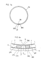
- La figure 1 est une vue en plan selon l'axe de la jante.
- La figure 2a est une vue en coupe diamétrale selon II-II.
- Les figures 2b et 2c sont des vues de détails en coupe, à plus grande échelle, montrant le profil de la jante, dans une coupe diamétrale au niveau d'un oeillet (figure 2c) et dans une coupe au-delà du niveau d'un oeillet (figure 2b).
- Les figures 3 à 10 illustrent schématiquement le procédé de fabrication selon l'invention.
- La figure 3 représente une première étape préliminaire.
- La figure 4 est une vue en coupe transversale selon IV-IV de la figure 3.
- Les figures 5a, 5b et 5c illustrent les différentes phases d'une deuxième étape préliminaire, la figure 5a illustrant la phase avant le cintrage, la figure 5b illustrant le cintrage proprement dit, tandis que la figure 5c illustre la phase après cintrage.
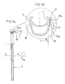
- Les figures 6a, 6b, 6c et 6d illustrent une troisième étape préliminaire.
- Les figures 7a et 7b illustrent une première étape annexe.
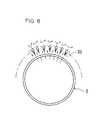
- La figure 8 illustre une deuxième étape annexe.
- Les figures 9a, 9b, 9c, 9d, 9e, 9f illustrent l'étape complémentaire selon l'invention.
- La figure 10 montre une autre des étapes annexes du procédé.
- La jante selon l'invention et portant la référence générale (1) est destinée à être équipée de façon connue en soi, de rayons, d'un moyeu et d'un pneu pour constituer la roue d'un cycle. La jante proprement dite (2) de plan général de symétrie (P) est un anneau de grand diamètre d'axe (XX'), réalisé par un profilé en aluminium qui présente une section ayant la forme générale d'un U ouvert vers la périphérie extérieure, dans lequel est destiné à prendre place le pneu et la chambre à air éventuelle. Le profilé possède deux ailes (3,4) latérales avantageusement symétriques par rapport au plan (P) reliées par deux parois transversales (5, 6) espacées l'une de l'autre : une paroi inférieure (5) et une paroi intermédiaire (6). Les deux parois (5, 6) étant légèrement courbes et formant avec des ailes latérales (3, 4) un caisson périphérique (7) destiné notamment à assurer la tenue mécanique et la rigidité de lajante, et notamment permettre aussi l'accrochage des rayons (non représenté). Notons par ailleurs que l'extrémité de chacune des ailes (3, 4) comprend une saillie locale (8, 9) destinée à retenir le pneu équipant la roue. Par ailleurs, la paroi intermédiaire (6) comprend un logement circulaire périphérique de retenue et de centrage (10) comprenant deux parois verticales (11, 12) et un fond (13) concave et dont la courbure est par exemple un cercle. De plus, les parois intérieures latérales (14, 15) du caisson (7) sont au moins en partie formées par des portions de paroi internes (16, 17) sensiblement parallèles au plan (P) de symétrie générale, tandis que leurs prolongements sont convergents.
- Selon l'invention, les flancs (18, 19) de ladite jante sont usinés par enlèvement de matière pour constituer des faces diamétrales de freinage (20, 21) qui sont planes et soit parallèles entre elles et parallèles au plan de symétrie (P), soit convergentes vers l'intérieur de la roue même, comme cela est représenté à la figure 9b et qui est une solution préférée, voire convergentes vers l'extérieur (EX). Ainsi, chacune des faces peut former avec le plan (P) un angle (A) d'environ 1,5 degrés. La retenue des rayons se fait de façon classique par des oeillets (22a, 22b) fixés dans des trous (23a, 23b) réalisés dans les parois inférieure (5) et intermédiaire (6) du caisson selon des axes (YY') correspondant à ceux des rayons destinés à y être retenus. Bien entendu, la jante comprend un trou (24) destiné au passage de la valve de la chambre à air (figure 1).
- Le procédé de fabrication selon l'invention de la jante est décrit ci-après et illustré schématiquement par les figures 3 à 10.
- Selon ce procédé, les flancs (18, 19) de la jante sont usinés dans une étape complémentaire afin de créer sur lesdits flancs (18, 19) des faces de freinage (20, 21) de caractéristiques dimensionnelles qualitatives parfaites et dont l'état de surface, l'homogénéité et la continuité sont sans reproche. Cette étape d'usinage n'est que complémentaire et fait partie d'un ensemble d'étapes nécessaires faites avant usinage dans des étapes préliminaires ou après usinage dans des étapes ultérieures.
- L'étape complémentaire selon l'invention, illustrée schématiquement aux figures 9a, 9b, 9c, 9d, 9e et 9f, est avantageusement un usinage par enlèvement de matière et par exemple par enlèvement de copeaux grâce à un outil d'usinage. L'usinage peut être du type meulage, rectification, fraisage, mais la solution préférée est celle du tournage en faisant pivoter selon R relativement la jante et/ou l'outil autour de l'axe (XX') de la jante et en déplaçant diamétralement selon F1 ou F2, l'outil d'usinage.
- Avant de décrire plus précisément cette étape complémentaire sur laquelle nous reviendrons plus loin, nous allons décrire ci-après les étapes préliminaires.
- La jante (2) est réalisée principalement et de façon connue, à partir d'un morceau de profilé en aluminium cintré. Ainsi, dans une première étape préliminaire (figures 3, 4), on découpe un morceau (25) de profilé d'aluminium de longueur (L) suffisante pour qu'une fois cintré, le diamètre (D) de la jante puisse être obtenu, et qui présente une section ayant la forme générale d'un U ouvert vers la périphérie extérieure (EX), dans lequel est destiné à prendre place le pneu et la chambre à air éventuelle. Le profilé possède deux ailes (3, 4) latérales avantageusement symétriques par rapport au plan (P) reliées par deux parois transversales (5, 6) espacées l'une de l'autre : une paroi inférieure (5) et une paroi intermédiaire (6). Les deux parois (5, 6) étant légèrement courbes et formant avec des ailes latérales (3, 4) un caisson périphérique (7) destiné notamment à assurer la rigidité de la jante. Notons par ailleurs que l'extrémité extérieure de chacune des ailes (3, 4) comprend une saillie locale (8, 9) s'étendant vers le plan (P) de symétrie, destinée à retenir le pneu équipant la roue. Par ailleurs, la paroi intermédiaire (6) comprend un logement circulaire périphérique de retenue et de centrage (10) comprenant deux parois verticales (11, 12) et un fond (13) concave et dont la courbure est par exemple un cercle. De plus, les parois intérieures latérales (14, 15) du caisson (7) sont au moins en partie formées par des portions de parois internes (16, 17) sensiblement parallèles au plan (P) de symétrie générale. Les flancs latéraux (18, 19) étant légèrement courbes.
- Dans une deuxième étape préliminaire illustrée aux figures 5a, 5b et 5c, on cintre le morceau de profilé (25) pour former un anneau circulaire (26) et mettre bout à bout ses deux extrémités (27, 28). L'opération de cintrage se faisant grâce à une cintreuse (250) qui comprend par exemple deux galets d'entraînement (251a, 251b), un galet de cintrage (252) et un galet de guidage (253). La figure 5a représente la phase d'introduction du profilé dans la cintreuse (250). La figure 5b illustre la phase de cintrage proprement dite. La figure 5c illustre le morceau de profilé une fois cintré, les deux extrémités (27, 28) se faisant face.
- Dans une troisième étape préliminaire, on solidarise ensemble les deux extrémités (27, 28) en les soudant bout à bout, comme cela est illustré aux figures 6a, 6b, 6c et 6d. L'opération de soudure se fait par exemple électriquement par étincelage, ce qui provoque la fusion des deux extrémités en contact et les lie ensemble par fusion et liaison intime de la matière. Cette fusion de la matière due à l'échauffement généré par le passage du courant provoque la formation d'un cordon de soudure faisant un bourrelet périphérique (29) au niveau de la jointure (31). L'opération de soudage se fait grâce à une soudeuse du type à étincelage (260) comprenant deux mâchoires (261a, 261 b) destinées à retenir les deux extrémités (270, 280) du morceau cintré (26). Les mâchoires sont alimentées en courant électrique et se rapprochent pendant l'opération, mutuellement selon (f1,f2), l'espace initial (e1 ) entre les mâchoires diminuant progressivement pour devenir (e2) inférieur à (e1). Parallèlement à l'opération de soudage, on introduit (figure 6a) dans le caisson (7) de chaque extrémité (270, 280), une éclisse (271, 281) retenue dans ledit caisson par un poinçonnage (272, 282) de la paroi (6) correspondante. Chaque éclisse est enfoncée dans le caisson d'une longueur telle qu'en fin de soudure, les deux faces (273,283) soient en contact. Ainsi, la distance initiale (E) est égale à (e1) moins (e2). La présence des deux éclisses empêche l'effondrement des cloisons du caisson (7) lors de l'opération de soudage.
- Dans la suite du procédé, il est prévu une première étape annexe destinée à supprimer le bourrelet de soudure (29), avant que l'usinage des flancs ne soit fait dans l'étape complémentaire selon l'invention. Ainsi, dans cette première étape annexe (figures 7a, 7b), le cordon de soudure (29) est usiné extérieurement au profil et notamment au niveau des flancs, par une fraise (30) se déplaçant tout autour du profil au niveau de la soudure et dans le plan de jonction (31) (figure 7b). Par ailleurs, le cordon est aussi supprimé à l'intérieur du profil entre les ailes (3, 4) et le fond (5) grâce à une autre fraise pivotante (32) (figure 7a).
- Dans une deuxième étape annexe illustrée schématiquement à la figure 8 faisant suite, on réalise les perçages de la jante pour réaliser les trous (23a, 23b) respectivement dans les parois inférieures (5) et intermédiaires (6). A cet effet, on utilise un ou plusieurs forets épaulés (33) d'axe incliné successivement d'un côté et de l'autre, afin que les deux nappes de rayons y soient retenues dans de bonnes conditions. Par ailleurs, dans cette opération, on réalise le trou (24) destiné au passage de la valve, qui est disposé avantageusement diamétralement par rapport au plan de jonction et de soudage (31).
- On procède ensuite à l'étape complémentaire selon l'invention, illustrée aux figures 9a, 9b, 9c, 9d, 9e et 9f, qui consiste à usiner les flancs (18, 19) de la jante ainsi formée. La figure 9a est une vue en coupe avant usinage, tandis que la figure 9b est une vue en coupe après usinage. L'usinage est réalisé par enlèvement de la matière latérale (180, 190) pour réaliser des faces diamétrales (20, 21) de freinage parfaites aussi bien du point de vue état de surface que du point de vue dimensionnel. L'usinage peut être de tout type et peut par exemple être du tournage en faisant tourner la jante ou l'outil autour de l'axe (XX') de la roue et en déplaçant diamétralement l'outil (34a, 34b) diamétralement selon F1 et vers le centre, comme cela est représenté, ou vers l'extérieur selon F2. On réalise l'usinage d'un des flancs, et ensuite l'autre, ou les deux simultanément.
- L'usinage permet d'une part d'obtenir un dimensionnement en largeur (I) précis, d'autre part de créer des faces de freinage (20, 21) parfaites, homogènes et continues, tant dans leur aspect dimensionnel que dans leur aspect état de surface. En effet, l'usinage permet en plus de faire disparaître la zone de jonction, et permet ainsi un freinage parfait sans à-coups.
- Les faces de freinage (20,21) sont avantageusement symétriques par rapport au plan (P) et peuvent être parallèles entre elles, mais aussi convergeantes vers l'axe de la roue, comme cela est illustré, pourfor- mer par exemple un angle (A) d'environ 3 degrés, mais elles peuvent être tout aussi bien divergentes.
- Dans une étape ultérieure ou troisième étape annexe, on fait subira à la jante ainsi usinée, un traitement anodique ou anodisation, réalisée de façon classique (non représentée).
- Dans une étape suivante finale, on réalise l'oeil- letage en plaçant les différents rivets (22a, 22b), comme cela est représenté à la figure 10, et grâce à une bouterolle (35).
- Dans une variante de procédé, on peut, après l'étape complémentaire d'usinage, procéder à une opération annexe qui consiste à faire un dépôt de céramique sur les deux flancs (20, 21 ) ainsi usinés. Cette opération se faisant donc entre l'opération d'usinage et l'étape finale correspondant à celle de la pose des oeillets. Par contre, l'anodisation faite après l'usinage dans le procédé précédent est effectuée selon cette variante, avant l'usinage des flancs (18, 19).
- Il va de soi que l'invention n'est pas limitée à une jante formée par un profilé en aluminium, mais qu'elle peut être de tout autre type et notamment en matériau composite ou autre.
- Bien entendu, l'invention n'est pas limitée aux modes de réalisation décrits et représentés à titre d'exemples, mais elle comprend aussi tous les équivalents techniques ainsi que leurs combinaisons.
Claims (18)
Priority Applications (1)
| Application Number | Priority Date | Filing Date | Title |
|---|---|---|---|
| DE9320953U DE9320953U1 (de) | 1992-07-15 | 1993-07-01 | Radfelge |
Applications Claiming Priority (2)
| Application Number | Priority Date | Filing Date | Title |
|---|---|---|---|
| FR9208892A FR2693672B1 (fr) | 1992-07-15 | 1992-07-15 | Procédé de fabrication d'une jante pour cycle et jante réalisée avec ce procédé. |
| FR9208892 | 1992-07-15 |
Publications (2)
| Publication Number | Publication Date |
|---|---|
| EP0579525A1 true EP0579525A1 (fr) | 1994-01-19 |
| EP0579525B1 EP0579525B1 (fr) | 1996-01-10 |
Family
ID=9432029
Family Applications (1)
| Application Number | Title | Priority Date | Filing Date |
|---|---|---|---|
| EP19930401704 Expired - Lifetime EP0579525B1 (fr) | 1992-07-15 | 1993-07-01 | Procédé de fabrication d'une jante pour cycle et jante réalisée avec ce procédé |
Country Status (4)
| Country | Link |
|---|---|
| EP (1) | EP0579525B1 (fr) |
| JP (2) | JPH06182629A (fr) |
| DE (2) | DE579525T1 (fr) |
| FR (1) | FR2693672B1 (fr) |
Cited By (32)
| Publication number | Priority date | Publication date | Assignee | Title |
|---|---|---|---|---|
| FR2727356A1 (fr) * | 1994-11-30 | 1996-05-31 | Mavic Sa | Jante de velo et roue comprenant une telle jante |
| FR2727355A1 (fr) * | 1994-11-30 | 1996-05-31 | Mavic Sa | Procede de fabrication d'une jante pour cycle et jante realisee avec ce procede |
| FR2733459A1 (fr) * | 1995-04-28 | 1996-10-31 | Mavic Sa | Jante pour cycle utilisant un manchon de raccordement et manchon de raccordement pour une telle jante |
| DE19523043A1 (de) * | 1995-06-24 | 1997-01-02 | Hans Schauff Fahrradfabrik | Laufradfelge |
| WO1997026143A1 (fr) * | 1996-01-12 | 1997-07-24 | 'alesa', 'l'alliage Leger Et Ses Applications' | Jante de bicyclette en alliage leger |
| WO1997045276A1 (fr) * | 1996-05-28 | 1997-12-04 | Marino Quaresimin | Roue pour vehicules |
| WO1998003296A1 (fr) * | 1996-07-19 | 1998-01-29 | Trek Bicycle Corporation | Procede de soudage de profiles metalliques electroconducteurs |
| EP0860301A1 (fr) * | 1997-02-21 | 1998-08-26 | "Alesa", "l'Alliage Léger et ses Applications" N.V. | Améliorations aux connections rayon-jante pour roues à rayons |
| US5829299A (en) * | 1994-10-05 | 1998-11-03 | Holland Mechanics B.V. | Method and apparatus for making nipple holes in a double-walled hollow wheel rim of a spoke wheel |
| US6119746A (en) * | 1997-07-25 | 2000-09-19 | Mavic S.A. | Valve and rim for bicycle wheel provided for a tubeless assembly |
| US6216344B1 (en) | 1996-07-12 | 2001-04-17 | Mavic S.A. | Method for boring a spoke rim and for providing an insert for the bored rim |
| US6224165B1 (en) | 1996-07-12 | 2001-05-01 | Mavic S.A. | Method for boring a spoke rim, rim bored according to the method, insert adapted to equip the rim, and wheel especially cycle rim |
| DE4444044C2 (de) * | 1994-12-10 | 2001-11-08 | Josef Hasberg | Felgenrad für Fahrräder u. dgl. |
| US6443533B2 (en) | 1997-07-25 | 2002-09-03 | Mavic S.A. | Bicycle rim structure provided for a tubeless assembly and bicycle wheel |
| FR2825319A1 (fr) * | 2001-06-05 | 2002-12-06 | Mavic Sa | Procede de construction d'une roue a rayons sous tension et roue a rayons sous tension destinee a un vehicule a deux roues |
| US6568766B1 (en) | 2001-02-28 | 2003-05-27 | Shimano Inc. | Bicycle rim |
| WO2003045710A1 (fr) | 2001-11-29 | 2003-06-05 | Compositech, Inc. | Jante composite de bicyclette a surfaces de freinage sans joint |
| US6582029B2 (en) | 2001-05-25 | 2003-06-24 | Shimano Inc. | Bicycle rim |
| US6955509B2 (en) * | 2002-06-20 | 2005-10-18 | Dt Swiss Inc. | Method for producing a rim and a rim, particularly for a bicycle |
| US6961999B2 (en) | 2003-02-25 | 2005-11-08 | William B Shook | Lightweight bicycle wheel rim and method for producing it |
| EP1990215A1 (fr) * | 2007-05-07 | 2008-11-12 | CAMPAGNOLO S.r.l. | Jante et roue de bicyclette avec ailes disposant d'une ondulation compensée localisée |
| US7555838B2 (en) | 2005-09-23 | 2009-07-07 | Shook William B | Method for producing a lightweight bicycle wheel rim |
| US7918514B2 (en) | 2007-05-30 | 2011-04-05 | Campagnolo, S.R.L. | Rim for a bicycle wheel made from composite material with a wear indicator and wheel comprising such a rim |
| US8002362B2 (en) | 2004-02-17 | 2011-08-23 | Trek Bicycle Corporation | Optimal thermal properties in light weight and high performance braking composite clincher or tubular tire bicycle wheel rim |
| US8007052B2 (en) | 2004-08-31 | 2011-08-30 | Campagnolo, S.R.L. | Rim for a spoked bicycle wheel, wheel and manufacturing method |
| US8066336B2 (en) | 2003-06-26 | 2011-11-29 | Campagnolo S.R.L. | Lightened rim for a bicycle wheel and method for manufacturing such a rim |
| FR2985219A1 (fr) * | 2012-01-04 | 2013-07-05 | Mavic Sas | Jante pour roue de cycle et son procede de fabrication |
| EP2612766A1 (fr) | 2012-01-04 | 2013-07-10 | Mavic S.A.S. | Jante pour roue de cycle et son procédé de fabrication |
| EP2612768A1 (fr) | 2012-01-04 | 2013-07-10 | Mavic S.A.S. | Jante pour roue de cycle et son procédé de fabrication |
| FR3028802A1 (fr) * | 2014-11-26 | 2016-05-27 | Mavic Sas | Jante pour roue de cycle et son procede de fabrication |
| US9688097B2 (en) | 2003-08-11 | 2017-06-27 | Campagnolo S.R.L. | Method for producing composite bicycle rim |
| US9757979B2 (en) | 2007-11-26 | 2017-09-12 | Campagnolo S.R.L. | Rim for a bicycle wheel and bicycle wheel comprising such a rim |
Families Citing this family (8)
| Publication number | Priority date | Publication date | Assignee | Title |
|---|---|---|---|---|
| AUPQ350599A0 (en) * | 1999-10-19 | 1999-11-11 | Drage, Kevin Linane | Modified wheel rim |
| FR2816548B1 (fr) | 2000-11-14 | 2003-02-28 | Salomon Sa | Procede de fabrication d'une jante de bicyclette prevue pour un montage sans chambre a air et jante obtenue par la mise en oeuvre du procede |
| KR100448558B1 (ko) * | 2001-12-28 | 2004-09-13 | 주식회사 우연 | 복합재료 자전거림의 금형장치 및 이를 이용한 제조기계 |
| ATE390297T1 (de) | 2002-11-08 | 2008-04-15 | Campagnolo Srl | Verfahren zur herstellung eines speichenrads für fahrräder |
| ITMI20072232A1 (it) | 2007-11-26 | 2009-05-27 | Campagnolo Srl | Cerchio per ruota di bicicletta e ruota di bicicletta comprendente tale cerchio |
| ATE509779T1 (de) | 2008-03-14 | 2011-06-15 | Campagnolo Srl | Radfelge aus verbundmaterial für ein schlauchloses fahrradrad und ein mit einer solchen radfelge ausgestattetes schlauchloses fahrradrad |
| ITMI20122229A1 (it) * | 2012-12-21 | 2014-06-22 | Campagnolo Srl | Componente di bicicletta comprendente un corpo in alluminio ed un corpo in materiale composito, e metodo di fabbricazione di tale componente |
| CN105935862A (zh) * | 2016-05-31 | 2016-09-14 | 浙江安然电气科技有限公司 | 电瓶车钢圈成型工艺 |
Citations (7)
| Publication number | Priority date | Publication date | Assignee | Title |
|---|---|---|---|---|
| US1518283A (en) * | 1922-05-10 | 1924-12-09 | Gen Motors Corp | Rim-burring machine |
| US3433327A (en) * | 1966-06-29 | 1969-03-18 | Thionville Laminoirs A Froid | Braking surface for the rims of bicycle wheels |
| FR2190547A1 (fr) * | 1972-07-05 | 1974-02-01 | Fontijne Bv Machine | |
| US4142394A (en) * | 1975-11-21 | 1979-03-06 | Holland Mechanics B.V. | Apparatus for forming circularly bent articles from a straight profiled strip |
| JPS57205060A (en) * | 1981-06-15 | 1982-12-16 | Araya Kogyo Kk | Finishing method of recessed groove |
| FR2614844A1 (fr) * | 1987-05-04 | 1988-11-10 | Micromag Spa | Roue de bicyclette |
| JPH1122701A (ja) * | 1997-07-04 | 1999-01-26 | Nok Corp | 圧力容器のガスプラグおよびそのガスプラグ用ガス供給装置 |
Family Cites Families (2)
| Publication number | Priority date | Publication date | Assignee | Title |
|---|---|---|---|---|
| JPS54147166A (en) * | 1978-05-11 | 1979-11-17 | Araya Kougiyou Kk | Production of rim |
| US4989657A (en) * | 1985-04-08 | 1991-02-05 | Center Line Tool Co., Inc. | Modular vehicle wheel |
-
1992
- 1992-07-15 FR FR9208892A patent/FR2693672B1/fr not_active Expired - Fee Related
-
1993
- 1993-07-01 EP EP19930401704 patent/EP0579525B1/fr not_active Expired - Lifetime
- 1993-07-01 DE DE1993401704 patent/DE579525T1/de active Pending
- 1993-07-01 DE DE69301288T patent/DE69301288D1/de not_active Expired - Lifetime
- 1993-07-14 JP JP17416593A patent/JPH06182629A/ja active Pending
-
1995
- 1995-07-28 JP JP1995007832U patent/JP3025849U/ja not_active Expired - Lifetime
Patent Citations (7)
| Publication number | Priority date | Publication date | Assignee | Title |
|---|---|---|---|---|
| US1518283A (en) * | 1922-05-10 | 1924-12-09 | Gen Motors Corp | Rim-burring machine |
| US3433327A (en) * | 1966-06-29 | 1969-03-18 | Thionville Laminoirs A Froid | Braking surface for the rims of bicycle wheels |
| FR2190547A1 (fr) * | 1972-07-05 | 1974-02-01 | Fontijne Bv Machine | |
| US4142394A (en) * | 1975-11-21 | 1979-03-06 | Holland Mechanics B.V. | Apparatus for forming circularly bent articles from a straight profiled strip |
| JPS57205060A (en) * | 1981-06-15 | 1982-12-16 | Araya Kogyo Kk | Finishing method of recessed groove |
| FR2614844A1 (fr) * | 1987-05-04 | 1988-11-10 | Micromag Spa | Roue de bicyclette |
| JPH1122701A (ja) * | 1997-07-04 | 1999-01-26 | Nok Corp | 圧力容器のガスプラグおよびそのガスプラグ用ガス供給装置 |
Non-Patent Citations (2)
| Title |
|---|
| PATENT ABSTRACTS OF JAPAN vol. 007, no. 059 (M - 199) 11 March 1983 (1983-03-11) * |
| PATENT ABSTRACTS OF JAPAN vol. 013, no. 365 (M - 859) 15 August 1989 (1989-08-15) * |
Cited By (48)
| Publication number | Priority date | Publication date | Assignee | Title |
|---|---|---|---|---|
| US5829299A (en) * | 1994-10-05 | 1998-11-03 | Holland Mechanics B.V. | Method and apparatus for making nipple holes in a double-walled hollow wheel rim of a spoke wheel |
| FR2727355A1 (fr) * | 1994-11-30 | 1996-05-31 | Mavic Sa | Procede de fabrication d'une jante pour cycle et jante realisee avec ce procede |
| EP0715001A1 (fr) * | 1994-11-30 | 1996-06-05 | Mavic S.A. | Procédé de fabrication d'une jante pour cycle et jante réalisée avec ce procédé |
| EP0714792A1 (fr) * | 1994-11-30 | 1996-06-05 | Mavic S.A. | Jante de vélo et roue comprenant une telle jante |
| FR2727356A1 (fr) * | 1994-11-30 | 1996-05-31 | Mavic Sa | Jante de velo et roue comprenant une telle jante |
| US5651591A (en) * | 1994-11-30 | 1997-07-29 | Mavic S.A. | Cycle rim and wheel comprising such a rim |
| DE4444044C2 (de) * | 1994-12-10 | 2001-11-08 | Josef Hasberg | Felgenrad für Fahrräder u. dgl. |
| FR2733459A1 (fr) * | 1995-04-28 | 1996-10-31 | Mavic Sa | Jante pour cycle utilisant un manchon de raccordement et manchon de raccordement pour une telle jante |
| WO1996033876A1 (fr) * | 1995-04-28 | 1996-10-31 | Mavic S.A. | Jante pour cycle utilisant un manchon de raccordement et manchon de raccordement pour une telle jante |
| DE19523043A1 (de) * | 1995-06-24 | 1997-01-02 | Hans Schauff Fahrradfabrik | Laufradfelge |
| DE19523043B4 (de) * | 1995-06-24 | 2005-07-07 | Schauff, Jan | Fahrradfelge und Verfahren zu deren Herstellung |
| WO1997026143A1 (fr) * | 1996-01-12 | 1997-07-24 | 'alesa', 'l'alliage Leger Et Ses Applications' | Jante de bicyclette en alliage leger |
| WO1997045276A1 (fr) * | 1996-05-28 | 1997-12-04 | Marino Quaresimin | Roue pour vehicules |
| US6216344B1 (en) | 1996-07-12 | 2001-04-17 | Mavic S.A. | Method for boring a spoke rim and for providing an insert for the bored rim |
| US6224165B1 (en) | 1996-07-12 | 2001-05-01 | Mavic S.A. | Method for boring a spoke rim, rim bored according to the method, insert adapted to equip the rim, and wheel especially cycle rim |
| US6378953B2 (en) | 1996-07-12 | 2002-04-30 | Mavic S.A. | Bicycle rim for a tension spoke bicycle wheel |
| WO1998003296A1 (fr) * | 1996-07-19 | 1998-01-29 | Trek Bicycle Corporation | Procede de soudage de profiles metalliques electroconducteurs |
| US5734142A (en) * | 1996-07-19 | 1998-03-31 | Trek Bicycle Corporation | Method of welding electrically conductive metal profiles |
| BE1010941A3 (nl) * | 1997-02-21 | 1999-03-02 | Alesa | Verbeteringen aan spaak-velg verbindingen voor spaakwielen. |
| EP0860301A1 (fr) * | 1997-02-21 | 1998-08-26 | "Alesa", "l'Alliage Léger et ses Applications" N.V. | Améliorations aux connections rayon-jante pour roues à rayons |
| US6119746A (en) * | 1997-07-25 | 2000-09-19 | Mavic S.A. | Valve and rim for bicycle wheel provided for a tubeless assembly |
| US6443533B2 (en) | 1997-07-25 | 2002-09-03 | Mavic S.A. | Bicycle rim structure provided for a tubeless assembly and bicycle wheel |
| US6641227B2 (en) | 1997-07-25 | 2003-11-04 | Mavic S.A. | Bicycle rim structure provided for a tubeless assembly and a bicycle wheel incorporating same |
| US6568766B1 (en) | 2001-02-28 | 2003-05-27 | Shimano Inc. | Bicycle rim |
| US6582029B2 (en) | 2001-05-25 | 2003-06-24 | Shimano Inc. | Bicycle rim |
| FR2825319A1 (fr) * | 2001-06-05 | 2002-12-06 | Mavic Sa | Procede de construction d'une roue a rayons sous tension et roue a rayons sous tension destinee a un vehicule a deux roues |
| EP1448398A4 (fr) * | 2001-11-29 | 2008-07-09 | Compositech Inc | Jante composite de bicyclette a surfaces de freinage sans joint |
| WO2003045710A1 (fr) | 2001-11-29 | 2003-06-05 | Compositech, Inc. | Jante composite de bicyclette a surfaces de freinage sans joint |
| US6955509B2 (en) * | 2002-06-20 | 2005-10-18 | Dt Swiss Inc. | Method for producing a rim and a rim, particularly for a bicycle |
| US7179026B2 (en) | 2002-06-20 | 2007-02-20 | Dt Swiss Inc. | Method for producing a rim and a rim, particularly for a bicycle |
| US6961999B2 (en) | 2003-02-25 | 2005-11-08 | William B Shook | Lightweight bicycle wheel rim and method for producing it |
| US8066336B2 (en) | 2003-06-26 | 2011-11-29 | Campagnolo S.R.L. | Lightened rim for a bicycle wheel and method for manufacturing such a rim |
| US9688097B2 (en) | 2003-08-11 | 2017-06-27 | Campagnolo S.R.L. | Method for producing composite bicycle rim |
| US8002362B2 (en) | 2004-02-17 | 2011-08-23 | Trek Bicycle Corporation | Optimal thermal properties in light weight and high performance braking composite clincher or tubular tire bicycle wheel rim |
| US8007052B2 (en) | 2004-08-31 | 2011-08-30 | Campagnolo, S.R.L. | Rim for a spoked bicycle wheel, wheel and manufacturing method |
| US7555838B2 (en) | 2005-09-23 | 2009-07-07 | Shook William B | Method for producing a lightweight bicycle wheel rim |
| EP1990215A1 (fr) * | 2007-05-07 | 2008-11-12 | CAMPAGNOLO S.r.l. | Jante et roue de bicyclette avec ailes disposant d'une ondulation compensée localisée |
| US7918514B2 (en) | 2007-05-30 | 2011-04-05 | Campagnolo, S.R.L. | Rim for a bicycle wheel made from composite material with a wear indicator and wheel comprising such a rim |
| US9757979B2 (en) | 2007-11-26 | 2017-09-12 | Campagnolo S.R.L. | Rim for a bicycle wheel and bicycle wheel comprising such a rim |
| US9186718B2 (en) | 2012-01-04 | 2015-11-17 | Mavic S.A.S. | Cycle wheel rim and method of manufacture |
| EP2612768A1 (fr) | 2012-01-04 | 2013-07-10 | Mavic S.A.S. | Jante pour roue de cycle et son procédé de fabrication |
| EP2612766A1 (fr) | 2012-01-04 | 2013-07-10 | Mavic S.A.S. | Jante pour roue de cycle et son procédé de fabrication |
| US9493032B2 (en) | 2012-01-04 | 2016-11-15 | Mavic S.A.S. | Cycle wheel rim and method of manufacture |
| US9511626B2 (en) | 2012-01-04 | 2016-12-06 | Mavic S.A.S. | Cycle wheel rim and method of manufacture |
| EP2612767A1 (fr) | 2012-01-04 | 2013-07-10 | Mavic S.A.S. | Jante pour roue de cycle et son procédé de fabrication |
| FR2985219A1 (fr) * | 2012-01-04 | 2013-07-05 | Mavic Sas | Jante pour roue de cycle et son procede de fabrication |
| FR3028802A1 (fr) * | 2014-11-26 | 2016-05-27 | Mavic Sas | Jante pour roue de cycle et son procede de fabrication |
| EP3031617A1 (fr) * | 2014-11-26 | 2016-06-15 | Mavic S.A.S. | Jante pour roue de cycle et son procédé de fabrication |
Also Published As
| Publication number | Publication date |
|---|---|
| DE579525T1 (de) | 1995-06-29 |
| EP0579525B1 (fr) | 1996-01-10 |
| JPH06182629A (ja) | 1994-07-05 |
| FR2693672A1 (fr) | 1994-01-21 |
| JP3025849U (ja) | 1996-06-25 |
| DE69301288D1 (de) | 1996-02-22 |
| FR2693672B1 (fr) | 1994-11-04 |
Similar Documents
| Publication | Publication Date | Title |
|---|---|---|
| EP0579525B1 (fr) | Procédé de fabrication d'une jante pour cycle et jante réalisée avec ce procédé | |
| EP0714792B1 (fr) | Jante de vélo et roue comprenant une telle jante | |
| EP0818328B1 (fr) | Procédé de perçage d'une jante à rayon, jante percée selon le procédé, insert adapté pour équiper la jante, et roue notamment de cycle | |
| FR2820686A1 (fr) | Roue de cycle a rayons | |
| FR2751029A1 (fr) | Silencieux de pot d'echappement | |
| EP2612767B1 (fr) | Jante pour roue de cycle et son procédé de fabrication | |
| FR2809781A1 (fr) | Organe de fixation a empreinte d'extremite dans une partie terminale filetee | |
| FR2660716A1 (fr) | Piece de moyeu pour un disque d'embrayage et procede de fabrication de celle-ci. | |
| EP1136713B1 (fr) | Palier composite à double roulement à billes, procédé pour son montage, et outil pour la réalisation d'une paire de bagues dudit palier | |
| EP2612768B1 (fr) | Jante pour roue de cycle et son procédé de fabrication | |
| EP1299251A1 (fr) | Roue pour vehicule a assemblage sous siege | |
| FR2602735A1 (fr) | Couronne de roue libre a plusieurs vitesses pour bicyclette | |
| EP3115226B1 (fr) | Pièce de centrage pour un roulement de roue, roulement et assemblage de roue de véhicule associés | |
| EP1671811B1 (fr) | Roue allégée en particulier pour machines agricoles | |
| EP0464449B1 (fr) | Procédé d'assemblage d'un disque de roue à une jante et roue ainsi obtenue | |
| FR2985218A1 (fr) | Jante pour roue de cycle et son procede de fabrication | |
| EP1551648B1 (fr) | Jante de roue constituee de deux structures assemblees | |
| WO2002047923A2 (fr) | Roue avec jante ayant des sieges inclines vers l'exterieur et realisee par un procede d'extrusion | |
| FR2905085A1 (fr) | Procede de fabrication d'un corps de moyeu pour une roue a rayons et moyeu realise selon le procede | |
| FR2582586A1 (fr) | Roue en alliage leger pour vehicule, dont la jante est constituee d'au moins deux couronnes associees l'une a l'autre en continu et procede pour la fabrication d'une telle roue | |
| FR3081378A1 (fr) | Piece, kit et ensemble de support de moyeu d'une roue motrice de vehicule, et procedes de fabrication et d'assemblage associes | |
| EP1538007B1 (fr) | Dispositif de roulage à plat pour véhicule automobile et ensemble monté l'incorporant | |
| EP0142058A1 (fr) | Jante en plusieurs pièces comportant un cercle de blocage perfectionné | |
| EP1398431A1 (fr) | Procédé de fabrication d'un élément vertical d'échafaudage, et élément ainsi obtenu | |
| WO1996033876A1 (fr) | Jante pour cycle utilisant un manchon de raccordement et manchon de raccordement pour une telle jante |
Legal Events
| Date | Code | Title | Description |
|---|---|---|---|
| PUAI | Public reference made under article 153(3) epc to a published international application that has entered the european phase |
Free format text: ORIGINAL CODE: 0009012 |
|
| AK | Designated contracting states |
Kind code of ref document: A1 Designated state(s): BE CH DE ES GB IT LI NL |
|
| 17P | Request for examination filed |
Effective date: 19940525 |
|
| 17Q | First examination report despatched |
Effective date: 19950220 |
|
| ITCL | It: translation for ep claims filed |
Representative=s name: AVV. GIOVANNI LECCE & C. |
|
| DET | De: translation of patent claims | ||
| GRAA | (expected) grant |
Free format text: ORIGINAL CODE: 0009210 |
|
| AK | Designated contracting states |
Kind code of ref document: B1 Designated state(s): BE CH DE ES GB IT LI NL |
|
| PG25 | Lapsed in a contracting state [announced via postgrant information from national office to epo] |
Ref country code: NL Free format text: LAPSE BECAUSE OF FAILURE TO SUBMIT A TRANSLATION OF THE DESCRIPTION OR TO PAY THE FEE WITHIN THE PRESCRIBED TIME-LIMIT Effective date: 19960110 Ref country code: IT Free format text: LAPSE BECAUSE OF FAILURE TO SUBMIT A TRANSLATION OF THE DESCRIPTION OR TO PAY THE FEE WITHIN THE PRESCRIBED TIME-LIMIT;WARNING: LAPSES OF ITALIAN PATENTS WITH EFFECTIVE DATE BEFORE 2007 MAY HAVE OCCURRED AT ANY TIME BEFORE 2007. THE CORRECT EFFECTIVE DATE MAY BE DIFFERENT FROM THE ONE RECORDED. Effective date: 19960110 Ref country code: GB Effective date: 19960110 Ref country code: ES Free format text: THE PATENT HAS BEEN ANNULLED BY A DECISION OF A NATIONAL AUTHORITY Effective date: 19960110 |
|
| REF | Corresponds to: |
Ref document number: 69301288 Country of ref document: DE Date of ref document: 19960222 |
|
| PG25 | Lapsed in a contracting state [announced via postgrant information from national office to epo] |
Ref country code: DE Effective date: 19960411 |
|
| NLV1 | Nl: lapsed or annulled due to failure to fulfill the requirements of art. 29p and 29m of the patents act | ||
| GBV | Gb: ep patent (uk) treated as always having been void in accordance with gb section 77(7)/1977 [no translation filed] |
Effective date: 19960110 |
|
| PG25 | Lapsed in a contracting state [announced via postgrant information from national office to epo] |
Ref country code: LI Effective date: 19960731 Ref country code: CH Effective date: 19960731 Ref country code: BE Effective date: 19960731 |
|
| PLBE | No opposition filed within time limit |
Free format text: ORIGINAL CODE: 0009261 |
|
| STAA | Information on the status of an ep patent application or granted ep patent |
Free format text: STATUS: NO OPPOSITION FILED WITHIN TIME LIMIT |
|
| 26N | No opposition filed | ||
| BERE | Be: lapsed |
Owner name: S.A. MAVIC Effective date: 19960731 |
|
| REG | Reference to a national code |
Ref country code: CH Ref legal event code: PL |