EP0579964A1 - Handsäge mit Absaugvorrichtung - Google Patents
Handsäge mit Absaugvorrichtung Download PDFInfo
- Publication number
- EP0579964A1 EP0579964A1 EP93109903A EP93109903A EP0579964A1 EP 0579964 A1 EP0579964 A1 EP 0579964A1 EP 93109903 A EP93109903 A EP 93109903A EP 93109903 A EP93109903 A EP 93109903A EP 0579964 A1 EP0579964 A1 EP 0579964A1
- Authority
- EP
- European Patent Office
- Prior art keywords
- collection container
- chip collection
- fan
- motor
- housing
- Prior art date
- Legal status (The legal status is an assumption and is not a legal conclusion. Google has not performed a legal analysis and makes no representation as to the accuracy of the status listed.)
- Granted
Links
Images

Classifications
-
- B—PERFORMING OPERATIONS; TRANSPORTING
- B23—MACHINE TOOLS; METAL-WORKING NOT OTHERWISE PROVIDED FOR
- B23Q—DETAILS, COMPONENTS, OR ACCESSORIES FOR MACHINE TOOLS, e.g. ARRANGEMENTS FOR COPYING OR CONTROLLING; MACHINE TOOLS IN GENERAL CHARACTERISED BY THE CONSTRUCTION OF PARTICULAR DETAILS OR COMPONENTS; COMBINATIONS OR ASSOCIATIONS OF METAL-WORKING MACHINES, NOT DIRECTED TO A PARTICULAR RESULT
- B23Q11/00—Accessories fitted to machine tools for keeping tools or parts of the machine in good working condition or for cooling work; Safety devices specially combined with or arranged in, or specially adapted for use in connection with, machine tools
- B23Q11/0042—Devices for removing chips
- B23Q11/0046—Devices for removing chips by sucking
Definitions
- the invention is based on a hand saw according to the preamble of claim 1.
- a hand saw according to the preamble of claim 1.
- From DE 37 17 585 A1 a similar motor-operated hand saw is known which has a suction channel attached to the saw blade, into which blown air generated by the drive motor of the saw is introduced.
- this blown air is not sufficient for chip evacuation, but only has a supporting effect.
- An additional suction blower to be connected from the outside with a hose that hinders work is required.
- the hand saw according to the invention with the characterizing features of claim 1 has the advantage that the handiness of the saw is significantly improved by the suction of the sawdust only by its own power without external units.
- the design has the further advantage that the chips are not pulled through the fan wheel. Blocking of the fan wheel by jamming coarse chips is thus avoided.
- the saw according to the invention has the further advantage that the motor shaft need not be extended. Because of the lower deflection, this results in sufficiently high critical speeds without the need to lower the idling speed in order to reduce performance.
- the construction according to claim 2 has the advantage that the air flow generated by the cooling fan is used to generate the suction air.
- the chip collection container covers all cooling air inlet openings of the motor housing in an airtight manner. This avoids suction of ambient air that reduces suction power.
- the arrangement of the chip collection container at the rear end of the motor housing has the advantage over, for example, a lateral arrangement that sawing close to the edge can be carried out without restriction.
- the embodiment according to claim 6 is more robust in operation because of the separate air passages. It is particularly advantageous that the chip collection container is completely removable for emptying.
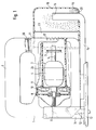
- Figure 1 shows a partial longitudinal section of a first embodiment.
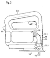
- Figure 2 shows a view and
- Figure 3 shows a partial cross section of a second embodiment.
- a hand saw designed as a jigsaw has a preferably double-shell motor housing 1 with a handle 2.
- the handle 2 can be molded in one piece onto the housing shells.
- a motor 3 is accommodated in the motor housing 1, the rotor 4 of which has a motor shaft 5 with an output pinion 6 and a collector 7.
- the output pinion 6 is in engagement with a known gear, omitted in the drawing, for generating the lifting movement of the tool.
- the motor drives a saw blade 12 via the gear, not shown. This passes through a slot of a base plate 13 which is connected to the housing 1 and which can be placed on a workpiece.
- the saw blade 12 is surrounded by a transparent cover 14 above the base plate 13.
- a suction channel 15 is formed in the center of the base plate 13, directly behind the saw blade 12. However, this can also be arranged in the lower part of the motor housing 1.
- the suction channel 15 - it can be made in several parts telescopically - runs in the sawing direction of the jigsaw parallel to the motor shaft 5 to the rear, bends upwards and projects with its mouth 16 into a chip collection container 18.
- the extracted chips 19 collect at the bottom 20 of the chip collection container 18 at.
- the chip collection container 18 connects to the motor housing 1 in an airtight manner.
- a circumferential seal 21 is provided.
- it is removably connected to the motor housing 1 by means of snap closures (not shown) in such a way that the air intake openings 22 provided there are completely covered.
- an air-permeable but dust-holding filter 23 for example made of cotton.
- the air intake openings 22 open into a cooling air housing 24 surrounding the motor 3.
- the cooling air housing 24 can be integrally molded onto the motor housing 1 or inserted into the latter. In any case, it is sealed off from other housing parts, such as in particular from the handle 2, for example with a seal 26.
- the cooling air housing 24 continues to the fan 10 and opens into the fan housing 9 on the suction side 1 on the exhaust side of the fan 10 outlet openings, not shown.
- the fan 10 is used for engine cooling and dust extraction at the same time.
- it may be reinforced by a flow-optimized fan housing 9 according to DE-A-40 03 029 or by slightly enlarged fan blades.
- This does not extend the length of the motor shaft 5 or only extends it by a few millimeters.
- the chips 19 produced during sawing are sucked through the suction channel 15 and, after leaving, fall into the chip collection container 18 without moving the mouth 16.
- the strong deflection of the air flow after leaving the mouth 16 to the air intake openings 22 supports the failure of the chips.
- they are retained by the filter 23, while the cleaned air is sucked in as cooling air through the air intake openings 22 into the cooling air housing 24.
- the chips 19 are therefore not sucked through the fan 10, where, in particular, long chips that occur when sawing softwood in the direction of the fibers could otherwise get caught between the fan blades and the fan housing.
- the electrical parts of the motor 3, such as the collector 7, are also protected against sawdust and dust.
- the chip collection container 18 is removed from the motor housing 1 for emptying. Cooling the engine 3 is also maintained when working without chip extraction, ie when the chip collection container 18 is removed.
- the at least two-part suction channel (15) can be inserted telescopically in the direction of the saw blade (12).
- a motor housing 101 has a handle 102. Inside the motor housing 101 there is a motor 103 shown in FIG. 2 with a rotor 104, motor shaft 105, output pinion 106 and collector 107.
- a fan wheel 108 with double-sided blading 108.1 and 108.2 sits on the motor shaft 105.
- a functional two-part fan housing 109 surrounding the fan wheel which consists of a cooling fan housing 109.1 and a dust fan housing 109.2, completes the fan 110.
- FIG. 2 also shows a saw blade 112 driven by the motor 103, a base plate 113 and a transparent cover 114.
- a suction channel 115 consists of an intake port 115.1 opening to the side of the saw blade and a flexible short hose 115.2 which projects into a clamping collecting container 118.
- the chip collection container 118 is arranged on the side of the motor housing 101 and can be removed for emptying. It is connected to the dust fan housing 109.2 via a suction opening 122.
- the cooling air flows through openings 125 in the motor housing 101 into a cooling air housing 124 which is integral with the cooling fan housing 109.1.
- the function of the second exemplary embodiment differs from the first in that the air paths for the cooling air and the chip extraction up to the fan 110 are separated.
- the two-part fan wheel 108 also serves to separate the air flows within the fan with its double blading.
- the suction air flows being combined in the fan housing.
- the suction channel 115 is relatively short, which keeps the flow losses low.
- the invention is also applicable to other types of saws. In the case of circular saws, for example, this would only require a change in the suction channel, which would then lead from the protective hood collecting the chips to a chip collecting container preferably located on the top of the motor housing.
Landscapes
- Engineering & Computer Science (AREA)
- Mechanical Engineering (AREA)
- Sawing (AREA)
- Auxiliary Devices For Machine Tools (AREA)
Abstract
Description
- Die Erfindung geht aus von einer Handsäge nach dem Oberbegriff des Anspruchs 1. Aus der DE 37 17 585 A1 ist eine ähnliche motorbetriebene Handsäge bekannt, die einen am Sägeblatt ansetzenden Absaugkanal aufweist, in den vom Antriebsmotor der Säge erzeugte Blasluft eingeleitet wird. Diese Blasluft reicht jedoch zur Spanabfuhr nicht aus, sondern wirkt nur unterstützend. Ein zusätzliches, von außen anzuschließendes Sauggebläse mit beim Arbeiten hinderlichem Schlauch ist erforderlich.
- Die erfindungsgemäße Handsäge mit den kennzeichnenden Merkmalen des Anspruchs 1 hat demgegenüber den Vorteil, daß durch die Absaugung der Sägespäne ausschließlich aus eigener Kraft ohne Fremdaggregate die Handlichkeit der Säge erheblich verbessert wird.
- Die Bauweise hat den weiteren Vorteil, daß die Späne nicht durch das Lüfterrad hindurchgezogen werden. Damit wird ein Blockieren des Lüfterrades durch Einklemmen grober Späne vermieden.
- Gegenüber einer denkbaren Lösung mit zwei Lüfterrädern auf einer Welle, d. h. eines für die Kühlung und eines für die Staubabsaugung hat die erfindungsgemäße Säge den weiteren Vorteil, daß die Motorwelle nicht verlängert zu werden braucht. Dies ergibt wegen der geringeren Durchbiegung ausreichend hohe kritische Drehzahlen, ohne daß eine leistungsmindernde Absenkung der Leerlaufdrehzahl erforderlich wird.
- Durch die in den abhängigen Ansprüchen aufgeführten Maßnahmen sind vorteilhafte Weiterbildungen und Verbesserungen der im Anspruch 1 angegebenen Handwerkzeugmaschine möglich. Die Bauweise nach Anspruch 2 hat den Vorteil, daß zur Erzeugung der Saugluft der vom Kühlgebläse erzeugte Luftstrom ausgenutzt wird. Der Spansammelbehälter deckt dabei in anmontiertem Zustand alle Kühllufteintrittsöffnungen des Motorgehäuses luftdicht ab. Dadurch wird ein die Saugleistung verminderndes Ansaugen von Umgebungsluft vermieden. Die Anordnung des Spansammelbehälters am hinteren Ende des Motorgehäuses hat gegenüber zum Beispiel seitlicher Anordnung den Vorteil, daß randnahes Sägen ohne Einschränkung durchgeführt werden kann. Die Ausführung nach Anspruch 6 ist wegen der getrennten Luftwege im Betrieb robuster. Besonders vorteilhaft ist es, daß der Spansammelbehälter zum Entleeren vollständig abnehmbar ist.
- Zwei Ausführungsbeispiele der Erfindung sind in der Zeichnung dargestellt und in der nachfolgenden Beschreibung näher erläutert. Figur 1 zeigt einen Teillängsschnitt eines ersten Ausführungsbeispiels. Figur 2 zeigt eine Ansicht und Figur 3 einen Teil-Querschnitt eines zweiten Ausführungsbeispiels.
- Eine als Stichsäge ausgebildete Handsäge weist ein vorzugsweise zweischaliges Motorgehäuse 1 mit einem Handgriff 2 auf. Der Handgriff 2 kann einstückig an die Gehäuseschalen angespritzt sein. In dem Motorgehäuse 1 ist unter anderem ein Motor 3 untergebracht, dessen Rotor 4 eine Motorwelle 5 mit Abtriebsritzel 6 und Kollektor 7 aufweist. Das Abtriebsritzel 6 steht mit einem an sich bekannten, in der Zeichnung weggelassenen Getriebe zur Erzeugung der Hubbewegung des Werkzeugs in Eingriff. Auf der Motorwelle 5 sitzt nahe dem Ritzel 6 ein Lüfterrad 8, das zusammen mit einem geeigneten Lüftergehäuse 9 einen Lüfter 10 bildet.
- Der Motor treibt über das nicht gezeigte Getriebe ein Sägeblatt 12 an. Dieses durchgreift einen Schlitz einer mit dem Gehäuse 1 verbundenen Fußplatte 13, die auf ein Werkstück aufsetzbar ist. Das Sägeblatt 12 ist oberhalb der Fußplatte 13 von einer durchsichtigen Abdeckhaube 14 umgeben. In dem Raum zwischen Motorgehäuse 1 und Fußplatte 13 ist mittig auf der Fußplatte 13 ein direkt hinter dem Sägeblatt 12 ansetzender Absaugkanal 15 ausgebildet. Dieser kann jedoch auch in dem unteren Teil des Motorgehäuses 1 angeordnet sein. Der Absaugkanal 15 - er kann mehrteilig teleskopartig ausgebildet sein - verläuft in Sägerichtung der Stichsäge parallel zur Motorwelle 5 nach hinten, knickt nach oben ab und ragt mit seiner Mündung 16 in einen Spansammelbehälter 18. Die abgesaugten Späne 19 sammeln sich am Boden 20 des Spansammelbehälters 18 an.
- Der Spansammelbehälter 18 schließt luftdicht an das Motorgehäuse 1 an. Dazu ist eine umlaufende Dichtung 21 vorgesehen. Er ist beispielsweise mittels nicht dargestellter Schnappverschlüsse mit dem Motorgehäuse 1 abnehmbar so verbunden, daß die dort vorgesehenen Luftansaugöffnungen 22 vollständig abgedeckt sind. Zwischen dem Motorgehäuse 1 und dem Spansammelbehälter 18 befindet sich, insbesondere die Luftansaugöffnungen 22 überdeckend, ein luftdurchlässiges, aber Staub abhaltendes Filter 23, beispielsweise aus Baumwolle. Die Luftansaugöffnungen 22 münden in ein den Motor 3 umgebendes Kühlluftgehäuse 24. Dieses kann einstückig an das Motorgehäuse 1 angespritzt oder aber in dieses eingesetzt sein. In jedem Fall ist es gegenüber anderen Gehäuseteilen, wie insbesondere gegenüber dem Handgriff 2 abgedichtet, zum Beispiel mit einer Dichtung 26. Das Kühlluftgehäuse 24 setzt sich bis zum Lüfter 10 fort und mündet saugseitig in das Lüftergehäuse 9. Zum Austritt der angesaugten Luft weist das Motorgehäuse 1 an der Abluftseite des Lüfters 10 nicht dargestellte Austrittsöffnungen auf.
- Der Lüfter 10 dient gleichzeitig der Motorkühlung und der Staubabsaugung. Dazu ist er gegenüber reinen Kühllüftern ggf. verstärkt durch ein strömungsoptimiertes Lüftergehäuse 9 gemäß DE-A-40 03 029 oder durch etwas vergrößerte Lüfterschaufeln. Dadurch wird jedoch die Länge der Motorwelle 5 nicht oder nur um wenige Millimeter verlängert. Die beim Sägen entstehenden Späne 19 werden durch den Absaugkanal 15 gesaugt und fallen nach Verlassen in den Spansammelbehälter 18, ohne die Mündung 16 zu verlegen. Die starke Umlenkung des Luftstromes nach Verlassen der Mündung 16 zu den Luftansaugöffnungen 22 unterstütz das Ausfallen der Späne. Im Spansammelbehälter 18 werden sie von dem Filter 23 zurückgehalten, während die Luft gereinigt als Kühlluft durch die Luftansaugöffnungen 22 in das Kühlluftgehäuse 24 eingesaugt wird. Die Späne 19 werden also nicht durch den Lüfter 10 gesaugt, wo insbesondere lange, beim Sägen von Weichholz in Faserrichtung entstehende Späne sich sonst zwischen Lüfterschaufeln und Lüftergehäuse einklemmen könnten. Auch die elektrischen Teile des Motors 3, wie der Kollektor 7, sind vor Sägespänen und -mehl geschützt. Zum Entleeren wird der Spansammelbehälter 18 vom Motorgehäuse 1 abgenommen. Die Kühlung des Motors 3 wird auch beim Arbeiten ohne Spanabsaugung, d.h. bei abgezogenem Spansammelbehälter 18 aufrechterhalten. In diesem Fall ist der mindestens zweiteilige Absaugkanal (15) teleskopartig in Richtung auf das Sägeblatt (12) einschiebbar.
- Im zweiten Ausführungsbeispiel nach den Figuren 2 und 3 sind für gleiche Teile gegenüber dem ersten Ausführungsbeispiel um 100 erhöhte Bezugszahlen verwendet. Die Unterschiede liegen nur in der Anordnung der Absaugeinrichtung an der Säge und in einem modifizierten Lüfterrad. Ein Motorgehäuse 101 weist einen Handgriff 102. Im Inneren des Motorgehäuse 101 befindet sich ein in Figur 2 gezeigter Motor 103 mit Rotor 104, Motorwelle 105, Abtriebsritzel 106 und Kollektor 107. Auf der Motorwelle 105 sitzt ein Lüfterrad 108 mit doppelseitiger Beschaufelung 108.1 und 108.2. Ein das Lüfterrad umgebendes funktional zweiteiligen Lüftergehäuse 109, das aus einem Kühllüftergehäuse 109.1 und einem Staublüftergehäuse 109.2 besteht, vervollständigt den Lüfter 110.
- Aus Figur 2 ist weiter ein vom Motor 103 angetriebenes Sägeblatt 112, eine Fußplatte 113 und eine durchsichtige Abdeckhaube 114 erkennbar. Ein Absaugkanal 115 besteht aus einem seitlich des Sägeblatts mündenden Ansaugstutzen 115.1 und einem flexiblen kurzen Schlauch 115.2, der in einen Spannsammelbehälter 118 hineinragt. Der Spansammelbehälter 118 ist seitlich am Motorgehäuse 101 angeordnet und zur Entleerung abnehmbar. Er steht über eine Ansaugöffnung 122 mit dem Staublüftergehäuse 109.2 in Verbindung. Die Kühlluft strömt durch Öffnungen 125 im Motorgehäuse 101 in ein Kühlluftgehäuse 124, das einstückig mit dem Kühllüftergehäuse 109.1 ist.
- Die Funktion des zweiten Ausführungsbeipiels unterscheidet sich dadurch vom ersten, daß die Luftwege für die Kühlluft und die Spanabsaugung bis zum Lüfter 110 getrennt sind. Auch innerhalb des Lüfters dient das zweiteilige Lüfterrad 108 mit seiner doppelten Beschaufelung der Trennung der Luftströme. Hier könnte gegebenenfalls aber auch ein einfaches Lüfterrad Verwendung finden, wobei die Saugluftströme im Lüftergehäuse vereinigt werden. Der Absaugkanal 115 ist relativ kurz, was die Strömungsverluste gering hält.
- Die Erfindung ist auch auf andere Bauarten von Sägen anwendbar. Bei Kreissägen beispielsweise wäre dazu nur eine Änderung des Absaugkanals notwendig, der dann von der die Späne sammelnden Schutzhaube zu einem vorzugsweise auf dem Motorgehäuse oben aufsitzenden Spansammelbehälter führen würde.
Claims (11)
- Handsäge, insbesondere Stichsäge, mit einem Motorgehäuse (1), in dem ein Motor (3, 103) mit Lüfter (10, 110) untergebracht ist, einer Fußplatte (13, 113), einem über diese hinausragenden Sageblatt (12, 112) und einem am Sägeblatt (12, 112) ansetzenden Absaugkanal (15, 115), dadurch gekennzeichnet, daß der Absaugkanal (15, 115) unmittelbar in einen Spansammelbehälter (18, 118) mündet und der Lüfter (10, 110) im Saugluftstrom dem Spansammelbehälter (18, 118) nachgeschaltet ist.
- Handsäge nach Anspruch 1, dadurch gekennzeichnet, daß der Saugluftstrom im Spansammelbehälter (18) stark, insbesondere um mindestens etwa 90° umgelenkt wird.
- Handsäge nach einem der Ansprüche 1 oder 2, dadurch gekennzeichnet, daß der Lüfter (10) seine auch zur Kühlung des Motors (3) verwendete Luft über den Absaugkanal (15) durch den Spansammelbehälter (18) hindurch ansaugt.
- Handsäge nach einem der Ansprüche 1 bis 3, dadurch gekennzeichnet, daß der Spansammelbehälter (18) die Luftansaugöffnungen (22) für die Kühlluft am Motorgehäuse (1) luftdicht abdeckt.
- Stichsäge nach einem der vorhergehenden Ansprüche, dadurch gekennzeichnet, daß der Spansammelbehälter (18) am dem Sägeblatt (12) abgewandten Ende der Maschine in Sägerichtung hinter dem Motorgehäuse (1) angeordnet ist.
- Handsäge nach einem der vorhergehenden Ansprüche, dadurch gekennzeichnet, daß der Motor (3) von einem gegebenenfalls einstückig mit dem Motorgehäuse (1) ausgebildeten Kühlluftgehäuse (24) umgeben ist, das gegenüber anderen Gehäuseteilen, insbesondere dem Bereich eines Handgriffs (2), luftdicht abgedichtet ist.
- Handsäge nach Anspruch 1, dadurch gekennzeichnet, daß vor dem Lüfter (110) die Kühlluft- von den Saugluftwegen getrennt sind und der Spansammelbehälter (118) seitlich des Motorgehäuses (110) angebracht ist.
- Handsäge nach einem der vorhergehenden Ansprüche, dadurch gekennzeichnet, daß der Absaugkanal (15) in dem Raum zwischen Fußplatte (13) und Motorgehäuse (1) angeordnet ist.
- Handsäge nach einem der vorhergehenden Ansprüche, dadurch gekennzeichnet, daß der Spansammelbehälter (18) abnehmbar ist.
- Handsäge nach einem der vorhergehenden Ansprüche, dadurch gekennzeichnet, daß die Mündung (16) des Absaugkanals (15) innerhalb des Spansammelbehälters (18) soweit oberhalb des Bodens (20) angeordnet ist, daß bereits gesammelte Späne (19) die Mündung (16) nicht verlegen.
- Handsäge nach einem der vorhergehenden Ansprüche, dadurch gekennzeichnet, daß zwischen Kühlluftgehäuse (24) und Spansammelbehälter (18) ein luftdurchlässiges Filter (23) angeordnet ist.
Applications Claiming Priority (2)
| Application Number | Priority Date | Filing Date | Title |
|---|---|---|---|
| DE4224094 | 1992-07-22 | ||
| DE4224094A DE4224094A1 (de) | 1992-07-22 | 1992-07-22 | Handsäge mit Absaugvorrichtung |
Publications (2)
| Publication Number | Publication Date |
|---|---|
| EP0579964A1 true EP0579964A1 (de) | 1994-01-26 |
| EP0579964B1 EP0579964B1 (de) | 1999-02-24 |
Family
ID=6463784
Family Applications (1)
| Application Number | Title | Priority Date | Filing Date |
|---|---|---|---|
| EP93109903A Expired - Lifetime EP0579964B1 (de) | 1992-07-22 | 1993-06-22 | Handsäge mit Absaugvorrichtung |
Country Status (3)
| Country | Link |
|---|---|
| EP (1) | EP0579964B1 (de) |
| JP (1) | JPH06155155A (de) |
| DE (2) | DE4224094A1 (de) |
Cited By (10)
| Publication number | Priority date | Publication date | Assignee | Title |
|---|---|---|---|---|
| WO2002034462A1 (de) * | 2000-10-28 | 2002-05-02 | Robert Bosch Gmbh | Handwerkzeugmaschine mit einer staubabsaugeinrichtung |
| WO2007080003A1 (de) * | 2005-12-28 | 2007-07-19 | Robert Bosch Gmbh | Handwerkzeugmaschine |
| US7979989B2 (en) * | 2006-09-04 | 2011-07-19 | Robert Bosch Gmbh | Handheld power tool |
| CN108839151A (zh) * | 2018-05-03 | 2018-11-20 | 张冰冰 | 一种可防火除尘的木材加工用切割装置 |
| US10293421B2 (en) | 2016-09-15 | 2019-05-21 | Dustless Depot, Llc | Circular saw dust collection shroud |
| USD908149S1 (en) | 2018-10-23 | 2021-01-19 | Dustless Depot Llc | Angle grinder dust shroud with variable position slots for mounting brackets |
| US20210046631A1 (en) * | 2019-08-13 | 2021-02-18 | Yamabiko Corporation | Electric working tool |
| US11123839B2 (en) | 2018-10-23 | 2021-09-21 | Dustless Depot Llc | Grinder dust shroud with input shaft gasket and adjustable mounting mechanism |
| US11273505B2 (en) | 2019-03-27 | 2022-03-15 | Dustless Depot, Llc | Circular saw dust collection shroud |
| CN115091258A (zh) * | 2022-07-25 | 2022-09-23 | 浙江宁巍机械科技有限公司 | 一种便于粉屑收集的铸件切割机 |
Families Citing this family (14)
| Publication number | Priority date | Publication date | Assignee | Title |
|---|---|---|---|---|
| US5822864A (en) | 1996-05-31 | 1998-10-20 | Black & Decker, Inc. | Viewing window for circular saw guard |
| JP3899311B2 (ja) * | 2002-12-16 | 2007-03-28 | 株式会社マキタ | 切断機 |
| JP4561787B2 (ja) * | 2007-07-20 | 2010-10-13 | パナソニック電工株式会社 | 切断工具 |
| JP4561788B2 (ja) * | 2007-07-20 | 2010-10-13 | パナソニック電工株式会社 | 切断工具 |
| US8177606B2 (en) | 2008-01-15 | 2012-05-15 | Dustless Depot, Llc | Dust shroud for rotary tools |
| US8137165B2 (en) | 2008-01-15 | 2012-03-20 | Dust Collection Products, Llc | Dust shroud with adjustable mounting mechanism |
| JP5115415B2 (ja) * | 2008-09-12 | 2013-01-09 | 日立工機株式会社 | 携帯用切断機 |
| US8702478B2 (en) | 2009-05-08 | 2014-04-22 | Michael Loveless | Angle grinder dust shroud with unitary adjustable mounting collar |
| US8381711B2 (en) | 2009-06-16 | 2013-02-26 | Dustless Depot, Llc | Universal dust collection shroud for high speed gas powered saws |
| US8523637B2 (en) | 2009-07-21 | 2013-09-03 | Dustless Depot, Llc | Angle grinder dust shroud with slideable access hatch |
| US8561512B2 (en) | 2009-08-18 | 2013-10-22 | Dustless Depot Llc | Cutoff saw and stand with integrated dust filtration system |
| US9038275B2 (en) | 2011-09-07 | 2015-05-26 | Dustless Depot, Llc | Reciprocating saw dust shroud |
| CN105583908A (zh) * | 2014-10-24 | 2016-05-18 | 苏州宝时得电动工具有限公司 | 切割机 |
| USD816453S1 (en) | 2016-09-15 | 2018-05-01 | Dustless Depot, Llc | Circular saw dust shroud |
Citations (5)
| Publication number | Priority date | Publication date | Assignee | Title |
|---|---|---|---|---|
| DE644011C (de) * | 1935-03-30 | 1937-04-22 | Carl Sauer | Nutenfraesmaschine |
| DE694801C (de) * | 1938-12-23 | 1940-08-08 | Festo Maschf Stoll G | Staubsauger fuer Holzschleifmaschinen |
| US4209069A (en) * | 1974-09-03 | 1980-06-24 | Lockheed Corporation | Drills with chip collectors |
| EP0347631A2 (de) * | 1988-06-18 | 1989-12-27 | Karl M. Reich, Maschinenfabrik GmbH | Stichsäge mit Absaugung |
| WO1991011297A1 (de) * | 1990-02-02 | 1991-08-08 | Robert Bosch Gmbh | Handgeführte werkzeugmaschine mit radialgebläse |
Family Cites Families (3)
| Publication number | Priority date | Publication date | Assignee | Title |
|---|---|---|---|---|
| DE3420442A1 (de) * | 1984-06-01 | 1985-12-05 | Festo KG, 7300 Esslingen | Stichsaege |
| DE3712236A1 (de) * | 1987-04-10 | 1988-10-27 | Bosch Gmbh Robert | Stichsaege |
| JPH0644652Y2 (ja) * | 1990-03-15 | 1994-11-16 | リョービ株式会社 | 集塵装置付き電動切断カッター |
-
1992
- 1992-07-22 DE DE4224094A patent/DE4224094A1/de not_active Withdrawn
-
1993
- 1993-06-22 DE DE59309387T patent/DE59309387D1/de not_active Expired - Fee Related
- 1993-06-22 EP EP93109903A patent/EP0579964B1/de not_active Expired - Lifetime
- 1993-07-21 JP JP5180090A patent/JPH06155155A/ja active Pending
Patent Citations (5)
| Publication number | Priority date | Publication date | Assignee | Title |
|---|---|---|---|---|
| DE644011C (de) * | 1935-03-30 | 1937-04-22 | Carl Sauer | Nutenfraesmaschine |
| DE694801C (de) * | 1938-12-23 | 1940-08-08 | Festo Maschf Stoll G | Staubsauger fuer Holzschleifmaschinen |
| US4209069A (en) * | 1974-09-03 | 1980-06-24 | Lockheed Corporation | Drills with chip collectors |
| EP0347631A2 (de) * | 1988-06-18 | 1989-12-27 | Karl M. Reich, Maschinenfabrik GmbH | Stichsäge mit Absaugung |
| WO1991011297A1 (de) * | 1990-02-02 | 1991-08-08 | Robert Bosch Gmbh | Handgeführte werkzeugmaschine mit radialgebläse |
Cited By (13)
| Publication number | Priority date | Publication date | Assignee | Title |
|---|---|---|---|---|
| WO2002034462A1 (de) * | 2000-10-28 | 2002-05-02 | Robert Bosch Gmbh | Handwerkzeugmaschine mit einer staubabsaugeinrichtung |
| US6848985B2 (en) * | 2000-10-28 | 2005-02-01 | Robert Bosch Gmbh | Hand tool comprising a dust suction device |
| WO2007080003A1 (de) * | 2005-12-28 | 2007-07-19 | Robert Bosch Gmbh | Handwerkzeugmaschine |
| US7979989B2 (en) * | 2006-09-04 | 2011-07-19 | Robert Bosch Gmbh | Handheld power tool |
| US10293421B2 (en) | 2016-09-15 | 2019-05-21 | Dustless Depot, Llc | Circular saw dust collection shroud |
| CN108839151A (zh) * | 2018-05-03 | 2018-11-20 | 张冰冰 | 一种可防火除尘的木材加工用切割装置 |
| USD908149S1 (en) | 2018-10-23 | 2021-01-19 | Dustless Depot Llc | Angle grinder dust shroud with variable position slots for mounting brackets |
| US11123839B2 (en) | 2018-10-23 | 2021-09-21 | Dustless Depot Llc | Grinder dust shroud with input shaft gasket and adjustable mounting mechanism |
| US11273505B2 (en) | 2019-03-27 | 2022-03-15 | Dustless Depot, Llc | Circular saw dust collection shroud |
| US20210046631A1 (en) * | 2019-08-13 | 2021-02-18 | Yamabiko Corporation | Electric working tool |
| US11701769B2 (en) * | 2019-08-13 | 2023-07-18 | Yamabiko Corporation | Electric working tool |
| CN115091258A (zh) * | 2022-07-25 | 2022-09-23 | 浙江宁巍机械科技有限公司 | 一种便于粉屑收集的铸件切割机 |
| CN115091258B (zh) * | 2022-07-25 | 2023-12-01 | 浙江宁巍机械科技有限公司 | 一种便于粉屑收集的铸件切割机 |
Also Published As
| Publication number | Publication date |
|---|---|
| JPH06155155A (ja) | 1994-06-03 |
| EP0579964B1 (de) | 1999-02-24 |
| DE59309387D1 (de) | 1999-04-01 |
| DE4224094A1 (de) | 1994-01-27 |
Similar Documents
| Publication | Publication Date | Title |
|---|---|---|
| EP0579964A1 (de) | Handsäge mit Absaugvorrichtung | |
| EP1332020B1 (de) | Handwerkzeugmaschine mit einer staubabsaugeinrichtung | |
| DE10036458B4 (de) | Staubfangvorrichtung für eine Kreissäge | |
| DE112012004557T5 (de) | Tischsägen-Staubabsaugungsanordnung | |
| DE102004029220A1 (de) | Handwerkzeuggerät mit Staubabsaugmodul | |
| EP1068092B1 (de) | Bodenverdichtungsmaschine | |
| DE102007056381A1 (de) | Handwerkzeugmaschine | |
| DE10128790A1 (de) | Ansaugvorrichtung für die Verbrennungsluft eines Verbrennungsmotors in einem handgeführten Arbeitsgerät | |
| EP0449850A1 (de) | Handkreissäge. | |
| DE102009009239B4 (de) | Vorrichtung zur Reinigung von Ansaugluft | |
| DE19701082B4 (de) | Saug-/Blasgerät | |
| EP4491339B1 (de) | Motorkettensäge oder trennschleifer | |
| EP1872916B1 (de) | Elektrohandwerkzeugmaschine mit Saugmodul für eine Staubabscheidevorrichtung | |
| DE112018000849T5 (de) | Luftvorreinigungsbaugruppe und Elektrowerkzeug mit einer derartigen Luftvorreinigungsbaugruppe | |
| WO2007080003A1 (de) | Handwerkzeugmaschine | |
| DE3525092C2 (de) | ||
| DE69331841T2 (de) | Rasenmäher | |
| DE3615736C2 (de) | ||
| DE4202195A1 (de) | Motorbetriebenes handwerkzeug mit integrierter staubabsaugung | |
| DE202009017053U1 (de) | Staubsaugervorrichtung | |
| EP1697087B1 (de) | Elektrohandwerkzeugmaschine | |
| EP4450231A1 (de) | Elektrisches arbeitsgerät | |
| EP2679828A2 (de) | Staubsaugergebläse und Staubsauger mit einem Staubsaugergebläse | |
| EP4230352B1 (de) | Tragbares arbeitsgerät | |
| DE10049500B4 (de) | Werkzeugmaschine |
Legal Events
| Date | Code | Title | Description |
|---|---|---|---|
| PUAI | Public reference made under article 153(3) epc to a published international application that has entered the european phase |
Free format text: ORIGINAL CODE: 0009012 |
|
| AK | Designated contracting states |
Kind code of ref document: A1 Designated state(s): CH DE FR GB IT LI NL |
|
| 17P | Request for examination filed |
Effective date: 19940708 |
|
| 17Q | First examination report despatched |
Effective date: 19951220 |
|
| GRAG | Despatch of communication of intention to grant |
Free format text: ORIGINAL CODE: EPIDOS AGRA |
|
| GRAG | Despatch of communication of intention to grant |
Free format text: ORIGINAL CODE: EPIDOS AGRA |
|
| GRAH | Despatch of communication of intention to grant a patent |
Free format text: ORIGINAL CODE: EPIDOS IGRA |
|
| GRAH | Despatch of communication of intention to grant a patent |
Free format text: ORIGINAL CODE: EPIDOS IGRA |
|
| GRAA | (expected) grant |
Free format text: ORIGINAL CODE: 0009210 |
|
| AK | Designated contracting states |
Kind code of ref document: B1 Designated state(s): CH DE FR GB IT LI NL |
|
| REG | Reference to a national code |
Ref country code: CH Ref legal event code: NV Representative=s name: SCINTILLA AG, DIREKTION Ref country code: CH Ref legal event code: EP |
|
| REF | Corresponds to: |
Ref document number: 59309387 Country of ref document: DE Date of ref document: 19990401 |
|
| ET | Fr: translation filed | ||
| ITF | It: translation for a ep patent filed | ||
| GBT | Gb: translation of ep patent filed (gb section 77(6)(a)/1977) |
Effective date: 19990428 |
|
| PLBE | No opposition filed within time limit |
Free format text: ORIGINAL CODE: 0009261 |
|
| STAA | Information on the status of an ep patent application or granted ep patent |
Free format text: STATUS: NO OPPOSITION FILED WITHIN TIME LIMIT |
|
| 26N | No opposition filed | ||
| REG | Reference to a national code |
Ref country code: GB Ref legal event code: IF02 |
|
| PGFP | Annual fee paid to national office [announced via postgrant information from national office to epo] |
Ref country code: NL Payment date: 20030624 Year of fee payment: 11 Ref country code: CH Payment date: 20030624 Year of fee payment: 11 |
|
| PG25 | Lapsed in a contracting state [announced via postgrant information from national office to epo] |
Ref country code: LI Free format text: LAPSE BECAUSE OF NON-PAYMENT OF DUE FEES Effective date: 20040630 Ref country code: CH Free format text: LAPSE BECAUSE OF NON-PAYMENT OF DUE FEES Effective date: 20040630 |
|
| PG25 | Lapsed in a contracting state [announced via postgrant information from national office to epo] |
Ref country code: NL Free format text: LAPSE BECAUSE OF NON-PAYMENT OF DUE FEES Effective date: 20050101 |
|
| REG | Reference to a national code |
Ref country code: CH Ref legal event code: PL |
|
| NLV4 | Nl: lapsed or anulled due to non-payment of the annual fee |
Effective date: 20050101 |
|
| PGFP | Annual fee paid to national office [announced via postgrant information from national office to epo] |
Ref country code: DE Payment date: 20080827 Year of fee payment: 16 |
|
| PGFP | Annual fee paid to national office [announced via postgrant information from national office to epo] |
Ref country code: IT Payment date: 20080627 Year of fee payment: 16 Ref country code: FR Payment date: 20080618 Year of fee payment: 16 |
|
| PGFP | Annual fee paid to national office [announced via postgrant information from national office to epo] |
Ref country code: GB Payment date: 20080624 Year of fee payment: 16 |
|
| GBPC | Gb: european patent ceased through non-payment of renewal fee |
Effective date: 20090622 |
|
| REG | Reference to a national code |
Ref country code: FR Ref legal event code: ST Effective date: 20100226 |
|
| PG25 | Lapsed in a contracting state [announced via postgrant information from national office to epo] |
Ref country code: FR Free format text: LAPSE BECAUSE OF NON-PAYMENT OF DUE FEES Effective date: 20090630 |
|
| PG25 | Lapsed in a contracting state [announced via postgrant information from national office to epo] |
Ref country code: GB Free format text: LAPSE BECAUSE OF NON-PAYMENT OF DUE FEES Effective date: 20090622 |
|
| PG25 | Lapsed in a contracting state [announced via postgrant information from national office to epo] |
Ref country code: DE Free format text: LAPSE BECAUSE OF NON-PAYMENT OF DUE FEES Effective date: 20100101 |
|
| PG25 | Lapsed in a contracting state [announced via postgrant information from national office to epo] |
Ref country code: IT Free format text: LAPSE BECAUSE OF NON-PAYMENT OF DUE FEES Effective date: 20090622 |