EP0579964A1 - Scie portative munie d'un dispositif d'aspiration - Google Patents
Scie portative munie d'un dispositif d'aspiration Download PDFInfo
- Publication number
- EP0579964A1 EP0579964A1 EP93109903A EP93109903A EP0579964A1 EP 0579964 A1 EP0579964 A1 EP 0579964A1 EP 93109903 A EP93109903 A EP 93109903A EP 93109903 A EP93109903 A EP 93109903A EP 0579964 A1 EP0579964 A1 EP 0579964A1
- Authority
- EP
- European Patent Office
- Prior art keywords
- collection container
- chip collection
- fan
- motor
- housing
- Prior art date
- Legal status (The legal status is an assumption and is not a legal conclusion. Google has not performed a legal analysis and makes no representation as to the accuracy of the status listed.)
- Granted
Links
Images

Classifications
-
- B—PERFORMING OPERATIONS; TRANSPORTING
- B23—MACHINE TOOLS; METAL-WORKING NOT OTHERWISE PROVIDED FOR
- B23Q—DETAILS, COMPONENTS, OR ACCESSORIES FOR MACHINE TOOLS, e.g. ARRANGEMENTS FOR COPYING OR CONTROLLING; MACHINE TOOLS IN GENERAL CHARACTERISED BY THE CONSTRUCTION OF PARTICULAR DETAILS OR COMPONENTS; COMBINATIONS OR ASSOCIATIONS OF METAL-WORKING MACHINES, NOT DIRECTED TO A PARTICULAR RESULT
- B23Q11/00—Accessories fitted to machine tools for keeping tools or parts of the machine in good working condition or for cooling work; Safety devices specially combined with or arranged in, or specially adapted for use in connection with, machine tools
- B23Q11/0042—Devices for removing chips
- B23Q11/0046—Devices for removing chips by sucking
Definitions
- the invention is based on a hand saw according to the preamble of claim 1.
- a hand saw according to the preamble of claim 1.
- From DE 37 17 585 A1 a similar motor-operated hand saw is known which has a suction channel attached to the saw blade, into which blown air generated by the drive motor of the saw is introduced.
- this blown air is not sufficient for chip evacuation, but only has a supporting effect.
- An additional suction blower to be connected from the outside with a hose that hinders work is required.
- the hand saw according to the invention with the characterizing features of claim 1 has the advantage that the handiness of the saw is significantly improved by the suction of the sawdust only by its own power without external units.
- the design has the further advantage that the chips are not pulled through the fan wheel. Blocking of the fan wheel by jamming coarse chips is thus avoided.
- the saw according to the invention has the further advantage that the motor shaft need not be extended. Because of the lower deflection, this results in sufficiently high critical speeds without the need to lower the idling speed in order to reduce performance.
- the construction according to claim 2 has the advantage that the air flow generated by the cooling fan is used to generate the suction air.
- the chip collection container covers all cooling air inlet openings of the motor housing in an airtight manner. This avoids suction of ambient air that reduces suction power.
- the arrangement of the chip collection container at the rear end of the motor housing has the advantage over, for example, a lateral arrangement that sawing close to the edge can be carried out without restriction.
- the embodiment according to claim 6 is more robust in operation because of the separate air passages. It is particularly advantageous that the chip collection container is completely removable for emptying.
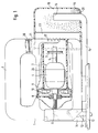
- Figure 1 shows a partial longitudinal section of a first embodiment.
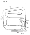
- Figure 2 shows a view and
- Figure 3 shows a partial cross section of a second embodiment.
- a hand saw designed as a jigsaw has a preferably double-shell motor housing 1 with a handle 2.
- the handle 2 can be molded in one piece onto the housing shells.
- a motor 3 is accommodated in the motor housing 1, the rotor 4 of which has a motor shaft 5 with an output pinion 6 and a collector 7.
- the output pinion 6 is in engagement with a known gear, omitted in the drawing, for generating the lifting movement of the tool.
- the motor drives a saw blade 12 via the gear, not shown. This passes through a slot of a base plate 13 which is connected to the housing 1 and which can be placed on a workpiece.
- the saw blade 12 is surrounded by a transparent cover 14 above the base plate 13.
- a suction channel 15 is formed in the center of the base plate 13, directly behind the saw blade 12. However, this can also be arranged in the lower part of the motor housing 1.
- the suction channel 15 - it can be made in several parts telescopically - runs in the sawing direction of the jigsaw parallel to the motor shaft 5 to the rear, bends upwards and projects with its mouth 16 into a chip collection container 18.
- the extracted chips 19 collect at the bottom 20 of the chip collection container 18 at.
- the chip collection container 18 connects to the motor housing 1 in an airtight manner.
- a circumferential seal 21 is provided.
- it is removably connected to the motor housing 1 by means of snap closures (not shown) in such a way that the air intake openings 22 provided there are completely covered.
- an air-permeable but dust-holding filter 23 for example made of cotton.
- the air intake openings 22 open into a cooling air housing 24 surrounding the motor 3.
- the cooling air housing 24 can be integrally molded onto the motor housing 1 or inserted into the latter. In any case, it is sealed off from other housing parts, such as in particular from the handle 2, for example with a seal 26.
- the cooling air housing 24 continues to the fan 10 and opens into the fan housing 9 on the suction side 1 on the exhaust side of the fan 10 outlet openings, not shown.
- the fan 10 is used for engine cooling and dust extraction at the same time.
- it may be reinforced by a flow-optimized fan housing 9 according to DE-A-40 03 029 or by slightly enlarged fan blades.
- This does not extend the length of the motor shaft 5 or only extends it by a few millimeters.
- the chips 19 produced during sawing are sucked through the suction channel 15 and, after leaving, fall into the chip collection container 18 without moving the mouth 16.
- the strong deflection of the air flow after leaving the mouth 16 to the air intake openings 22 supports the failure of the chips.
- they are retained by the filter 23, while the cleaned air is sucked in as cooling air through the air intake openings 22 into the cooling air housing 24.
- the chips 19 are therefore not sucked through the fan 10, where, in particular, long chips that occur when sawing softwood in the direction of the fibers could otherwise get caught between the fan blades and the fan housing.
- the electrical parts of the motor 3, such as the collector 7, are also protected against sawdust and dust.
- the chip collection container 18 is removed from the motor housing 1 for emptying. Cooling the engine 3 is also maintained when working without chip extraction, ie when the chip collection container 18 is removed.
- the at least two-part suction channel (15) can be inserted telescopically in the direction of the saw blade (12).
- a motor housing 101 has a handle 102. Inside the motor housing 101 there is a motor 103 shown in FIG. 2 with a rotor 104, motor shaft 105, output pinion 106 and collector 107.
- a fan wheel 108 with double-sided blading 108.1 and 108.2 sits on the motor shaft 105.
- a functional two-part fan housing 109 surrounding the fan wheel which consists of a cooling fan housing 109.1 and a dust fan housing 109.2, completes the fan 110.
- FIG. 2 also shows a saw blade 112 driven by the motor 103, a base plate 113 and a transparent cover 114.
- a suction channel 115 consists of an intake port 115.1 opening to the side of the saw blade and a flexible short hose 115.2 which projects into a clamping collecting container 118.
- the chip collection container 118 is arranged on the side of the motor housing 101 and can be removed for emptying. It is connected to the dust fan housing 109.2 via a suction opening 122.
- the cooling air flows through openings 125 in the motor housing 101 into a cooling air housing 124 which is integral with the cooling fan housing 109.1.
- the function of the second exemplary embodiment differs from the first in that the air paths for the cooling air and the chip extraction up to the fan 110 are separated.
- the two-part fan wheel 108 also serves to separate the air flows within the fan with its double blading.
- the suction air flows being combined in the fan housing.
- the suction channel 115 is relatively short, which keeps the flow losses low.
- the invention is also applicable to other types of saws. In the case of circular saws, for example, this would only require a change in the suction channel, which would then lead from the protective hood collecting the chips to a chip collecting container preferably located on the top of the motor housing.
Landscapes
- Engineering & Computer Science (AREA)
- Mechanical Engineering (AREA)
- Sawing (AREA)
- Auxiliary Devices For Machine Tools (AREA)
Applications Claiming Priority (2)
| Application Number | Priority Date | Filing Date | Title |
|---|---|---|---|
| DE4224094 | 1992-07-22 | ||
| DE4224094A DE4224094A1 (de) | 1992-07-22 | 1992-07-22 | Handsäge mit Absaugvorrichtung |
Publications (2)
| Publication Number | Publication Date |
|---|---|
| EP0579964A1 true EP0579964A1 (fr) | 1994-01-26 |
| EP0579964B1 EP0579964B1 (fr) | 1999-02-24 |
Family
ID=6463784
Family Applications (1)
| Application Number | Title | Priority Date | Filing Date |
|---|---|---|---|
| EP93109903A Expired - Lifetime EP0579964B1 (fr) | 1992-07-22 | 1993-06-22 | Scie portative munie d'un dispositif d'aspiration |
Country Status (3)
| Country | Link |
|---|---|
| EP (1) | EP0579964B1 (fr) |
| JP (1) | JPH06155155A (fr) |
| DE (2) | DE4224094A1 (fr) |
Cited By (10)
| Publication number | Priority date | Publication date | Assignee | Title |
|---|---|---|---|---|
| WO2002034462A1 (fr) * | 2000-10-28 | 2002-05-02 | Robert Bosch Gmbh | Outil a main comportant un dispositif d'aspiration des poussieres |
| WO2007080003A1 (fr) * | 2005-12-28 | 2007-07-19 | Robert Bosch Gmbh | Machine-outil portative |
| US7979989B2 (en) * | 2006-09-04 | 2011-07-19 | Robert Bosch Gmbh | Handheld power tool |
| CN108839151A (zh) * | 2018-05-03 | 2018-11-20 | 张冰冰 | 一种可防火除尘的木材加工用切割装置 |
| US10293421B2 (en) | 2016-09-15 | 2019-05-21 | Dustless Depot, Llc | Circular saw dust collection shroud |
| USD908149S1 (en) | 2018-10-23 | 2021-01-19 | Dustless Depot Llc | Angle grinder dust shroud with variable position slots for mounting brackets |
| US20210046631A1 (en) * | 2019-08-13 | 2021-02-18 | Yamabiko Corporation | Electric working tool |
| US11123839B2 (en) | 2018-10-23 | 2021-09-21 | Dustless Depot Llc | Grinder dust shroud with input shaft gasket and adjustable mounting mechanism |
| US11273505B2 (en) | 2019-03-27 | 2022-03-15 | Dustless Depot, Llc | Circular saw dust collection shroud |
| CN115091258A (zh) * | 2022-07-25 | 2022-09-23 | 浙江宁巍机械科技有限公司 | 一种便于粉屑收集的铸件切割机 |
Families Citing this family (14)
| Publication number | Priority date | Publication date | Assignee | Title |
|---|---|---|---|---|
| US5822864A (en) | 1996-05-31 | 1998-10-20 | Black & Decker, Inc. | Viewing window for circular saw guard |
| JP3899311B2 (ja) * | 2002-12-16 | 2007-03-28 | 株式会社マキタ | 切断機 |
| JP4561787B2 (ja) * | 2007-07-20 | 2010-10-13 | パナソニック電工株式会社 | 切断工具 |
| JP4561788B2 (ja) * | 2007-07-20 | 2010-10-13 | パナソニック電工株式会社 | 切断工具 |
| US8177606B2 (en) | 2008-01-15 | 2012-05-15 | Dustless Depot, Llc | Dust shroud for rotary tools |
| US8137165B2 (en) | 2008-01-15 | 2012-03-20 | Dust Collection Products, Llc | Dust shroud with adjustable mounting mechanism |
| JP5115415B2 (ja) * | 2008-09-12 | 2013-01-09 | 日立工機株式会社 | 携帯用切断機 |
| US8702478B2 (en) | 2009-05-08 | 2014-04-22 | Michael Loveless | Angle grinder dust shroud with unitary adjustable mounting collar |
| US8381711B2 (en) | 2009-06-16 | 2013-02-26 | Dustless Depot, Llc | Universal dust collection shroud for high speed gas powered saws |
| US8523637B2 (en) | 2009-07-21 | 2013-09-03 | Dustless Depot, Llc | Angle grinder dust shroud with slideable access hatch |
| US8561512B2 (en) | 2009-08-18 | 2013-10-22 | Dustless Depot Llc | Cutoff saw and stand with integrated dust filtration system |
| US9038275B2 (en) | 2011-09-07 | 2015-05-26 | Dustless Depot, Llc | Reciprocating saw dust shroud |
| CN105583908A (zh) * | 2014-10-24 | 2016-05-18 | 苏州宝时得电动工具有限公司 | 切割机 |
| USD816453S1 (en) | 2016-09-15 | 2018-05-01 | Dustless Depot, Llc | Circular saw dust shroud |
Citations (5)
| Publication number | Priority date | Publication date | Assignee | Title |
|---|---|---|---|---|
| DE644011C (de) * | 1935-03-30 | 1937-04-22 | Carl Sauer | Nutenfraesmaschine |
| DE694801C (de) * | 1938-12-23 | 1940-08-08 | Festo Maschf Stoll G | Staubsauger fuer Holzschleifmaschinen |
| US4209069A (en) * | 1974-09-03 | 1980-06-24 | Lockheed Corporation | Drills with chip collectors |
| EP0347631A2 (fr) * | 1988-06-18 | 1989-12-27 | Karl M. Reich, Maschinenfabrik GmbH | Scie sauteuse munie d'une aspiration des copeaux |
| WO1991011297A1 (fr) * | 1990-02-02 | 1991-08-08 | Robert Bosch Gmbh | Machine-outil commandee a la main avec soufflante radiale |
Family Cites Families (3)
| Publication number | Priority date | Publication date | Assignee | Title |
|---|---|---|---|---|
| DE3420442A1 (de) * | 1984-06-01 | 1985-12-05 | Festo KG, 7300 Esslingen | Stichsaege |
| DE3712236A1 (de) * | 1987-04-10 | 1988-10-27 | Bosch Gmbh Robert | Stichsaege |
| JPH0644652Y2 (ja) * | 1990-03-15 | 1994-11-16 | リョービ株式会社 | 集塵装置付き電動切断カッター |
-
1992
- 1992-07-22 DE DE4224094A patent/DE4224094A1/de not_active Withdrawn
-
1993
- 1993-06-22 DE DE59309387T patent/DE59309387D1/de not_active Expired - Fee Related
- 1993-06-22 EP EP93109903A patent/EP0579964B1/fr not_active Expired - Lifetime
- 1993-07-21 JP JP5180090A patent/JPH06155155A/ja active Pending
Patent Citations (5)
| Publication number | Priority date | Publication date | Assignee | Title |
|---|---|---|---|---|
| DE644011C (de) * | 1935-03-30 | 1937-04-22 | Carl Sauer | Nutenfraesmaschine |
| DE694801C (de) * | 1938-12-23 | 1940-08-08 | Festo Maschf Stoll G | Staubsauger fuer Holzschleifmaschinen |
| US4209069A (en) * | 1974-09-03 | 1980-06-24 | Lockheed Corporation | Drills with chip collectors |
| EP0347631A2 (fr) * | 1988-06-18 | 1989-12-27 | Karl M. Reich, Maschinenfabrik GmbH | Scie sauteuse munie d'une aspiration des copeaux |
| WO1991011297A1 (fr) * | 1990-02-02 | 1991-08-08 | Robert Bosch Gmbh | Machine-outil commandee a la main avec soufflante radiale |
Cited By (13)
| Publication number | Priority date | Publication date | Assignee | Title |
|---|---|---|---|---|
| WO2002034462A1 (fr) * | 2000-10-28 | 2002-05-02 | Robert Bosch Gmbh | Outil a main comportant un dispositif d'aspiration des poussieres |
| US6848985B2 (en) * | 2000-10-28 | 2005-02-01 | Robert Bosch Gmbh | Hand tool comprising a dust suction device |
| WO2007080003A1 (fr) * | 2005-12-28 | 2007-07-19 | Robert Bosch Gmbh | Machine-outil portative |
| US7979989B2 (en) * | 2006-09-04 | 2011-07-19 | Robert Bosch Gmbh | Handheld power tool |
| US10293421B2 (en) | 2016-09-15 | 2019-05-21 | Dustless Depot, Llc | Circular saw dust collection shroud |
| CN108839151A (zh) * | 2018-05-03 | 2018-11-20 | 张冰冰 | 一种可防火除尘的木材加工用切割装置 |
| USD908149S1 (en) | 2018-10-23 | 2021-01-19 | Dustless Depot Llc | Angle grinder dust shroud with variable position slots for mounting brackets |
| US11123839B2 (en) | 2018-10-23 | 2021-09-21 | Dustless Depot Llc | Grinder dust shroud with input shaft gasket and adjustable mounting mechanism |
| US11273505B2 (en) | 2019-03-27 | 2022-03-15 | Dustless Depot, Llc | Circular saw dust collection shroud |
| US20210046631A1 (en) * | 2019-08-13 | 2021-02-18 | Yamabiko Corporation | Electric working tool |
| US11701769B2 (en) * | 2019-08-13 | 2023-07-18 | Yamabiko Corporation | Electric working tool |
| CN115091258A (zh) * | 2022-07-25 | 2022-09-23 | 浙江宁巍机械科技有限公司 | 一种便于粉屑收集的铸件切割机 |
| CN115091258B (zh) * | 2022-07-25 | 2023-12-01 | 浙江宁巍机械科技有限公司 | 一种便于粉屑收集的铸件切割机 |
Also Published As
| Publication number | Publication date |
|---|---|
| JPH06155155A (ja) | 1994-06-03 |
| EP0579964B1 (fr) | 1999-02-24 |
| DE59309387D1 (de) | 1999-04-01 |
| DE4224094A1 (de) | 1994-01-27 |
Similar Documents
| Publication | Publication Date | Title |
|---|---|---|
| EP0579964A1 (fr) | Scie portative munie d'un dispositif d'aspiration | |
| EP1332020B1 (fr) | Outil a main comportant un dispositif d'aspiration des poussieres | |
| DE10036458B4 (de) | Staubfangvorrichtung für eine Kreissäge | |
| DE112012004557T5 (de) | Tischsägen-Staubabsaugungsanordnung | |
| DE102004029220A1 (de) | Handwerkzeuggerät mit Staubabsaugmodul | |
| EP1068092B1 (fr) | Compacteur routier | |
| DE102007056381A1 (de) | Handwerkzeugmaschine | |
| DE10128790A1 (de) | Ansaugvorrichtung für die Verbrennungsluft eines Verbrennungsmotors in einem handgeführten Arbeitsgerät | |
| EP0449850A1 (fr) | Scie circulaire a main. | |
| DE102009009239B4 (de) | Vorrichtung zur Reinigung von Ansaugluft | |
| DE19701082B4 (de) | Saug-/Blasgerät | |
| EP4491339B1 (fr) | Scie à chaîne motorisée ou tronçonneuse | |
| EP1872916B1 (fr) | Machine-outil électromanuelle dotée d'un module d'aspiration pour un dispositif de coupe de la poussière | |
| DE112018000849T5 (de) | Luftvorreinigungsbaugruppe und Elektrowerkzeug mit einer derartigen Luftvorreinigungsbaugruppe | |
| WO2007080003A1 (fr) | Machine-outil portative | |
| DE3525092C2 (fr) | ||
| DE69331841T2 (de) | Rasenmäher | |
| DE3615736C2 (fr) | ||
| DE4202195A1 (de) | Motorbetriebenes handwerkzeug mit integrierter staubabsaugung | |
| DE202009017053U1 (de) | Staubsaugervorrichtung | |
| EP1697087B1 (fr) | Machine-outil à main electrique | |
| EP4450231A1 (fr) | Outil électrique | |
| EP2679828A2 (fr) | Ventilateur d'aspirateur et aspirateur doté d'un ventilateur d'aspirateur | |
| EP4230352B1 (fr) | Appareil de travail portatif | |
| DE10049500B4 (de) | Werkzeugmaschine |
Legal Events
| Date | Code | Title | Description |
|---|---|---|---|
| PUAI | Public reference made under article 153(3) epc to a published international application that has entered the european phase |
Free format text: ORIGINAL CODE: 0009012 |
|
| AK | Designated contracting states |
Kind code of ref document: A1 Designated state(s): CH DE FR GB IT LI NL |
|
| 17P | Request for examination filed |
Effective date: 19940708 |
|
| 17Q | First examination report despatched |
Effective date: 19951220 |
|
| GRAG | Despatch of communication of intention to grant |
Free format text: ORIGINAL CODE: EPIDOS AGRA |
|
| GRAG | Despatch of communication of intention to grant |
Free format text: ORIGINAL CODE: EPIDOS AGRA |
|
| GRAH | Despatch of communication of intention to grant a patent |
Free format text: ORIGINAL CODE: EPIDOS IGRA |
|
| GRAH | Despatch of communication of intention to grant a patent |
Free format text: ORIGINAL CODE: EPIDOS IGRA |
|
| GRAA | (expected) grant |
Free format text: ORIGINAL CODE: 0009210 |
|
| AK | Designated contracting states |
Kind code of ref document: B1 Designated state(s): CH DE FR GB IT LI NL |
|
| REG | Reference to a national code |
Ref country code: CH Ref legal event code: NV Representative=s name: SCINTILLA AG, DIREKTION Ref country code: CH Ref legal event code: EP |
|
| REF | Corresponds to: |
Ref document number: 59309387 Country of ref document: DE Date of ref document: 19990401 |
|
| ET | Fr: translation filed | ||
| ITF | It: translation for a ep patent filed | ||
| GBT | Gb: translation of ep patent filed (gb section 77(6)(a)/1977) |
Effective date: 19990428 |
|
| PLBE | No opposition filed within time limit |
Free format text: ORIGINAL CODE: 0009261 |
|
| STAA | Information on the status of an ep patent application or granted ep patent |
Free format text: STATUS: NO OPPOSITION FILED WITHIN TIME LIMIT |
|
| 26N | No opposition filed | ||
| REG | Reference to a national code |
Ref country code: GB Ref legal event code: IF02 |
|
| PGFP | Annual fee paid to national office [announced via postgrant information from national office to epo] |
Ref country code: NL Payment date: 20030624 Year of fee payment: 11 Ref country code: CH Payment date: 20030624 Year of fee payment: 11 |
|
| PG25 | Lapsed in a contracting state [announced via postgrant information from national office to epo] |
Ref country code: LI Free format text: LAPSE BECAUSE OF NON-PAYMENT OF DUE FEES Effective date: 20040630 Ref country code: CH Free format text: LAPSE BECAUSE OF NON-PAYMENT OF DUE FEES Effective date: 20040630 |
|
| PG25 | Lapsed in a contracting state [announced via postgrant information from national office to epo] |
Ref country code: NL Free format text: LAPSE BECAUSE OF NON-PAYMENT OF DUE FEES Effective date: 20050101 |
|
| REG | Reference to a national code |
Ref country code: CH Ref legal event code: PL |
|
| NLV4 | Nl: lapsed or anulled due to non-payment of the annual fee |
Effective date: 20050101 |
|
| PGFP | Annual fee paid to national office [announced via postgrant information from national office to epo] |
Ref country code: DE Payment date: 20080827 Year of fee payment: 16 |
|
| PGFP | Annual fee paid to national office [announced via postgrant information from national office to epo] |
Ref country code: IT Payment date: 20080627 Year of fee payment: 16 Ref country code: FR Payment date: 20080618 Year of fee payment: 16 |
|
| PGFP | Annual fee paid to national office [announced via postgrant information from national office to epo] |
Ref country code: GB Payment date: 20080624 Year of fee payment: 16 |
|
| GBPC | Gb: european patent ceased through non-payment of renewal fee |
Effective date: 20090622 |
|
| REG | Reference to a national code |
Ref country code: FR Ref legal event code: ST Effective date: 20100226 |
|
| PG25 | Lapsed in a contracting state [announced via postgrant information from national office to epo] |
Ref country code: FR Free format text: LAPSE BECAUSE OF NON-PAYMENT OF DUE FEES Effective date: 20090630 |
|
| PG25 | Lapsed in a contracting state [announced via postgrant information from national office to epo] |
Ref country code: GB Free format text: LAPSE BECAUSE OF NON-PAYMENT OF DUE FEES Effective date: 20090622 |
|
| PG25 | Lapsed in a contracting state [announced via postgrant information from national office to epo] |
Ref country code: DE Free format text: LAPSE BECAUSE OF NON-PAYMENT OF DUE FEES Effective date: 20100101 |
|
| PG25 | Lapsed in a contracting state [announced via postgrant information from national office to epo] |
Ref country code: IT Free format text: LAPSE BECAUSE OF NON-PAYMENT OF DUE FEES Effective date: 20090622 |