EP0579969A1 - Palier d'arbre pour machine d'usinage - Google Patents
Palier d'arbre pour machine d'usinage Download PDFInfo
- Publication number
- EP0579969A1 EP0579969A1 EP93109985A EP93109985A EP0579969A1 EP 0579969 A1 EP0579969 A1 EP 0579969A1 EP 93109985 A EP93109985 A EP 93109985A EP 93109985 A EP93109985 A EP 93109985A EP 0579969 A1 EP0579969 A1 EP 0579969A1
- Authority
- EP
- European Patent Office
- Prior art keywords
- bearing
- shaft
- shaft bearing
- rotating bodies
- shells
- Prior art date
- Legal status (The legal status is an assumption and is not a legal conclusion. Google has not performed a legal analysis and makes no representation as to the accuracy of the status listed.)
- Granted
Links
Images



Classifications
-
- F—MECHANICAL ENGINEERING; LIGHTING; HEATING; WEAPONS; BLASTING
- F16—ENGINEERING ELEMENTS AND UNITS; GENERAL MEASURES FOR PRODUCING AND MAINTAINING EFFECTIVE FUNCTIONING OF MACHINES OR INSTALLATIONS; THERMAL INSULATION IN GENERAL
- F16C—SHAFTS; FLEXIBLE SHAFTS; ELEMENTS OR CRANKSHAFT MECHANISMS; ROTARY BODIES OTHER THAN GEARING ELEMENTS; BEARINGS
- F16C13/00—Rolls, drums, discs, or the like; Bearings or mountings therefor
- F16C13/02—Bearings
- F16C13/04—Bearings with only partial enclosure of the member to be borne; Bearings with local support at two or more points
-
- B—PERFORMING OPERATIONS; TRANSPORTING
- B41—PRINTING; LINING MACHINES; TYPEWRITERS; STAMPS
- B41F—PRINTING MACHINES OR PRESSES
- B41F13/00—Common details of rotary presses or machines
- B41F13/08—Cylinders
- B41F13/20—Supports for bearings or supports for forme, offset, or impression cylinders
-
- F—MECHANICAL ENGINEERING; LIGHTING; HEATING; WEAPONS; BLASTING
- F16—ENGINEERING ELEMENTS AND UNITS; GENERAL MEASURES FOR PRODUCING AND MAINTAINING EFFECTIVE FUNCTIONING OF MACHINES OR INSTALLATIONS; THERMAL INSULATION IN GENERAL
- F16C—SHAFTS; FLEXIBLE SHAFTS; ELEMENTS OR CRANKSHAFT MECHANISMS; ROTARY BODIES OTHER THAN GEARING ELEMENTS; BEARINGS
- F16C17/00—Sliding-contact bearings for exclusively rotary movement
- F16C17/02—Sliding-contact bearings for exclusively rotary movement for radial load only
-
- F—MECHANICAL ENGINEERING; LIGHTING; HEATING; WEAPONS; BLASTING
- F16—ENGINEERING ELEMENTS AND UNITS; GENERAL MEASURES FOR PRODUCING AND MAINTAINING EFFECTIVE FUNCTIONING OF MACHINES OR INSTALLATIONS; THERMAL INSULATION IN GENERAL
- F16C—SHAFTS; FLEXIBLE SHAFTS; ELEMENTS OR CRANKSHAFT MECHANISMS; ROTARY BODIES OTHER THAN GEARING ELEMENTS; BEARINGS
- F16C17/00—Sliding-contact bearings for exclusively rotary movement
- F16C17/26—Systems consisting of a plurality of sliding-contact bearings
-
- F—MECHANICAL ENGINEERING; LIGHTING; HEATING; WEAPONS; BLASTING
- F16—ENGINEERING ELEMENTS AND UNITS; GENERAL MEASURES FOR PRODUCING AND MAINTAINING EFFECTIVE FUNCTIONING OF MACHINES OR INSTALLATIONS; THERMAL INSULATION IN GENERAL
- F16C—SHAFTS; FLEXIBLE SHAFTS; ELEMENTS OR CRANKSHAFT MECHANISMS; ROTARY BODIES OTHER THAN GEARING ELEMENTS; BEARINGS
- F16C2322/00—Apparatus used in shaping articles
- F16C2322/39—General buildup of machine tools, e.g. spindles, slides, actuators
Definitions
- the invention relates to a shaft bearing on a processing machine according to the preamble of claim 1.
- the object which is to be achieved with the present invention is to create such a bearing which can be adapted more easily than the known bearing to the different shaft diameters of the workpieces to be machined.
- a gravure cylinder 10 with its one shaft end in a processing machine 51 as a workpiece 11 rotatably mounted on a shaft bearing 12.
- the opposite shaft end, not shown, is mounted on a second shaft bearing, also not shown, which is of exactly the same design as the shaft bearing 12.
- a drive 13, known per se, with a three-jaw chuck is provided for driving the workpiece, which is only indicated here is.
- To machine the workpiece it is rotated by the drive 13 at the desired speed in the desired direction.
- the shaft bearing 12 is fastened on a slide 14. This slide 14 and also the second slide for the second shaft bearing (not shown) can be moved within certain limits in accordance with the length of the workpiece 10 to be machined.
- a support device 15 is provided, which is described in detail further below.
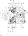
- the shaft bearing 12 has a bearing block 16 which has a semicircular recess 17 for receiving the shaft end 11 (FIG. 1). Below this recess 17 there are two further recesses 18 and 19, in which there are two rotating bodies 20 and 21, which are opposite each other with respect to a central plane of the shaft bearing 12. Each of these rotating bodies 20, 21 is rotatably mounted about a rotating body axis 53 parallel to the bearing axis 54. These two rotating body axes 53 are arranged symmetrically to the central plane of the shaft bearing 12.
- the rotating body 20 is composed of three bearing shells 22, 23 and 24, which are integrated here into a single rotating body 20. These three bearing shells 22, 23 and 24 differ only in their nominal diameters 22a, 23a and 24a. This nominal diameter 22a, 23a and 24a corresponds to the diameter of the shaft end 11 on the workpiece 10.
- the bearing shell 22 In the position of the rotating body 20 shown, the bearing shell 22 is in its working position, and the two bearing shells 23 and 24 are in the rest position. This means that in the position of the two rotating bodies 20 and 21 shown, only one workpiece 10 with a shaft end 11 can be inserted into the shaft bearing 12, which has a shaft diameter that corresponds to the nominal diameter 22a.
- one of the other two bearing shells 23 or 24 can be brought into the working position, so that a workpiece 10 with a different shaft diameter can be used. Thanks to the three bearing shells 22, 23 and 24, it is thus possible to use shaft ends 11 of three different diameters in the shaft bearing 12, as can be seen from FIGS. 3, 4 and 5.
- FIG. 3 An actuating device 52 for rotating the rotating bodies 20, 21 is described below.
- a pinion 25 or 26 is attached to each rotating body 20 and 21 (FIG. 2).
- Each of these pinions 25 and 26 is in engagement with a rack 27, 28.
- the two racks 27, 28 are connected to one another via a screw 29 and lock nuts 30.
- This screw connection 29, 30 between the two toothed racks 27, 28 enables the position of the two rotating bodies 20 and 21 (FIG. 2) to be matched exactly to one another so that they are correctly positioned on the shaft end 11 (FIG. 1) of the workpiece 10 to be supported issue.
- a piston rod 31 is screwed onto the rack 28, which connects the two racks 27, 28 with an actuating piston 32.
- This actuating piston 32 is located in a first displaceable cylinder 33.
- This cylinder is closed by two covers 34 and 35. With the one cover 35, a second sleeve-shaped piston rod 36 is formed in one piece.
- a second piston 37 is fastened, which is located in a second, stationary cylinder 38.
- the second cylinder 38 is fastened to the bearing block 16 via a connecting piece 39.
- a bore 47, 48, 49 leads from a central bore 46 in each rotating body 20, 21 to the three bearing shells 22, 23 and 24.
- This central bore 46 and these three further bores 47, 48, 49 can the bearing shell 22, 23 or 24 lubricating liquid in each working position are supplied.
- hard metal inserts 50 are provided in each bearing shell 22, 23 and 24, which serve to protect the bearing surfaces by eliminating minor unevenness in the surface of the Smooth shaft end 11.
- the support device 15 described below is only required for heavy workpieces 10.
- the support device 15 has a rod 40 that can be raised and lowered.
- a fork 41 in which a roller 42 is supported, on which the shaft end 11 of the workpiece 10 can be supported.
- a piston 43 which is mounted in a cylinder 44 so as to be displaceable by the stroke 45.
- the cylinder 44 is inserted in the bearing block 16. 2, this piston 43 is shown in its lowest position.
- the piston 43 is raised by a pressure medium, so that the roller 42 is also raised via the rod 40 and pressed against the shaft end 11 of the workpiece 10, so that the shaft bearing 12 is relieved.
- the shaft end 11 is still guided through the bearing shells 22, 23 or 24, which, however, are not loaded with the full weight of the workpiece 10.
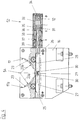
- the bearing shells 22 of the two rotating bodies 20 and 21 are in the working position.
- the nominal diameter 22a corresponds exactly to the diameter 17a of the recess 17, as can be seen in particular from FIG. 2. Therefore, the bearing shells 22 of the rotating bodies 20 and 21 do not protrude in FIG. 3.
- the two racks 27 and 28 are in their right end position, as can be seen from FIG. 3.
- the two pistons 32 and 37 are in their right end position in the cylinders 33 and 38.
- the displaceable cylinder 33 is also in its right end position.
- the two pressure lines A and C are under pressure
- the two pressure lines B and D are under a lower pressure or are depressurized.
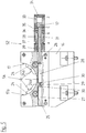
- the bearing shells 23 of the two rotating bodies 20 and 21 are in the working position.
- the nominal diameter 23a is smaller than the diameter 17a of the recess 17, so that the two bearing shells 23 of the two rotating bodies 20 and 21 protrude in FIG. 4.
- the two racks 27 and 28 are in their central position, as can be seen from FIG. 4.
- the first piston 32 has remained in its right end position, the second piston 37 has been displaced into its left end position, so that the displaceable cylinder 33 has also reached its left end position.
- the two lines B and C are under pressure and the other two pressure lines A and D are under a lower pressure or are depressurized.
- the bearing shells 24 of the two rotating bodies 20 and 21 are in the working position.
- the nominal diameter 24a is even smaller than the diameter 17a of the recess 17, so that the two bearing shells 24 of the two rotating bodies 20 and 21 in FIG. 5 protrude slightly more than the bearing shells 23 in FIG. 4.
- the two rotating bodies 20 and 21, the two racks 27 and 28 are in their left end position, as can be seen from FIG. 5.
- the two pistons 32 and 37 are in their left end position in the cylinders 33 and 38.
- the displaceable cylinder 33 is also in its left end position.
- the two pressure lines B and D are under pressure and the two pressure lines A and C are under a smaller one Pressure or are depressurized.
- the bearing shells 24 of the two rotating bodies 20 and 21 are in the working position, so that the diameter of the shaft end 11 of the workpiece 10 must correspond to the nominal diameter 24a of these bearing shells 24. Accordingly, the piston 43 of the support device 15 has also been raised by the stroke 45 (see FIG. 2).
- the rotating bodies 20, 21 shown in FIG. 6 are mirror images. So that e.g. instead of the two bearing shells 24, the two bearing shells 22 come into the working position, the two rotating bodies 20, 21 must be rotated in the opposite sense, i.e. the rotating body 20 is rotated clockwise and the rotating body 21 is rotated counterclockwise.
- the actuating device 52 would therefore have to be designed differently accordingly.
- the actuator 52 could e.g. only be connected to one of the rotating bodies 20, 21 and the rotation of this one rotating body is transmitted in opposite directions to the other rotating body via an idler gear.
- the pressure lines A, B, C, D of the actuating device 52 are preferably kept depressurized so that the bearing shells 22, 23, 24 can center themselves under the weight of the workpiece 10.
- shaft bearing according to the invention is not only suitable for processing machines for gravure cylinders, but also for other types of processing machines in which workpieces with different Shaft diameters must be rotatably supported.
Landscapes
- Engineering & Computer Science (AREA)
- General Engineering & Computer Science (AREA)
- Mechanical Engineering (AREA)
- Sliding-Contact Bearings (AREA)
Applications Claiming Priority (2)
| Application Number | Priority Date | Filing Date | Title |
|---|---|---|---|
| CH216392 | 1992-07-09 | ||
| CH2163/92 | 1992-07-09 |
Publications (2)
| Publication Number | Publication Date |
|---|---|
| EP0579969A1 true EP0579969A1 (fr) | 1994-01-26 |
| EP0579969B1 EP0579969B1 (fr) | 1996-01-10 |
Family
ID=4227353
Family Applications (1)
| Application Number | Title | Priority Date | Filing Date |
|---|---|---|---|
| EP93109985A Expired - Lifetime EP0579969B1 (fr) | 1992-07-09 | 1993-06-23 | Palier d'arbre pour machine d'usinage |
Country Status (2)
| Country | Link |
|---|---|
| EP (1) | EP0579969B1 (fr) |
| DE (1) | DE59301391D1 (fr) |
Cited By (1)
| Publication number | Priority date | Publication date | Assignee | Title |
|---|---|---|---|---|
| DE102014106334A1 (de) * | 2014-05-07 | 2015-11-12 | Schenck Rotec Gmbh | Vorrichtung zur drehbaren Lagerung von Werkstücken, insbesondere Kurbelwellen |
Citations (1)
| Publication number | Priority date | Publication date | Assignee | Title |
|---|---|---|---|---|
| DE8432100U1 (de) * | 1984-11-02 | 1988-01-14 | Dr.-Ing. Rudolf Hell Gmbh, 2300 Kiel | Vorrichtung zum Abstützen von Spindeln |
-
1993
- 1993-06-23 DE DE59301391T patent/DE59301391D1/de not_active Expired - Fee Related
- 1993-06-23 EP EP93109985A patent/EP0579969B1/fr not_active Expired - Lifetime
Patent Citations (1)
| Publication number | Priority date | Publication date | Assignee | Title |
|---|---|---|---|---|
| DE8432100U1 (de) * | 1984-11-02 | 1988-01-14 | Dr.-Ing. Rudolf Hell Gmbh, 2300 Kiel | Vorrichtung zum Abstützen von Spindeln |
Cited By (4)
| Publication number | Priority date | Publication date | Assignee | Title |
|---|---|---|---|---|
| DE102014106334A1 (de) * | 2014-05-07 | 2015-11-12 | Schenck Rotec Gmbh | Vorrichtung zur drehbaren Lagerung von Werkstücken, insbesondere Kurbelwellen |
| WO2015169823A1 (fr) | 2014-05-07 | 2015-11-12 | Schenck Rotec Gmbh | Dispositif pour supporter à rotation des pièces, notamment des vilebrequins |
| DE102014106334B4 (de) * | 2014-05-07 | 2015-11-26 | Schenck Rotec Gmbh | Vorrichtung zur drehbaren Lagerung von Werkstücken, insbesondere Kurbelwellen |
| US10295428B2 (en) | 2014-05-07 | 2019-05-21 | Schenck Rotec Gmbh | Device for rotatable mounting of work pieces, in particular crankshafts |
Also Published As
| Publication number | Publication date |
|---|---|
| EP0579969B1 (fr) | 1996-01-10 |
| DE59301391D1 (de) | 1996-02-22 |
Similar Documents
| Publication | Publication Date | Title |
|---|---|---|
| DE69617920T2 (de) | Methode und gerät zum ausrichten eines zylinders in einer graviermaschine | |
| DE69926266T2 (de) | Flexographische Mehrfarben-Rotationsdruckmaschine mit einer Haupttrommel und getrennten, unabhängigen Farbdruckeinheiten | |
| EP0353376A1 (fr) | Outil de brunissage | |
| DE4130811C2 (de) | Presse mit verstellbarem Hub | |
| EP0017660A1 (fr) | Presse hydraulique | |
| DE3108780C2 (de) | Kurbelwellenfest- bzw. Glattwalzmaschine | |
| DE4132976C2 (de) | Vorrichtung an einer Presse zum Verstellen der Hübe eines Arbeitsstößels und einer Gegenschwingmasse | |
| DE4320668A1 (de) | Walzenmühle | |
| DE2754357C2 (fr) | ||
| DE2144711A1 (de) | Hydraulikvorrichtung zum Festklemmen und Lösen von Lagern | |
| EP3283243B1 (fr) | Dispositif à cylindres annulaires comportant des paliers à roulement axialement fixes | |
| DE3126561C2 (de) | Lagerung für Druckwerkszylinder oder dergleichen mit einstellbarem Seitenregister | |
| EP0453788A1 (fr) | Dispositif d'enclenchement, de déclenchement et de réglage des rouleaux d'encrage | |
| AT392661B (de) | Presswalze, deren durchbiegung einstellbar ist | |
| DE2340125A1 (de) | Maschine zum profilwalzen von ringen | |
| EP1428612A1 (fr) | Dispositif et procédé de positionnement angulaire de pièces excentriques telles que des villebrequins, par l'intermédiaire de mâchoires montées sur une lunette de centrage | |
| EP0579969B1 (fr) | Palier d'arbre pour machine d'usinage | |
| DE10242009B4 (de) | Druckmaschine, vorzugsweise Flexodruckmaschine | |
| DE19531104C2 (de) | Drehmaschinen-Spannfutter mit verstellbarer Exzentrizität | |
| EP1628828B1 (fr) | Unite de blocage de mandrin concue pour les mandrins de rouleau imprimeur d'une presse rotative | |
| DE1939863A1 (de) | Vorrichtung zum Daempfen von Erschuetterungen bei Werkzeugmaschinen | |
| DE2116233A1 (de) | Preßglattmaschine | |
| DE3132646A1 (de) | Walzvorrichtung und verfahren zum walzen stangenfoermigen materials | |
| EP0123976B1 (fr) | Chariot réglable pour cylindre à imprimer | |
| DE2106478A1 (de) | Vorrichtung zur Verringerung bzw. Beseitigung von Vibrationen eines stabförmigen Materials bei Drehung in einem Vorschubmechanismus |
Legal Events
| Date | Code | Title | Description |
|---|---|---|---|
| PUAI | Public reference made under article 153(3) epc to a published international application that has entered the european phase |
Free format text: ORIGINAL CODE: 0009012 |
|
| AK | Designated contracting states |
Kind code of ref document: A1 Designated state(s): CH DE FR IT LI |
|
| 17P | Request for examination filed |
Effective date: 19940630 |
|
| 17Q | First examination report despatched |
Effective date: 19950426 |
|
| GRAA | (expected) grant |
Free format text: ORIGINAL CODE: 0009210 |
|
| AK | Designated contracting states |
Kind code of ref document: B1 Designated state(s): CH DE FR IT LI |
|
| ITF | It: translation for a ep patent filed | ||
| REF | Corresponds to: |
Ref document number: 59301391 Country of ref document: DE Date of ref document: 19960222 |
|
| REG | Reference to a national code |
Ref country code: CH Ref legal event code: NV Representative=s name: SCHAAD, BALASS & PARTNER AG |
|
| ET | Fr: translation filed | ||
| PGFP | Annual fee paid to national office [announced via postgrant information from national office to epo] |
Ref country code: CH Payment date: 19960626 Year of fee payment: 4 |
|
| PLBE | No opposition filed within time limit |
Free format text: ORIGINAL CODE: 0009261 |
|
| STAA | Information on the status of an ep patent application or granted ep patent |
Free format text: STATUS: NO OPPOSITION FILED WITHIN TIME LIMIT |
|
| 26N | No opposition filed | ||
| PG25 | Lapsed in a contracting state [announced via postgrant information from national office to epo] |
Ref country code: LI Free format text: LAPSE BECAUSE OF NON-PAYMENT OF DUE FEES Effective date: 19970630 Ref country code: CH Free format text: LAPSE BECAUSE OF NON-PAYMENT OF DUE FEES Effective date: 19970630 |
|
| REG | Reference to a national code |
Ref country code: CH Ref legal event code: PL |
|
| PGFP | Annual fee paid to national office [announced via postgrant information from national office to epo] |
Ref country code: DE Payment date: 20020624 Year of fee payment: 10 |
|
| PGFP | Annual fee paid to national office [announced via postgrant information from national office to epo] |
Ref country code: FR Payment date: 20020626 Year of fee payment: 10 |
|
| PG25 | Lapsed in a contracting state [announced via postgrant information from national office to epo] |
Ref country code: DE Free format text: LAPSE BECAUSE OF NON-PAYMENT OF DUE FEES Effective date: 20040101 |
|
| PG25 | Lapsed in a contracting state [announced via postgrant information from national office to epo] |
Ref country code: FR Free format text: LAPSE BECAUSE OF NON-PAYMENT OF DUE FEES Effective date: 20040227 |
|
| REG | Reference to a national code |
Ref country code: FR Ref legal event code: ST |
|
| PG25 | Lapsed in a contracting state [announced via postgrant information from national office to epo] |
Ref country code: IT Free format text: LAPSE BECAUSE OF NON-PAYMENT OF DUE FEES;WARNING: LAPSES OF ITALIAN PATENTS WITH EFFECTIVE DATE BEFORE 2007 MAY HAVE OCCURRED AT ANY TIME BEFORE 2007. THE CORRECT EFFECTIVE DATE MAY BE DIFFERENT FROM THE ONE RECORDED. Effective date: 20050623 |