EP0453788A1 - Dispositif d'enclenchement, de déclenchement et de réglage des rouleaux d'encrage - Google Patents
Dispositif d'enclenchement, de déclenchement et de réglage des rouleaux d'encrage Download PDFInfo
- Publication number
- EP0453788A1 EP0453788A1 EP91104692A EP91104692A EP0453788A1 EP 0453788 A1 EP0453788 A1 EP 0453788A1 EP 91104692 A EP91104692 A EP 91104692A EP 91104692 A EP91104692 A EP 91104692A EP 0453788 A1 EP0453788 A1 EP 0453788A1
- Authority
- EP
- European Patent Office
- Prior art keywords
- cams
- housing
- rollers
- cam
- guide
- Prior art date
- Legal status (The legal status is an assumption and is not a legal conclusion. Google has not performed a legal analysis and makes no representation as to the accuracy of the status listed.)
- Granted
Links
- 238000007645 offset printing Methods 0.000 claims abstract description 4
- 230000008878 coupling Effects 0.000 claims description 12
- 238000010168 coupling process Methods 0.000 claims description 12
- 238000005859 coupling reaction Methods 0.000 claims description 12
- 238000007639 printing Methods 0.000 abstract description 7
- 238000010276 construction Methods 0.000 abstract 1
- 238000009434 installation Methods 0.000 description 2
- 238000009826 distribution Methods 0.000 description 1
- 238000005553 drilling Methods 0.000 description 1
- 238000005461 lubrication Methods 0.000 description 1
- 238000004519 manufacturing process Methods 0.000 description 1
- 238000000034 method Methods 0.000 description 1
Images


Classifications
-
- B—PERFORMING OPERATIONS; TRANSPORTING
- B41—PRINTING; LINING MACHINES; TYPEWRITERS; STAMPS
- B41F—PRINTING MACHINES OR PRESSES
- B41F31/00—Inking arrangements or devices
- B41F31/30—Arrangements for tripping, lifting, adjusting, or removing inking rollers; Supports, bearings, or forks therefor
- B41F31/301—Devices for tripping and adjusting form rollers
Definitions
- the invention relates to a device for switching on, off and setting of application rollers in a printing press according to the preamble of patent claim 1.
- Such a device is described in FR-PS 1 207 883.
- the inking rollers can be swiveled in pairs arranged around friction rollers of the inking unit. They are supported against spring elements that maintain the end position of the inking rollers in the on and off positions. The positions are set individually using wedge elements, which can be moved from the outside using adjusting spindles between the roller bearings and their respective supports.
- the inking rollers are supported on an on and off curve, which is located centrally on the bearing of the forme cylinder and can be rotated there.
- the starting and stopping curve has a curve for each inking roller with a low point for the starting position and a high point for the stopping position.
- the device has a wide range of adjustment options for the inking rollers, both towards the distribution rollers and towards the forme cylinder.
- the inking rollers can only be adjusted individually using controls that end outside the machine wall. The controls reach through the gearbox of the printing press.
- the installation space is very large due to the use of support elements and the execution of the turn-on and turn-off curve as a ring that surrounds the bearing of the forme cylinder. Overall, the arrangement is a hindrance to the technical implementation of constructive measures in the area of the inking rollers and requires high assembly and adjustment effort.
- the aim of the invention is to improve these structural conditions.
- control cams are arranged on individual cams. So they can be shifted against each other and edited separately.
- the subclaims show further advantageous configurations of the device.
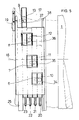
- FIG. 1 the device is shown overall in side view.
- a form cylinder 1 is assigned application rollers 2, 3, 4, 5. Their roller bearings are supported with the help of cam rollers 6, 7, 8, 9 on cams 10, 11, 12, 13 of the device.
- the application rollers 3, 4, 5 are assigned to the friction rollers 14, 15 and swivel around and towards them as they are turned on and off.
- the cams 10, 11, 12, 13 are mounted within a housing 16, which is supported in an arc on the outside of a central collar 17 on an eccentric bearing 17 of the forme cylinder 1. At one end of this housing 16, a tab 19 is articulated, which connects the housing 16 to an actuator 18 for turning the applicator rollers 2, 3, 4, 5 on and off.
- adjusting spindles 20, 21, 22, 23 are attached to the cam disks 10, 11, 12, 13, which are supported on a coupling element 26 connected to the housing 16, which in turn has an adjusting spindle 24 by one on the housing 16 subsequent extension 16.1 is movable relative to the housing 16 itself.
- the cam rollers 6, 7, 8, 9 on the applicator roller bearings each pass through openings in the top of the housing 16
- the individual cams 10, 11, 12, 13 are adjustable within the housing 16, on the other hand, the cams 10, 11, 12, 13 are adjustable together relative to the housing 16 and the entire housing 16 can be moved back and forth with the aid of the actuator 18 be pivoted, which moves coaxially to the forme cylinder 1 on the periphery of the collar 17 on the eccentric bearing.
- the housing 16 has on one side an opening 41, which is production-related and is used for threading the four cams 10, 11, 12, 13. These are packed side by side. All cams 10, 11, 12, 13 have basically the same structure, which will be explained in more detail later. Each cam 10, 11, 12, 13 is provided for only one applicator roller 2, 3, 4, 5. In addition, there is an additional guide segment 25, with which the coupling element 26 of the individual cams 10, 11, 12, 13 is firmly connected. By moving this guide segment 25, all cams 10, 11, 12, 13 can be moved together. The illustration also shows that the cam roller 6 is seated on the cam disc 10 and supports the applicator roller 2 via an axis.
- a cam 10 is shown in detail.
- the cam disc 10 contains on the inside and outside guide surfaces 27, 28 with which it is guided inside the housing 16.
- curves 29, 30 which serve for starting and stopping as well as adjusting the application rollers.
- the high point indicates as the parking cam 30 the parking position of the application rollers.
- the pitch curve 29 is designed as a linear curve and extends over a larger area, so that setting options for the application rollers 2, 3, 4, 5 are also available. All cams 10, 11, 12, 13 have the same slope of this pitch curve, so at common employment changes a same change is generated for all application rollers 2, 3, 4, 5.
- a bore 31 is provided in which the adjusting spindle 20 is mounted.
- the coupling of the cam disks 10, 11, 12, 13 is shown in FIG. 4, the coupling element 26, which is arranged on the guide segment 25, being shown again here.
- the coupling element 26 is firmly pinned there and has recesses into which the adjusting spindles 20, 21, 22, 23 are hung. These are in turn articulated on the cams 10, 11, 12, 13.
- the articulation should be as free of play as possible and can take place via coupling disks 39 rotatably mounted in the bore 31.
- a further pivotably mounted coupling disk 40 is provided on the guide segment 25, with which the adjusting spindle 24 is connected. This is in turn hinged to a pin 33 on the extension 16.1 of the housing 16.
- Coupling element 26, guide segment 25 and all cams 10, 11, 12, 13 can thus be displaced jointly by means of adjusting spindle 24 relative to extension 16.1 and thus also relative to housing 16.
- FIG. 1 A top view of the housing 16 is shown here. It is clear that the setting zones of the in the circumferential direction of the forme cylinder 1 and axially adjacent to each other different application rollers 10, 11, 12, 13 are arranged. This can be seen in recesses 34, 35, 36, 37, which are mounted in steps in the top of the housing 16. Through these recesses, the cam rollers 6, 7, 8, 9 of the applicator roller bearings grip for support on the cams 10, 11, 12, 13.
- the recesses 34, 35, 36, 37 are each wider than just one disc width. This allows the cam rollers 6, 7, 8, 9, which are shown in broken lines, with their axes to freely enter the recesses 34, 35, 36, 37 when the application rollers 2, 3, 4, 5 are turned on or set.
- the entire device can be preassembled outside the machine and is only to be placed inside the machine on the central collar 17 of the plate cylinder bearing. It is held there in the axial direction by retaining rings 38 and loaded in the radial direction by the springing of the applicator roller bearings. In the circumferential direction, the entire device is held by the actuator 18 and the tab 19, which only has to be attached to the housing 16 during installation.
Landscapes
- Inking, Control Or Cleaning Of Printing Machines (AREA)
- Rolls And Other Rotary Bodies (AREA)
Priority Applications (1)
| Application Number | Priority Date | Filing Date | Title |
|---|---|---|---|
| AT91104692T ATE98563T1 (de) | 1990-04-24 | 1991-03-26 | Vorrichtung zum an-, ab- und einstellen von farbauftragwalzen. |
Applications Claiming Priority (2)
| Application Number | Priority Date | Filing Date | Title |
|---|---|---|---|
| DE4012965A DE4012965C1 (de) | 1990-04-24 | 1990-04-24 | Vorrichtung zum An-, Ab- und Einstellen von Auftragwalzen |
| DE4012965 | 1990-04-24 |
Publications (2)
| Publication Number | Publication Date |
|---|---|
| EP0453788A1 true EP0453788A1 (fr) | 1991-10-30 |
| EP0453788B1 EP0453788B1 (fr) | 1993-12-15 |
Family
ID=6404938
Family Applications (1)
| Application Number | Title | Priority Date | Filing Date |
|---|---|---|---|
| EP91104692A Expired - Lifetime EP0453788B1 (fr) | 1990-04-24 | 1991-03-26 | Dispositif d'enclenchement, de déclenchement et de réglage des rouleaux d'encrage |
Country Status (6)
| Country | Link |
|---|---|
| US (1) | US5101723A (fr) |
| EP (1) | EP0453788B1 (fr) |
| JP (1) | JPH07110539B2 (fr) |
| AT (1) | ATE98563T1 (fr) |
| DE (2) | DE4012965C1 (fr) |
| ES (1) | ES2047962T3 (fr) |
Families Citing this family (12)
| Publication number | Priority date | Publication date | Assignee | Title |
|---|---|---|---|---|
| DE4112158C2 (de) * | 1991-04-13 | 1994-11-10 | Roland Man Druckmasch | Vorrichtung zur Verstellung des axialen Hubes einer Walze einer Druckmaschine |
| JPH08216376A (ja) * | 1995-02-09 | 1996-08-27 | Nagano Japan Radio Co | 印刷機の処理ローラ用リリース装置 |
| DE19515726A1 (de) * | 1995-05-03 | 1996-11-07 | Roland Man Druckmasch | Vorrichtung zum An- und Abstellen von Walzen |
| US6024017A (en) * | 1997-09-26 | 2000-02-15 | Dainippon Screen Mfg. Co., Ltd. | Printing apparatus |
| DE29901697U1 (de) * | 1999-02-01 | 2000-07-13 | Heidelberger Druckmaschinen Ag, 69115 Heidelberg | Farbwerk in einer Druckmaschine |
| DE10023605A1 (de) * | 2000-05-15 | 2002-06-27 | Roland Man Druckmasch | Vorrichtung zum Einstellen einer Auftragwalze am Plattenzylinder einer Druckmaschine |
| DE10152020C2 (de) * | 2001-03-20 | 2003-05-08 | Koenig & Bauer Ag | Vorrichtung zum Einstellen des Anpressdrucks einer verstellbar gelagerten Walze |
| DE10113314C2 (de) * | 2001-03-20 | 2003-10-30 | Koenig & Bauer Ag | Fixiereinrichtung |
| JP4068063B2 (ja) * | 2001-12-06 | 2008-03-26 | ケーニツヒ ウント バウエル アクチエンゲゼルシヤフト | 印刷機のローラを調節するための装置 |
| DE102004022772B4 (de) * | 2004-05-05 | 2008-07-24 | Koenig & Bauer Aktiengesellschaft | Verfahren und Vorrichtung zum An- und Abstellen von Farbwalzen in Rotations-Druckmaschinen |
| DE102004022701B4 (de) * | 2004-05-05 | 2015-09-17 | Koenig & Bauer Aktiengesellschaft | Verfahren zum Betreiben eines Farbwerks einer Rotations-Druckmaschine |
| DE102006046151A1 (de) * | 2006-09-28 | 2008-04-03 | Koenig & Bauer Aktiengesellschaft | Druckmaschine mit mehreren, an einen Plattenzylinder an- und abstellbaren Auftragwalzen |
Citations (3)
| Publication number | Priority date | Publication date | Assignee | Title |
|---|---|---|---|---|
| FR1207883A (fr) * | 1958-07-22 | 1960-02-19 | Color Metal A G | Perfectionnements apportés aux presses à imprimer |
| EP0087625A1 (fr) * | 1982-03-03 | 1983-09-07 | M.A.N.-ROLAND Druckmaschinen Aktiengesellschaft | Dispositif pour l'application des rouleaux toucheurs sur le cylindre porte-plaque des machines d'impression et pour l'enlèvement et le réglage de ces rouleaux |
| DD264654A1 (de) * | 1987-10-29 | 1989-02-08 | Polygraph Leipzig | Vorrichtung zum an- und abstellen der farbauftragwalzen |
Family Cites Families (7)
| Publication number | Priority date | Publication date | Assignee | Title |
|---|---|---|---|---|
| US3538849A (en) * | 1968-01-24 | 1970-11-10 | Miehle Goss Dexter Inc | Oscillator ink roller mounting and control means |
| US3691956A (en) * | 1970-11-20 | 1972-09-19 | North American Rockwell | Flat adjusting and throw-off arrangement for form roller in printing press |
| JPS61105144U (fr) * | 1984-12-18 | 1986-07-04 | ||
| JP2563171B2 (ja) * | 1987-04-22 | 1996-12-11 | 株式会社小森コーポレーション | 輪転印刷機のインキ装置 |
| JPS63264335A (ja) * | 1987-04-22 | 1988-11-01 | Kanegafuchi Chem Ind Co Ltd | 電子レンジ調理用容器成形用積層発泡シ−ト |
| JP2563172B2 (ja) * | 1987-04-22 | 1996-12-11 | 株式会社小森コーポレーション | 輪転印刷機のインキ装置 |
| JPH01125635U (fr) * | 1988-02-09 | 1989-08-28 |
-
1990
- 1990-04-24 DE DE4012965A patent/DE4012965C1/de not_active Expired - Lifetime
-
1991
- 1991-03-26 DE DE91104692T patent/DE59100711D1/de not_active Expired - Fee Related
- 1991-03-26 AT AT91104692T patent/ATE98563T1/de not_active IP Right Cessation
- 1991-03-26 EP EP91104692A patent/EP0453788B1/fr not_active Expired - Lifetime
- 1991-03-26 ES ES91104692T patent/ES2047962T3/es not_active Expired - Lifetime
- 1991-04-23 US US07/690,061 patent/US5101723A/en not_active Expired - Fee Related
- 1991-04-23 JP JP3092071A patent/JPH07110539B2/ja not_active Expired - Fee Related
Patent Citations (3)
| Publication number | Priority date | Publication date | Assignee | Title |
|---|---|---|---|---|
| FR1207883A (fr) * | 1958-07-22 | 1960-02-19 | Color Metal A G | Perfectionnements apportés aux presses à imprimer |
| EP0087625A1 (fr) * | 1982-03-03 | 1983-09-07 | M.A.N.-ROLAND Druckmaschinen Aktiengesellschaft | Dispositif pour l'application des rouleaux toucheurs sur le cylindre porte-plaque des machines d'impression et pour l'enlèvement et le réglage de ces rouleaux |
| DD264654A1 (de) * | 1987-10-29 | 1989-02-08 | Polygraph Leipzig | Vorrichtung zum an- und abstellen der farbauftragwalzen |
Also Published As
| Publication number | Publication date |
|---|---|
| DE4012965C1 (de) | 1991-02-07 |
| EP0453788B1 (fr) | 1993-12-15 |
| US5101723A (en) | 1992-04-07 |
| JPH05309826A (ja) | 1993-11-22 |
| ATE98563T1 (de) | 1994-01-15 |
| JPH07110539B2 (ja) | 1995-11-29 |
| DE59100711D1 (de) | 1994-01-27 |
| ES2047962T3 (es) | 1994-03-01 |
Similar Documents
| Publication | Publication Date | Title |
|---|---|---|
| EP3332100B1 (fr) | Système de distribution pour un moteur à combustion interne | |
| EP0812681A1 (fr) | Machine d'impression | |
| EP1731460A1 (fr) | Corps cylindrique d'une machine de traitement de matériau de bande imprimée | |
| EP0769373B1 (fr) | Dispositif de changement des manchons de cylindres d'imprimerie dans les machines à imprimer | |
| EP0453788B1 (fr) | Dispositif d'enclenchement, de déclenchement et de réglage des rouleaux d'encrage | |
| DE3207622C2 (de) | Vorrichtung zum An-, Ab- und Einstellen von Auftragwalzen am Plattenzylinder von Druckmaschinen | |
| EP0239830A2 (fr) | Dispositif de réglage de la position angulaire relative entre une roue dentée et une couronne dentée coaxiale | |
| EP0549884B1 (fr) | Dispositif pour la séparation d'un train d'engrenage | |
| EP1383701B1 (fr) | Cylindre d'un appareil de pliage | |
| EP1310360B1 (fr) | Machine d'impression flexographique avec des cylindres de transfert d'encre applicables de façon manuelle et automatique | |
| DE102020205721A1 (de) | Ladeteller für Federendenschleifmaschine und Federendenschleifmaschine | |
| EP3332099B1 (fr) | Distribution pour un moteur à combustion interne | |
| DE9116367U1 (de) | Zylinder für die Papierführung an Bogenrotationsdruckmaschinen | |
| EP0683043B1 (fr) | Cylindre d'impression d'une machine d'impression rotative | |
| EP0442265A1 (fr) | Accouplement de serrage pour un composant de réglage déplaçable axialement pour le changement de rotation de la griffe sur une rotative typographique | |
| EP0741024B1 (fr) | Dispositif pour serrer et séparer des rouleaux | |
| DE3317746C2 (de) | Druckwerk und Verfahren zum Drucken | |
| EP0172412A2 (fr) | Cylindre de transfert de feuilles dans les rotatives d'impression de feuilles | |
| EP0243737A2 (fr) | Cylindre de retournement pour machine rotative à imprimer des feuilles | |
| EP0155561B1 (fr) | Dispositif pour l'impression sélective sur une face ou à retiration dans le tambour d'accumulation d'une machine à imprimer offset pour feuilles | |
| EP2057017B1 (fr) | Élément d'impression d'une machine d'héliogravure | |
| EP1984181B1 (fr) | Couplage de cylindre gravé | |
| EP0771648A1 (fr) | Dispositif de rattrapage de jeu dans une machine d'impression | |
| DE3800658A1 (de) | Vorrichtung zum auftragen von farbe und/oder feuchtmittel auf eine druckform | |
| EP4516509B1 (fr) | Dispositif et procédé pour supporter un cylindre d'impression |
Legal Events
| Date | Code | Title | Description |
|---|---|---|---|
| PUAI | Public reference made under article 153(3) epc to a published international application that has entered the european phase |
Free format text: ORIGINAL CODE: 0009012 |
|
| 17P | Request for examination filed |
Effective date: 19910826 |
|
| AK | Designated contracting states |
Kind code of ref document: A1 Designated state(s): AT BE CH DE ES FR GB IT LI NL SE |
|
| 17Q | First examination report despatched |
Effective date: 19930521 |
|
| ITF | It: translation for a ep patent filed | ||
| GRAA | (expected) grant |
Free format text: ORIGINAL CODE: 0009210 |
|
| AK | Designated contracting states |
Kind code of ref document: B1 Designated state(s): AT BE CH DE ES FR GB IT LI NL SE |
|
| REF | Corresponds to: |
Ref document number: 98563 Country of ref document: AT Date of ref document: 19940115 Kind code of ref document: T |
|
| ET | Fr: translation filed | ||
| REF | Corresponds to: |
Ref document number: 59100711 Country of ref document: DE Date of ref document: 19940127 |
|
| GBT | Gb: translation of ep patent filed (gb section 77(6)(a)/1977) |
Effective date: 19940110 |
|
| REG | Reference to a national code |
Ref country code: ES Ref legal event code: FG2A Ref document number: 2047962 Country of ref document: ES Kind code of ref document: T3 |
|
| PLBE | No opposition filed within time limit |
Free format text: ORIGINAL CODE: 0009261 |
|
| STAA | Information on the status of an ep patent application or granted ep patent |
Free format text: STATUS: NO OPPOSITION FILED WITHIN TIME LIMIT |
|
| 26N | No opposition filed | ||
| EAL | Se: european patent in force in sweden |
Ref document number: 91104692.8 |
|
| PGFP | Annual fee paid to national office [announced via postgrant information from national office to epo] |
Ref country code: FR Payment date: 19980213 Year of fee payment: 8 |
|
| PGFP | Annual fee paid to national office [announced via postgrant information from national office to epo] |
Ref country code: SE Payment date: 19980219 Year of fee payment: 8 |
|
| PGFP | Annual fee paid to national office [announced via postgrant information from national office to epo] |
Ref country code: AT Payment date: 19980223 Year of fee payment: 8 |
|
| PGFP | Annual fee paid to national office [announced via postgrant information from national office to epo] |
Ref country code: CH Payment date: 19980225 Year of fee payment: 8 |
|
| PGFP | Annual fee paid to national office [announced via postgrant information from national office to epo] |
Ref country code: NL Payment date: 19980228 Year of fee payment: 8 |
|
| PGFP | Annual fee paid to national office [announced via postgrant information from national office to epo] |
Ref country code: ES Payment date: 19980316 Year of fee payment: 8 |
|
| PGFP | Annual fee paid to national office [announced via postgrant information from national office to epo] |
Ref country code: BE Payment date: 19980320 Year of fee payment: 8 |
|
| PG25 | Lapsed in a contracting state [announced via postgrant information from national office to epo] |
Ref country code: AT Free format text: LAPSE BECAUSE OF NON-PAYMENT OF DUE FEES Effective date: 19990326 |
|
| PG25 | Lapsed in a contracting state [announced via postgrant information from national office to epo] |
Ref country code: ES Free format text: THE PATENT HAS BEEN ANNULLED BY A DECISION OF A NATIONAL AUTHORITY Effective date: 19990327 Ref country code: SE Free format text: LAPSE BECAUSE OF NON-PAYMENT OF DUE FEES Effective date: 19990327 |
|
| PG25 | Lapsed in a contracting state [announced via postgrant information from national office to epo] |
Ref country code: CH Free format text: LAPSE BECAUSE OF NON-PAYMENT OF DUE FEES Effective date: 19990331 Ref country code: BE Free format text: LAPSE BECAUSE OF NON-PAYMENT OF DUE FEES Effective date: 19990331 Ref country code: LI Free format text: LAPSE BECAUSE OF NON-PAYMENT OF DUE FEES Effective date: 19990331 |
|
| BERE | Be: lapsed |
Owner name: M.A.N.-ROLAND DRUCKMASCHINEN A.G. Effective date: 19990331 |
|
| PG25 | Lapsed in a contracting state [announced via postgrant information from national office to epo] |
Ref country code: NL Free format text: LAPSE BECAUSE OF NON-PAYMENT OF DUE FEES Effective date: 19991001 |
|
| EUG | Se: european patent has lapsed |
Ref document number: 91104692.8 |
|
| REG | Reference to a national code |
Ref country code: CH Ref legal event code: PL |
|
| PG25 | Lapsed in a contracting state [announced via postgrant information from national office to epo] |
Ref country code: FR Free format text: LAPSE BECAUSE OF NON-PAYMENT OF DUE FEES Effective date: 19991130 |
|
| NLV4 | Nl: lapsed or anulled due to non-payment of the annual fee |
Effective date: 19991001 |
|
| EUG | Se: european patent has lapsed |
Ref document number: 91104692.8 |
|
| REG | Reference to a national code |
Ref country code: FR Ref legal event code: ST |
|
| PGFP | Annual fee paid to national office [announced via postgrant information from national office to epo] |
Ref country code: GB Payment date: 20010214 Year of fee payment: 11 |
|
| REG | Reference to a national code |
Ref country code: ES Ref legal event code: FD2A Effective date: 20010604 |
|
| REG | Reference to a national code |
Ref country code: GB Ref legal event code: IF02 |
|
| PG25 | Lapsed in a contracting state [announced via postgrant information from national office to epo] |
Ref country code: GB Free format text: LAPSE BECAUSE OF NON-PAYMENT OF DUE FEES Effective date: 20020326 |
|
| GBPC | Gb: european patent ceased through non-payment of renewal fee |
Effective date: 20020326 |
|
| PG25 | Lapsed in a contracting state [announced via postgrant information from national office to epo] |
Ref country code: IT Free format text: LAPSE BECAUSE OF NON-PAYMENT OF DUE FEES;WARNING: LAPSES OF ITALIAN PATENTS WITH EFFECTIVE DATE BEFORE 2007 MAY HAVE OCCURRED AT ANY TIME BEFORE 2007. THE CORRECT EFFECTIVE DATE MAY BE DIFFERENT FROM THE ONE RECORDED. Effective date: 20050326 |
|
| PGFP | Annual fee paid to national office [announced via postgrant information from national office to epo] |
Ref country code: DE Payment date: 20080321 Year of fee payment: 18 |
|
| PG25 | Lapsed in a contracting state [announced via postgrant information from national office to epo] |
Ref country code: DE Free format text: LAPSE BECAUSE OF NON-PAYMENT OF DUE FEES Effective date: 20091001 |