EP0580084A2 - Appareil et procédé pour la régénération de sable de fonderie - Google Patents
Appareil et procédé pour la régénération de sable de fonderie Download PDFInfo
- Publication number
- EP0580084A2 EP0580084A2 EP93111415A EP93111415A EP0580084A2 EP 0580084 A2 EP0580084 A2 EP 0580084A2 EP 93111415 A EP93111415 A EP 93111415A EP 93111415 A EP93111415 A EP 93111415A EP 0580084 A2 EP0580084 A2 EP 0580084A2
- Authority
- EP
- European Patent Office
- Prior art keywords
- regeneration
- dust
- regenerator
- stage
- air
- Prior art date
- Legal status (The legal status is an assumption and is not a legal conclusion. Google has not performed a legal analysis and makes no representation as to the accuracy of the status listed.)
- Withdrawn
Links
Images

Classifications
-
- B—PERFORMING OPERATIONS; TRANSPORTING
- B22—CASTING; POWDER METALLURGY
- B22C—FOUNDRY MOULDING
- B22C5/00—Machines or devices specially designed for dressing or handling the mould material so far as specially adapted for that purpose
- B22C5/10—Machines or devices specially designed for dressing or handling the mould material so far as specially adapted for that purpose by dust separating
-
- B—PERFORMING OPERATIONS; TRANSPORTING
- B22—CASTING; POWDER METALLURGY
- B22C—FOUNDRY MOULDING
- B22C5/00—Machines or devices specially designed for dressing or handling the mould material so far as specially adapted for that purpose
-
- Y—GENERAL TAGGING OF NEW TECHNOLOGICAL DEVELOPMENTS; GENERAL TAGGING OF CROSS-SECTIONAL TECHNOLOGIES SPANNING OVER SEVERAL SECTIONS OF THE IPC; TECHNICAL SUBJECTS COVERED BY FORMER USPC CROSS-REFERENCE ART COLLECTIONS [XRACs] AND DIGESTS
- Y10—TECHNICAL SUBJECTS COVERED BY FORMER USPC
- Y10S—TECHNICAL SUBJECTS COVERED BY FORMER USPC CROSS-REFERENCE ART COLLECTIONS [XRACs] AND DIGESTS
- Y10S241/00—Solid material comminution or disintegration
- Y10S241/10—Foundry sand treatment
Definitions
- the regeneration of foundry sand serves the purpose of separating the grains of the foundry sand from deliberately added foreign constituents such as bentonite, synthetic resin, coal, coke dust and other foreign substances and discharging them pneumatically from the material so that the regenerated material achieves new sand quality and also can be reused for cores. It is carried out in a regenerator, which is followed by a separator.
- the dust released in the regenerator is continuously or intermittently discharged by at least one air stream and transferred to the separator, where it is collected and separated. Depending on the design of the separator, all or all of the dust can be separated.
- Regenerators operating according to different principles are known, for example regenerators with rotary drums, which can be provided with internals such as whirlers or the like, or pneumatic or mechanical impact or centrifugal cleaners, fluid bed regenerators and regenerators as stationary sanding machines. Cyclone separators with downstream fine dust filters are mostly used as separators.
- the bentonite which can be contained in old sands in contents of up to 30% by mass and even more, and which also occurs in different states with different requirements, is particularly difficult to regenerate.
- Bentonite exists in the circulating plant sands of iron and steel foundries both as active bentonite necessary for molding sand binding and as fiber in the form of hard bentonite, which has lost its binding power due to the heat of the casting metal and is baked on the sand grains as a mostly hard shell is.
- the hard bentonite formation is often referred to as oolithization.
- Hard bentonite must be blasted off by impact or impact during the regeneration or be ground off by intensive grain-to-grain friction, the grinding treatment advantageously rounding off the grains of sand.
- Foundry sands differ due to changing quantity ratios of shaped and core sand and also because of the different thermal loads from batch to batch. But even when a batch is regenerated, the specific requirements change during the regeneration. Many failures in the regeneration of foundry sands result from the fact that the parameters set to mean values, such as machine running time, throughput speed, impact or grinding intensity and dedusting performance, remain unchanged. Inefficient operation and inadequate regeneration are the consequence with drastic effects on the core and casting quality. To make matters worse, the design of today's machines is not designed and suitable to carry out the changes in the grinding and dedusting processes required at short notice individually and in a coordinated manner.
- the invention has for its object to provide a simple and economical method for regenerating foundry sand using regenerators in which the dust is discharged pneumatically.
- the object is achieved in that the dust density in the discharge air is continuously measured during the regeneration and the measured values are used as signals for regulating the regeneration process.
- the sensor or sensors of the measuring device are arranged immediately before or in the exhaust air line of the regenerator and measure the dust density in the air flowing to a separator and deliver their measured values continuously or intermittently to a control device.
- additional sensors for example for temperature or humidity measurement, can also be provided.
- the signals are processed accordingly by the control device, which is expediently equipped with a fuzzy processor, and the individual actuators of the regenerator are controlled. Actuators of the separator connected downstream of the regenerator and of a regenerate conveyor and / or of an old sand dosing unit connected upstream of the regenerator can also be controlled by these signals.
- the quality of the regrind is largely determined by the residual dust content, which should be as close to zero as possible. For this reason, the regeneration cycle in the method according to the invention is concluded with a period of fine dust removal during which the grinding effect is virtually switched off, so that no further dust can arise.
- the batch is only released and automatically discharged when the sensor signals almost dust-free exhaust air.
- Today's technology offers several options for measuring dust density, for example the use of light barriers with light sources and photocells, whereby the light beam weakened by the dust in the exhaust air flow takes over the control function for the regenerator. With a high dust load, the passage of light is greatly reduced, so that bypassing with reduced but proportional amounts of dust is recommended for the measuring section. Dust deposits on light windows, photocells and other sensor parts must be prevented by constant fresh air flushing. When changing the amount of dedusting air, care must be taken to adjust the measuring sensitivity, because this also changes the dust concentration in the exhaust air.
- Infrared, ultrasound, capacitance and conductivity measurements in the dust air flow offer further possibilities for determining the dust density. It can also be advantageous to use different measuring methods next to or in succession. At high dust densities, ultrasound measurement, at low ones, light transmission measurement can offer better sensitivity. Isotope or radio indicators can also be used to measure dust density. Since active bentonite still contains electrolyte, its content in the exhaust air stream can be determined using appropriate measuring methods.
- a high degree of regeneration is often not required for the entire circulating sand in the foundry. For example a sufficient degree of regeneration is already sufficient for wet cast sand or cold resin core sand than for PUR cold box or hot box core sands, which require higher sand purities. In practice, therefore, only partial regeneration is sought, up to a degree of purity required for the intended use.
- regenerator types with different characteristics are used for the individual types of sand and, if necessary, also interconnected to form multi-stage regeneration plants (Giesserei 76, 1989, No. 10/11, pp. 350-358).
- regenerates are therefore often under-regenerated and faulty. For safety reasons, the regenerates are also regenerated to a higher level of purity than required. This costs time and energy and unnecessarily increases the amount of waste.
- the dust density of the discharge air of at least one stage is measured according to the invention and the measured values are used as signals for regulating this stage, a previous and / or a subsequent stage.
- the dust density can be measured in each stage and the measured values can be used to regulate the respective regeneration stage and to transfer the foundry sand from one stage to the next stage.
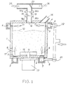
- the regenerator shown schematically in FIG. 1 has a container 1 with a base plate 2. Annular air chambers 3 and 4 are arranged around the side walls of the container 1 and under the base plate 2, into which feed lines 5, 6 for the dedusting air open.
- the lower air chamber 3 is connected to the interior of the container 1 via all-round nozzles 7.
- the upper air chamber 4 is connected to the interior of the container 1 via openings 9 above the fill level 10.
- the flow of the through-air indicated by arrow 8 takes up the ground foreign particles of the old sand and leads them through the exhaust air line 12 to a separator, not shown, which can consist of a cyclone separator with a fine filter.
- the cross-air flow indicated by arrow 11 also opens into line 12 and supports the dust discharge if the through-air flow 8 used to remove the foreign particles is too weak to transport coarser dust particles to the separation system.
- a speed-controllable motor 13 is mounted centrally, which drives a grinding rotor 15 via a shaft 14.
- the sand to be regenerated is introduced in a metered manner through a closable filling opening 16 up to the filling level 10 and emptied through the removal opening 17 after the end of the batch run.
- the dust-containing exhaust air 20 passes in the exhaust air line 12 the measuring points 18 and 19 of the sensors 18a, 18b and 19a, 19b, which are designed as a light barrier 18 and an ultrasonic measuring section 19.
- the light barrier 18 and the ultrasound measuring section 19 have different measuring sensitivities and can be switched in time or in sequence.
- in the exhaust air duct or further sensors can be provided on the container wall, which determine the temperature or humidity in the course of the process or control the deflection clap 23.
- the signals from the sensors are processed according to the unsharp logic method in an adaptive computer.
- it is equipped with a microprocessor with an integrated fuzzy unit, for example a chip of the type fuzzy-166 or higher.
- the through-air flow 8 coming from the air chamber 3 can be regulated via a valve 21 and the cross-air flow 11 coming from the air chamber 4 can be regulated via a valve 22, in such a way that the sum of the air flows 8 and 11 remains approximately the same over the entire regeneration period.
- This has the advantage that the amount of exhaust air 20 which passes through the measuring points 18 and 19 remains the same and the dust density is not influenced by different amounts of air supplied. Otherwise compensation circuits would be necessary.
- the signals of the light barrier 18 and the ultrasonic measuring point 19 changed by the dust density in the exhaust air are used via a control device both to change the speed of the drive motor 13 for the grinding rotor 15 and to open or close the valves 21 and 22.
- the start and end of the process can also be controlled via the closing devices at the filling opening 16 and removal opening 17.
- these signals can be used to switch over the corresponding flaps in the cases in which the active bentonite and coal dust, which are mostly rubbed off before the actual strong grinding phase, are to be collected separately for reuse 23 to separate exhaust air passages 20 and 24 and separate separator systems.
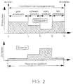
- FIG. 2 shows schematically the process control adapted by means of the method according to the invention in the regeneration of a foundry sand containing a large amount of bentonite.
- the entire regeneration period is divided into several time periods, the lengths of which are determined by the sensors 18a, 18b and 19a, 19b.
- the controller automatically switches the regenerator to higher speeds and lower through-air quantities 8 with adapted amplification of the cross air 11.
- the now weak grinding phase t1-t2 still adhering active bentonite is rubbed on the grains of sand and discharged alongside increasing amounts of hard bentonite, core binder residues and other fiber. It is recommended to switch the exhaust air damper 23 to release the exhaust air path 24 with separation of the residual materials.
- the actual strong grinding phase t2-t3 is switched, in which the large mass of hard bentonite shells and the corners and edges of the grains of sand are ground.
- the phase t3-t4 of fine dust removal which is particularly important for the regenerate quality, which ends at t4 with the discharge of the regenerate.
- the time t4 differs from sand to sand, its exact compliance is essential for high-quality cast production, but is guaranteed by the method according to the invention.
- the regenerator Under the control of the dust density in the exhaust air, the regenerator goes through several regeneration stages, the duration and grinding intensity of which depend on the amount and hardness of the foreign substances baked or adhered to the sand grains, the degree of filling and the performance of the regenerator.
- the process control can take place in stages or can also run smoothly in the case of fuzzy control. Although it is particularly effective with bentonite-containing old sands, it can also be used for the regeneration of synthetic resin-containing materials alone.
- the impact generator P shown schematically in FIG. 3 has two cells 31 and 32, each with a blow pipe 25, 26.
- the air supply to the blowpipes 25, 26 is regulated by an associated valve 27, 28.
- the interiors of the cells 31, 32 are connected to one another by a motor-adjustable transfer flap 30.
- Each cell 31, 32 and also the cascade classifier K, which is supplied with air via a control valve 29, has its own exhaust air line 12, in which a measuring point 18 is attached to determine the dust density in the exhaust air flowing through.
- a second measuring point 19 is provided above the measuring point 18, the sensors of which respond to the valuable substances in the exhaust air and the signals of which control the position of a deflection flap 23 between the exhaust air paths 20 and 24.
- the cascade classifier K is equipped with a separator 33 equipped for oversize grain that is transferred to a bunker, not shown.
- the medium regenerate free of loose dust and oversize is collected in a bunker B, from which, depending on the intended use, it is either taken off directly or fed to a regenerator S, which is designed as a sanding machine, for regeneration.
- the prepared waste sand is filled into the first cell 31 through the opening 16 and blown against the impact bell 34 with a low air intensity.
- the dust consisting mainly of coal dust and active bentonite in the exhaust air is conducted to a material separator by means of the flap 23 in the position shown. If, on the other hand, the sensors of the measuring point 19 determine no or only a small proportion of active bentonite in relation to the total amount of dust detected by the underlying sensor 18, the flap 23 is switched to the exhaust air path 24 to form a residue separator.
- the pneumatic impact regenerator can be operated in continuous or batch operation. If the measured dust density in the exhaust air of the first cell 31 falls below a preselected limit value, the transfer flap 30 is moved into such a position that the sand is increasingly transferred into the second cell 32. In it, it is blown against the impact bell 35 with a higher intensity.
- the air supply is limited to such a value that foreign substances adhering to the grains are loosened and detached, but the grain of sand is not broken up. In the interest of low sand wear, a larger proportion of foreign substances on the grains of the sand trickling down into the cascade classifier K is consciously accepted.
- the sand In the cascade classifier K, which can also act as a fluid bed regenerator, the sand is dusted off and separated from oversize particles.
- the sand which is now free of loose dust, can be used directly for hot box or cold resin cores or used to refresh the molding sand.
- This regenerator can also be used as a control device for determining the remaining hard bentonite and / or other foreign substance residues on the sand grains if the sand is subjected to a short heavy grinding phase of, for example, 5 seconds. This is of interest, for example, to check the suitability of regenerated materials for various purposes and the binder consumption.
- the impact regenerator can also be provided with a flat floor over which at least one grinding rotor works between the blowpipes.
- the pre-regeneration can also be carried out in other than pneumatic impact cleaners, or the dust density can also be measured in bypass lines.
Landscapes
- Engineering & Computer Science (AREA)
- Mechanical Engineering (AREA)
- Combined Means For Separation Of Solids (AREA)
- Mold Materials And Core Materials (AREA)
- Feedback Control In General (AREA)
Applications Claiming Priority (4)
| Application Number | Priority Date | Filing Date | Title |
|---|---|---|---|
| DE4224493 | 1992-07-24 | ||
| DE19924224493 DE4224493A1 (de) | 1992-07-24 | 1992-07-24 | Verfahren und Vorrichtung zum Regenerieren von Giessereisand |
| DE4315893A DE4315893A1 (de) | 1992-07-24 | 1993-05-12 | Verfahren und Vorrichtung zum Regenerieren von Gießereisand |
| DE4315893 | 1993-05-12 |
Publications (2)
| Publication Number | Publication Date |
|---|---|
| EP0580084A2 true EP0580084A2 (fr) | 1994-01-26 |
| EP0580084A3 EP0580084A3 (fr) | 1995-01-11 |
Family
ID=25916895
Family Applications (1)
| Application Number | Title | Priority Date | Filing Date |
|---|---|---|---|
| EP93111415A Withdrawn EP0580084A3 (fr) | 1992-07-24 | 1993-07-16 | Appareil et procédé pour la régénération de sable de fonderie. |
Country Status (5)
| Country | Link |
|---|---|
| US (1) | US5515907A (fr) |
| EP (1) | EP0580084A3 (fr) |
| JP (1) | JPH06154942A (fr) |
| DE (1) | DE4315893A1 (fr) |
| TR (1) | TR27795A (fr) |
Cited By (2)
| Publication number | Priority date | Publication date | Assignee | Title |
|---|---|---|---|---|
| EP0628367A3 (fr) * | 1993-06-01 | 1995-04-26 | Badische Maschf Gmbh | Procédé pour la régénération de sable de fonderie usé. |
| CN105094038A (zh) * | 2015-06-17 | 2015-11-25 | 浙江省建筑科学设计研究院有限公司 | 建筑工地环境监测改善装置及其控制方法 |
Families Citing this family (14)
| Publication number | Priority date | Publication date | Assignee | Title |
|---|---|---|---|---|
| KR100402412B1 (ko) * | 2001-10-25 | 2003-11-01 | 기원금속(주) | 주물사 재생장치 및 그 재생방법 |
| US20040051078A1 (en) * | 2002-09-12 | 2004-03-18 | Gernon Michael David | Reactive amine catalysts for use in PUCB foundry binder |
| WO2011074628A1 (fr) * | 2009-12-18 | 2011-06-23 | 株式会社松井工業 | Dispositif de polissage de corps granuleux, dispositif de reproduction de sable de fonderie et dispositif de génération de particules |
| EP2347833B1 (fr) | 2010-01-26 | 2015-05-27 | SKG Aufbereitungstechnik GmbH | Installation et procédé pour enlever des poussières avec épaisseur réglable de lit de matériau |
| KR101173053B1 (ko) * | 2010-06-30 | 2012-08-13 | 현대자동차주식회사 | 초음파를 이용한 폐주물사 점결제 박리장치 |
| EP2666562B1 (fr) * | 2012-05-25 | 2014-07-23 | Technofond Giessereihilfsmittel GmbH | Dispositif de régénération |
| DE102012105257B4 (de) | 2012-06-18 | 2018-06-07 | HARTING Electronics GmbH | Isolierkörper eines Steckverbinders |
| JP5827927B2 (ja) * | 2012-06-20 | 2015-12-02 | 新東工業株式会社 | 鋳物砂再生装置 |
| DE102012211650B3 (de) * | 2012-07-04 | 2013-10-10 | R. Scheuchl Gmbh | Verfahren zur Bestimmung der Qualität eines wiederaufbereiteten Gießereisands |
| CN102896275B (zh) * | 2012-07-23 | 2015-08-19 | 机械工业第四设计研究院 | 一种旧砂再生机构 |
| JP5718509B1 (ja) * | 2014-06-11 | 2015-05-13 | 株式会社清田鋳機 | 鋳物砂の再生装置 |
| JP6791100B2 (ja) * | 2017-11-15 | 2020-11-25 | 新東工業株式会社 | 鋳型ばらしシステム |
| CN110961572B (zh) * | 2019-12-31 | 2021-11-09 | 合肥正特机械有限公司 | 一种用于机械铸造的自动化洗砂装置 |
| US12390815B1 (en) * | 2024-10-24 | 2025-08-19 | KB Foundry Services, LLC | Method and system for cleaning sand |
Family Cites Families (13)
| Publication number | Priority date | Publication date | Assignee | Title |
|---|---|---|---|---|
| US3600574A (en) * | 1969-05-12 | 1971-08-17 | Gen Motors Corp | Radiometric method and apparatus for measuring and controlling foundry sand moisture |
| FR2272387B1 (fr) * | 1974-05-20 | 1976-10-15 | Rech Ind Liants Hy Centre Et | |
| JPS5335622A (en) * | 1976-09-16 | 1978-04-03 | Hitachi Ltd | Method and apparatus to regenerate used cast sand |
| US4177952A (en) * | 1978-04-24 | 1979-12-11 | National Engineering Company | Impact scrubber |
| US4436138A (en) * | 1980-07-23 | 1984-03-13 | Nippon Chuzo Kabushiki Kaisha | Method of and apparatus for reclaiming molding sand |
| SU1006036A1 (ru) * | 1981-10-02 | 1983-03-23 | Всесоюзный научно-исследовательский институт литейного машиностроения, литейной технологии и автоматизации литейного производства | Устройство дл сухой очистки зернистых материалов |
| JPS6092041A (ja) * | 1983-10-26 | 1985-05-23 | Hitachi Metals Ltd | 鋳物砂の微粉量測定方法 |
| US4709862A (en) * | 1987-01-30 | 1987-12-01 | Leidel Dieter S | Method of reclaiming green sand |
| ES2034025T3 (es) * | 1988-05-26 | 1993-04-01 | Pohl Giessereitechnik | Procedimiento para la recuperacion de arena usada de fundicion y su equipo correspondiente. |
| CH680498A5 (fr) * | 1989-11-28 | 1992-09-15 | Fischer Ag Georg | |
| CH680499A5 (fr) * | 1989-12-15 | 1992-09-15 | Fischer Ag Georg | |
| CH681434A5 (fr) * | 1990-01-31 | 1993-03-31 | Fischer Ag Georg | |
| US4978076A (en) * | 1990-03-28 | 1990-12-18 | Gmd Engineered Systems, Inc. | Method for separating hazardous substances in waste foundry sands |
-
1993
- 1993-05-12 DE DE4315893A patent/DE4315893A1/de not_active Withdrawn
- 1993-07-16 EP EP93111415A patent/EP0580084A3/fr not_active Withdrawn
- 1993-07-22 US US08/096,655 patent/US5515907A/en not_active Expired - Fee Related
- 1993-07-22 JP JP5181232A patent/JPH06154942A/ja active Pending
- 1993-07-22 TR TR00620/93A patent/TR27795A/xx unknown
Cited By (2)
| Publication number | Priority date | Publication date | Assignee | Title |
|---|---|---|---|---|
| EP0628367A3 (fr) * | 1993-06-01 | 1995-04-26 | Badische Maschf Gmbh | Procédé pour la régénération de sable de fonderie usé. |
| CN105094038A (zh) * | 2015-06-17 | 2015-11-25 | 浙江省建筑科学设计研究院有限公司 | 建筑工地环境监测改善装置及其控制方法 |
Also Published As
| Publication number | Publication date |
|---|---|
| US5515907A (en) | 1996-05-14 |
| TR27795A (tr) | 1995-08-29 |
| JPH06154942A (ja) | 1994-06-03 |
| EP0580084A3 (fr) | 1995-01-11 |
| DE4315893A1 (de) | 1994-11-17 |
Similar Documents
| Publication | Publication Date | Title |
|---|---|---|
| EP0580084A2 (fr) | Appareil et procédé pour la régénération de sable de fonderie | |
| EP0125384B1 (fr) | Procédé pour la régénération de sable de décochage de fonderie et dispositif pour la mise en oeuvre du procédé | |
| DE4109167A1 (de) | Verfahren zum aufbereiten von (giesserei-)altsand | |
| DE69111611T2 (de) | In einer zwischenphase arbeitender zyklontrenner. | |
| WO2016150835A1 (fr) | Dispositif de refroidissement de sable de moulage | |
| DE69003495T2 (de) | Verfahren zur Altsandaufbereitung. | |
| DE2100235C3 (de) | Anlage zum Trockenvermahlen von vorgebrochenen Rohmaterialien in einem gechlossenen Kreislaufsystem | |
| DE2738118A1 (de) | Filternder abscheider mit staubrueckfuehrung | |
| DE3900664C2 (fr) | ||
| DE4212097C2 (fr) | ||
| DE1533558B1 (de) | Vorrichtung zum pneumatischen Aufbereiten eines pulverfoermigen Stoffes in einer Wirbelschicht | |
| EP0276750B1 (fr) | Procédé et dispositif pour la préparation de matériaux en vrac, en particulier de grenailles abrasives | |
| CH634536A5 (de) | Verfahren zur muellverwertung und abwasseraufbereitung und mehrstufige filtrationsvorrichtung zur durchfuehrung dieses verfahrens. | |
| DE60010775T2 (de) | Verfahren und Vorrichtung zur Wiederaufbereitung von Giessereisand | |
| DE69421687T2 (de) | Verfahren und einrichtung zur zerkleinerung von verbrauchten feuerfesten auskleidungen und dergleichen | |
| AT402480B (de) | Verfahren zur regenerierbehandlung von überwiegend tongebundenem giesserei-altsand | |
| EP0149595A2 (fr) | Procédé et dispositif de régénération de sables de fonderie | |
| DE4224493A1 (de) | Verfahren und Vorrichtung zum Regenerieren von Giessereisand | |
| EP0576922A1 (fr) | Procédé et dispositif pour la régénération de sable de fonderie | |
| DE3616218C1 (en) | Method for continuous drying of water-containing bulk materials | |
| DE2952642A1 (de) | Verfahren und vorrichtung zur trockenen heissreinigung von schadstoffhaltigen gasen | |
| EP0767019B1 (fr) | Procédé et dispositif pour la régénération de sable de fonderie | |
| EP0628367B1 (fr) | Procédé pour la régénération de sable de fonderie usé | |
| DE3916676C2 (fr) | ||
| EP0300297B1 (fr) | Procédé et installation de traitement de produits granulaires utilisés dans le traitement hivernal de chaussées |
Legal Events
| Date | Code | Title | Description |
|---|---|---|---|
| PUAI | Public reference made under article 153(3) epc to a published international application that has entered the european phase |
Free format text: ORIGINAL CODE: 0009012 |
|
| AK | Designated contracting states |
Kind code of ref document: A2 Designated state(s): AT BE CH DE DK ES FR GB IT LI LU NL SE |
|
| PUAL | Search report despatched |
Free format text: ORIGINAL CODE: 0009013 |
|
| AK | Designated contracting states |
Kind code of ref document: A3 Designated state(s): AT BE CH DE DK ES FR GB IT LI LU NL SE |
|
| 17P | Request for examination filed |
Effective date: 19950419 |
|
| STAA | Information on the status of an ep patent application or granted ep patent |
Free format text: STATUS: THE APPLICATION IS DEEMED TO BE WITHDRAWN |
|
| 18D | Application deemed to be withdrawn |
Effective date: 19970201 |