EP0580110A1 - Rauchdetektionsvorrichtung für einen Feueralarm - Google Patents
Rauchdetektionsvorrichtung für einen Feueralarm Download PDFInfo
- Publication number
- EP0580110A1 EP0580110A1 EP93111565A EP93111565A EP0580110A1 EP 0580110 A1 EP0580110 A1 EP 0580110A1 EP 93111565 A EP93111565 A EP 93111565A EP 93111565 A EP93111565 A EP 93111565A EP 0580110 A1 EP0580110 A1 EP 0580110A1
- Authority
- EP
- European Patent Office
- Prior art keywords
- data
- output
- output data
- smoke
- converting circuit
- Prior art date
- Legal status (The legal status is an assumption and is not a legal conclusion. Google has not performed a legal analysis and makes no representation as to the accuracy of the status listed.)
- Granted
Links
Images




Classifications
-
- G—PHYSICS
- G08—SIGNALLING
- G08B—SIGNALLING SYSTEMS, e.g. PERSONAL CALLING SYSTEMS; ORDER TELEGRAPHS; ALARM SYSTEMS
- G08B29/00—Checking or monitoring of signalling or alarm systems; Prevention or correction of operating errors, e.g. preventing unauthorised operation
- G08B29/18—Prevention or correction of operating errors
- G08B29/185—Signal analysis techniques for reducing or preventing false alarms or for enhancing the reliability of the system
-
- G—PHYSICS
- G08—SIGNALLING
- G08B—SIGNALLING SYSTEMS, e.g. PERSONAL CALLING SYSTEMS; ORDER TELEGRAPHS; ALARM SYSTEMS
- G08B17/00—Fire alarms; Alarms responsive to explosion
- G08B17/10—Actuation by presence of smoke or gases, e.g. automatic alarm devices for analysing flowing fluid materials by the use of optical means
- G08B17/103—Actuation by presence of smoke or gases, e.g. automatic alarm devices for analysing flowing fluid materials by the use of optical means using a light emitting and receiving device
- G08B17/107—Actuation by presence of smoke or gases, e.g. automatic alarm devices for analysing flowing fluid materials by the use of optical means using a light emitting and receiving device for detecting light-scattering due to smoke
Definitions
- the present invention relates to a high-sensitivity smoke detecting apparatus for fire alarm in which a plurality of sample gases are introduced into a smoke chamber in order to calibrate the sensitivity characteristic.
- a smoke detector When the sensitivity characteristic of a smoke detector is calibrated by introducing a plurality of sample gases into a smoke chamber, two kinds of pure gases such as oxygen gas and fleon 12 (F12: CCl2F2) gas, which have greatly different molecular weights, are generally alternately passed through the smoke chamber.
- the light emitted from a light emitting lamp is scattered by the molecules of the sample gases.
- the sensitivity characteristic of the smoke sensor is calibrated by utilizing the phenomenon that the scattered light is captured by a light receiving element.
- the densities of the pure gases are stable, when a pure gas is introduced into the smoke chamber and is detected as smoke, a very low value of smoke density is output.
- the density of the pure gas corresponds to the output low value of smoke density. This can thus be employed for calibrating the sensitivity characteristic of a high-sensitivity smoke detector.
- Fig. 7 shows the circuit of a principal portion of a conventional smoke detector.
- the light emitted from a xenon lamp (not shown) is scattered by smoke, and the scattered light is received by a light receiving element 81.
- the output signal from the light receiving element 81 is amplified by an amplifier 82, and the peak value thereof is held by a peak holding circuit 84.
- the data obtained by subtracting a predetermined value from the peak value using a subtraction circuit 85 is transmitted to a receiver through a signal output circuit 87.
- a gain adjusting variable resistor 83 adjusts the gain of the amplifier 82, and an offset adjusting variable resistor 86 adjusts the predetermined value subtracted from the peak value.
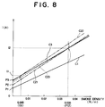
- Fig. 8 shows the values of current I output from the signal output circuit 87 relative to the smoke density (gas density) when pure oxygen gas and fleon 12 gas are alternately introduced into the smoke chamber.
- line C1 shows the characteristics when the sensitivity of the smoke detector is not adjusted
- line C3 shows the characteristics when the sensitivity has been adjusted.
- I1 and I2 the output currents of the signal output circuit 87 when oxygen gas is used and when fleon 12 gas is used are denoted by I1 and I2, respectively.
- Such adjustment of the sensitivity of the smoke detector is performed by regulating the slope of the line C1 and moving the line C1 in parallel.
- the output of the smoke detector is, in fact, adjusted while an ammeter or the like is observed.
- the fleon 12 gas is first introduced into the smoke chamber, and the slope of the characteristic line C1 is adjusted by operating the gain adjusting variable resistor 83 so that the output I of the signal output circuit 87 may become I2 to obtain the characteristics shown by a line C21.
- the oxygen gas is then introduced, and the line C21 is moved parallel so that the output I of the signal output circuit 87 may become I1 by operating the offset adjusting variable resistor 86 to obtain a line C22.
- the fleon 12 gas is again introduced, and the slope of the line C22 is adjusted by operating the gain adjusting variable resistor 83 so that the output I may become I2 to obtain a line C23.
- the above operation is repeated until the characteristic line C3 is obtained.
- An object of the present invention is to provide a smoke detecting apparatus for fire alarm in which the work of adjusting the sensitivity of a smoke detector can be easily made and completed within a short time.
- a smoke detecting apparatus for fire alarm of the present invention comprises a smoke chamber into which smoke to be detected is introduced, a light emitting lamp disposed in the smoke chamber, a light receiving element disposed in the smoke chamber so as to receive the light emitted from the light emitting lamp, an A/D converting circuit for converting the output signal from the light emitting element into a digital signal, a memory for storing data therein, computing means for storing as first calibration data the output data from the A/D converting circuit in the memory when the smoke chamber is filled with a first reference gas, storing as second calibration data the output data from the A/D converting circuit in the memory when the smoke chamber is filled with a second reference gas, and calculating a proper smoke density corresponding to the output data from the A/D converting circuit on the basis of the first and second calibration data and the output data from the A/D converting circuit, and display means for displaying the smoke density calculated by the computing means.
- Fig. 1 is a block diagram showing a smoke detecting apparatus according to a first embodiment of the present invention.
- a xenon lamp 10 and a light receiving element 20 are provided in a smoke chamber 30 in the state where the xenon lamp 10 and the light receiving element 20 are separated by a light shielding plate 34.
- the light emitted from the xenon lamp 10 is scattered by smoke in the smoke chamber 30 and then reaches the light receiving element 20.
- a high voltage required for emission is supplied to the xenon lamp 10 from a high-voltage generating circuit 12, and the emission timing thereof is controlled by the trigger signal supplied from a trigger circuit 11.
- the trigger circuit 11 generates the trigger signal on the basis of the control signal supplied from a control circuit 50.
- the smoke chamber 30 is connected to a sampling pipe 31 for introducing into the smoke chamber 30 an atmosphere where the smoke detector 1 is installed, and a pipe 32 for discharging the air in the smoke chamber 30 to the outside of the smoke detector 1.
- An aspiration fan 33 is provided in the pipe 32.
- An amplifier 40 amplifies the output signal from the light receiving element 20, the gain of the amplifier 40 being controlled by a gain switching circuit 41.
- a peak holding circuit 42 holds the peak of the output signal from the amplifier 40, and an A/D converting circuit 43 converts the analog signal output from the peak holding circuit 42 into a digital signal.
- the control circuit 50 comprises a microcomputer or the like for controlling the overall operation of the smoke detector 1 and determining the current smoke density in the smoke chamber 30 on the basis of the digital signal from the A/D converting circuit 43.
- a ROM (read only memory) 60 stores the program shown in the flow chart of Fig. 2.
- An EEPROM (electrically erasable and programmable ROM) 61 stores as first calibration data the output data from the A/D converting circuit 43 when pure oxygen gas (first reference gas) is sucked into the smoke chamber 30, for example, at 1 atm and room temperature, and stores as second calibration data the output data from the A/D converting circuit 43 when pure fleon 12 gas (second reference gas) is sucked into the smoke chamber 30.
- a RAM (randam access memory) 64 is a memory for working.
- a D/A converting circuit 71 converts the digital signal output from the control circuit 50 into an analog signal for transmitting the signal to a fire receiver 2 through a signal output circuit 72 and a connector C.
- the receiver 2 is provided with a smoke density display device 2d for displaying a smoke density, as shown in Figs. 4A to 4C.
- a calibration confirmation lamp circuit 74 indicates that the sensitivity of the smoke detector 1 is being adjusted.
- Switches SW1 and SW2 are lock-type switches which are operated according to the types of the gases used for calibrating the sensitivity of the smoke detector 1, and a switch SW3 is a nonlock-type switch which is turned on for 5 seconds or more when the sensitivity of the smoke detector 1 is calibrated.
- the EEPROM 61 for storing a detected value of a memory calibration reference gas is an example of memory for storing the output data from the A/D converting circuit 43 as first calibration data when the smoke chamber 30 is filled with a first reference gas, and for storing the output data from the A/D converting circuit 43 as second calibration data when the smoke chamber 30 is filled with a second reference gas.
- the EEPROM 61 is an electrically rewritable non-volatile memory.
- the control circuit 50 and the ROM 60 are examples of computing means for performing a predetermined calculation on the basis of the output data from the A/D converting circuit 43.
- the computing means computes output data required for displaying a proper smoke density corresponding to the output data from the A/D converting circuit 43 on the smoke density display device 2d of the fire receiver 2 on the basis of the first and second calibration data and the output data from the A/D converting circuit 43.
- the present output data from the A/D converting circuit 43 is x
- the output data required for displaying a smoke density corresponding to a first gas on the smoke density display device 2d is y1
- the output data required for displaying a smoke density corresponding to a second gas on the smoke density display device 2d is y2
- the output data required for displaying a proper density corresponding to the output data from the A/D converting circuit 43 on the smoke density display device 2d is y, as shown in Fig.
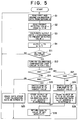
- Fig. 2 is a flowchart showing the operation of the first embodiment.
- Steps S11 to S23 indicate the preparatory operation for adjusting the sensitivity of the smoke detector 1
- Steps S1 to S4 indicate the smoke detecting operation including sensitivity adjustment.
- the switch SW1 is turned on, and the switch SW2 is turned off, while the smoke chamber 30 is filled with pure oxygen through the sample pipe 31 at 1 atm and room temperature.
- Step S11 the sensitivity adjustment command switch SW3 is turned on for 5 seconds or more.
- Step S12 the confirmation lamp of the calibration confirmation lamp circuit 74 is turned on, in Step S12, for 1 second for indicating that the operation of adjusting the sensitivity is started.
- Step S15 in the state where the smoke chamber 30 is filled with pure oxygen, the output signal from the light receiving element 20 is amplified, and the peak value of the amplified signal is held by the peak holding circuit 42, and is converted into digital data by the A/D converting circuit 43.
- the converted output data is stored as first calibration data x1 in the EEPROM 61.
- the smoke detecting operation (Steps S1 to S4) is then executed.
- the pure oxygen gas is then discharged from the pipe 32 by the aspiration fan 33, and the smoke chamber 30 is filled with pure fleon 12 through the sampling pipe 31 at 1 atm and room temperature.
- the switch SW1 is turned off, the switch SW2 is turned on, and the sensitivity adjustment command switch SW3 is turned on for 5 seconds or more.
- the confirmation lamp of the calibration confirmation lamp circuit 74 is turned on, in Step S12, for 1 second for indicating that the sensitivity adjusting operation is started. Since the switch SW1 is turned off and the switch SW2 is turned on, the flow moves to Step S22 through Steps S13 and S21.
- Step S22 in the state where the smoke chamber 30 is filled with the pure fleon 12, the output signal from the light receiving element 20 is amplified by the amplifier circuit 40, and the peak value of the amplified signal is held by the peak holding circuit 42, and is converted into digital data by the A/D converting circuit 43.
- the converted output data is stored as the second calibration data x2 in the EEPROM 61.
- the smoke detecting operation below (Steps S1 to S4) is then executed. If both switches SW1 and SW2 are turned on, the flow moves to Step S23 through Steps S13 and S14, and data other than the calibration data stored in the EEPROM 61 is erased in Step S23.
- the smoke density detecting operation including the sensitivity adjustment, i.e., the smoke detecting operation, is described below.
- Step S1 the first and second calibration data x1 and x2 are read from the EEPROM 61 in Step S1, and the present detected data (present output data from the A/D converting circuit 43) x is read in Step S2.
- Step S3 data y to be output to the D/A converting circuit 71 and required for displaying, on the smoke density display device 2d, a proper smoke density corresponding to the present output data x is calculated by the control device 50 using the ROM 60 on the basis of the first and second calibration data x1 and x2, the present detected data x, the output data y1 corresponding to the data x1 and the output data y2 corresponding to the data x2. Namely, the sensitivity is adjusted.
- the output data y1 is the data to be output to the D/A converting circuit 71 and required for displaying, on the smoke density display device 2d of the fire receiver 2, the smoke density (about 0.005 %/m) corresponding to oxygen gas used as the first reference gas.
- the output data y2 is the data to be output to the D/A converting circuit 71 and required for displaying, on the smoke density display device 2d of the fire receiver 2, the smoke density (about 0.035 %/m) corresponding to fleon 12 gas used as the second reference gas. Both output data y1 and y2 are previously calculated and stored in the ROM 60.
- the D/A converting circuit 71 converts the output data y into an analog signal which is sent to the fire receiver 2 by the signal output circuit 72.
- a proper smoke density corresponding to the present output data x from the A/D converting circuit 43 is displayed on the smoke density display device 2d. For example, if the present smoke density is 0.06 %/m, portions "OK” and “0.01" to "0.06" are lighted, as shown in Fig. 4C.
- the control circuit 50 since the control circuit 50 computes the output data required for displaying a proper smoke density on the basis of the first and second calibration data and the output data from the A/D converting circuit 43, the sensitivity can be adjusted by using the fist and second reference gases only once.
- the output data from the A/D converting circuit 43 can be used when the first reference gas is sucked in the smoke chamber 30 and when the output signal from the light receiving element 20 is amplified by the amplifier 40 with a gain Gh higher than the gain Gn at a set sensitivity.
- the output data from the A/D converting circuit 43 can be used when the second reference gas is sucked in the smoke chamber 30 and when the output signal from the light receiving element 20 is amplified by the amplifier 40 with the gain Gh higher than the gain Gn at a set sensitivity.
- the switch SW1 Before the adjustment of the sensitivity of the smoke detector 1 is executed, the switch SW1 is turned on and the switch SW2 is turned off while the smoke chamber 30 is filled with pure oxygen through the sample pipe 31, for example, at 1 atm and room temperature. In this state, the sensitivity adjustment command switch SW3 is turned on for 5 seconds or more.
- the confirmation lamp of the calibration confirmation lamp circuit 74 is turned on, in Step S12, for 1 second for indicating that the sensitivity adjusting operation is started. Since the switch SW1 is turned on and the switch SW2 is turned off, the flow moves to Step S16 through Steps S13 and S14.
- Step S16 the gain of the amplifier 40 is switched to the highest value by driving the gain switching circuit 41.
- Step S17 in the state where the smoke chamber 30 is filled with pure oxygen, the output signal from the light receiving element 20 is amplified, and the peak value of the amplified signal is held by the peak holding circuit 42, and is converted into digital data by the A/D converting circuit 43. The converted output data is stored as first calibration data x1h in the EEPROM 61.
- the gain of the amplifier 40 is then returned to the gain Gn at the set sensitivity in Step S18.
- the smoke detecting operation is then executed in Steps S1 to S4.
- Step S11 the sensitivity adjustment command switch SW3 is turned on for 5 seconds or more.
- Step S12 the confirmation lamp of the calibration confirmation lamp circuit 74 is turned on, in Step S12, for 1 second for indicating that the sensitivity adjusting operation is started in Step S12. Since the switch SW1 is turned off and the switch SW2 is turned on, the flow moves to Step S24 through the Steps S13 and S21.
- Step S24 the gain of the amplifier 40 is switched to the highest value by driving the gain switching circuit 41.
- Step S25 in the state where the smoke chamber 30 is filled with the pure fleon 12 gas, the output signal from the light receiving element 20 is amplified by the amplifier 40, and the peak value of the amplified signal is held by the peak holding circuit 42, and is converted into digital data by the A/D converting circuit 43.
- the converted output data is stored as second calibration data x2h in the EEPROM 61.
- Step S18 the gain of the amplifier 40 is returned to the gain Gn at the set sensitivity.
- the smoke detecting operation is then executed in Steps S1 to S4. If both switches SW1 and SW2 are turned on, data other than the calibration data in the data stored in the EEPROM 61 is erased in Step S23.
- the smoke density detecting operation including sensitivity adjustment, i.e., the smoke detecting operation, is described below.
- the first and second calibration data x1h and x2h are read from the EEPROM 61 in Step S1, and the present detected data (the present output data from the A/D converting circuit 43) x is read in Step S2.
- the data y to be output to the D/A converting circuit 71 required for displaying a proper smoke density corresponding to the present output data x on the smoke density display device 2d is computed by the control circuit 50 using the ROM 60 in Step S3. Namely, the sensitivity is adjusted.
- x1 is the output value of the A/D converting circuit 43 when the smoke chamber 30 is filled with the first reference gas (oxygen) with the set gain Gn
- x2 is the output value of the A/D converting circuit 43 when the smoke chamber 30 is filled with the second reference gas (fleon 12) with the set gain Gn.
- the thus-determined output data y is supplied to the D/A converting circuit 71 in Step S4.
- the output data y is converted into an analog value by the D/A converting circuit 71, and is sent to the fire receiver 2 by the signal output circuit 72.
- a proper smoke density value corresponding to the present output data x from the A/D converting circuit 43 is displayed on the smoke density display device 2d.
- the sensitivity can be adjusted with high precision in a region of smoke density values higher than the density of the gases used for obtaining the calibration data, for example, a smoke density of about 0.05 or 0.10 %/m.
- the gain of the amplifier 40 is switched to the highest value by driving the gain switching circuit 41 when the sensitivity characteristic is calibrated, data may be amplified with a gain Gh higher than the gain Gn at the set sensitivity in place of amplification with the highest gain.
- the data y to be output to the D/A converting circuit 71 corresponding to the present output data x is computed by using the data x1h, x2h, y1 , y2 and Gn/Gh
- the output data y can be computed by using the data x1h, x2h, y1h and y2h without using the data Gn/Gh.
- the data y1h and y2h are previously calculated by the equations below using the output data x1 from the A/D converting circuit 43 for the first reference gas when the amplifier 40 has the set sensitivity, the output data x2 from the A/D converting circuit 43 for the second reference gas when the amplifier 40 has the set sensitivity, the output data y1 from the signal output circuit 72 required for displaying a smoke density corresponding to the first reference gas on the smoke density display device 2d, and the output data y2 from the signal output circuit 72 required for displaying a smoke density corresponding to the second reference gas on the smoke density display device 2d.
- y1h ⁇ (y2 - y1)/(x2 - x1) ⁇ ⁇ (Gh/Gn) ⁇ x1 + (y1 ⁇ x2 - y2 ⁇ x1)/(x2 - x1)
- y2h ⁇ (y2 - y1)/(x2 - x1) ⁇ ⁇ (Gh/Gn) ⁇ x2 + (y1 ⁇ x2 - y2 ⁇ x1)/(x2 - x1)
- oxygen gas and fleon 12 gas are used as the reference gases, other pure gases may be used, and more than two kinds of pure gases may be used.
- the xenon lamp is used, a light emitting lamp other than xenon lamp may be used.
- the analog signal is sent to the fire receiver 2
- a digital signal such as a pulse code or the like may be sent to the fire receiver 2.
- memory such as the EEPROM 61 for storing the first and second calibration data and the computing means are provided on the side of the smoke detector 1, one or both of the devices may be provided on the side of the fire receiver 2 or a transmitter (not shown).
- the smoke density display device 2d is provided on the side of the fire receiver 2
- the display device may be provided on the smoke detector 1.
Landscapes
- Physics & Mathematics (AREA)
- General Physics & Mathematics (AREA)
- Engineering & Computer Science (AREA)
- Computer Security & Cryptography (AREA)
- Chemical & Material Sciences (AREA)
- Analytical Chemistry (AREA)
- Business, Economics & Management (AREA)
- Emergency Management (AREA)
- Fire-Detection Mechanisms (AREA)
- Investigating Or Analysing Materials By Optical Means (AREA)
Applications Claiming Priority (4)
| Application Number | Priority Date | Filing Date | Title |
|---|---|---|---|
| JP214669/92 | 1992-07-20 | ||
| JP04214669A JP3121134B2 (ja) | 1992-07-20 | 1992-07-20 | 煙感知装置 |
| JP32268692A JP3181734B2 (ja) | 1992-11-06 | 1992-11-06 | 火災感知装置 |
| JP322686/92 | 1992-11-06 |
Publications (2)
| Publication Number | Publication Date |
|---|---|
| EP0580110A1 true EP0580110A1 (de) | 1994-01-26 |
| EP0580110B1 EP0580110B1 (de) | 1997-10-22 |
Family
ID=26520443
Family Applications (1)
| Application Number | Title | Priority Date | Filing Date |
|---|---|---|---|
| EP93111565A Expired - Lifetime EP0580110B1 (de) | 1992-07-20 | 1993-07-19 | Rauchdetektionsvorrichtung für einen Feueralarm |
Country Status (5)
| Country | Link |
|---|---|
| US (1) | US5473314A (de) |
| EP (1) | EP0580110B1 (de) |
| AU (1) | AU645931B1 (de) |
| DE (1) | DE69314712T2 (de) |
| HK (1) | HK1003853A1 (de) |
Cited By (7)
| Publication number | Priority date | Publication date | Assignee | Title |
|---|---|---|---|---|
| RU2168214C2 (ru) * | 1999-08-20 | 2001-05-27 | Закрытое акционерное общество Производственное объединение "Спецавтоматика" | Камера для испытаний пожарных извещателей |
| WO2006024960A1 (en) * | 2004-07-09 | 2006-03-09 | Tyco Safety Products Canada Ltd. | Smoke detector calibration |
| CN101751745B (zh) * | 2008-12-16 | 2013-02-20 | 深圳富泰宏精密工业有限公司 | 具有烟雾侦测功能的便携式电子装置及烟雾侦测方法 |
| CN104297426A (zh) * | 2014-09-28 | 2015-01-21 | 佛山高富中石油燃料沥青有限责任公司 | 一种沥青烟气测定方法 |
| US9396637B2 (en) | 2012-07-13 | 2016-07-19 | Walter Kidde Portable Equipment, Inc | Photoelectric smoke detector with drift compensation |
| WO2017101039A1 (en) * | 2015-12-16 | 2017-06-22 | Honeywell International Inc. | Systems, methods, and devices for calibrating particulate matter sensors |
| CN114999133A (zh) * | 2022-06-06 | 2022-09-02 | 浙江聚森检测科技有限公司 | 一种自动调节气体报警器定位位置的校准设备 |
Families Citing this family (13)
| Publication number | Priority date | Publication date | Assignee | Title |
|---|---|---|---|---|
| US6501810B1 (en) | 1998-10-13 | 2002-12-31 | Agere Systems Inc. | Fast frame synchronization |
| US5546074A (en) * | 1993-08-19 | 1996-08-13 | Sentrol, Inc. | Smoke detector system with self-diagnostic capabilities and replaceable smoke intake canopy |
| JP3251407B2 (ja) * | 1993-12-22 | 2002-01-28 | 能美防災株式会社 | 光電式火災感知器および調整装置 |
| TW369197U (en) * | 1998-01-02 | 1999-09-01 | Everday Technology Co Ltd | Detecting alarm |
| US6876305B2 (en) * | 1999-12-08 | 2005-04-05 | Gentex Corporation | Compact particle sensor |
| US6225910B1 (en) | 1999-12-08 | 2001-05-01 | Gentex Corporation | Smoke detector |
| JP4396079B2 (ja) † | 2000-03-28 | 2010-01-13 | パナソニック電工株式会社 | 粒子センサー |
| US7616126B2 (en) * | 2006-07-18 | 2009-11-10 | Gentex Corporation | Optical particle detectors |
| CN111263958B (zh) * | 2017-10-30 | 2022-05-27 | 开利公司 | 检测器装置中的补偿器 |
| US11879840B2 (en) | 2018-12-11 | 2024-01-23 | Carrier Corporation | Calibration of an optical detector using a micro-flow chamber |
| WO2020123155A1 (en) | 2018-12-11 | 2020-06-18 | Carrier Corporation | Calibration of an optical detector |
| EP3894838B1 (de) | 2018-12-11 | 2026-03-18 | Carrier Corporation | Kalibrierung eines optischen detektors |
| US11676466B2 (en) | 2020-08-19 | 2023-06-13 | Honeywell International Inc. | Self-calibrating fire sensing device |
Citations (4)
| Publication number | Priority date | Publication date | Assignee | Title |
|---|---|---|---|---|
| US4317113A (en) * | 1979-08-24 | 1982-02-23 | Hochiki Corporation | Photoelectric smoke sensor |
| EP0054680A1 (de) * | 1980-12-18 | 1982-06-30 | Cerberus Ag | Rauchmelder nach dem Strahlungs-Extinktions-Prinzip |
| GB2175392A (en) * | 1985-04-26 | 1986-11-26 | Hochiki Co | Output correction system for analogue sensor |
| GB2188725A (en) * | 1986-03-18 | 1987-10-07 | Hochiki Co | Detecting system and detector |
Family Cites Families (9)
| Publication number | Priority date | Publication date | Assignee | Title |
|---|---|---|---|---|
| US3866195A (en) * | 1973-05-07 | 1975-02-11 | Fire Alert Company | Combustion product detector and method of calibrating |
| US4097850A (en) * | 1976-11-01 | 1978-06-27 | Pittway Corporation | Means for adjusting and for testing a detecting device |
| US4193069A (en) * | 1978-03-13 | 1980-03-11 | American District Telegraph Company | Latching alarm smoke detector |
| US4524351A (en) * | 1981-08-20 | 1985-06-18 | Nittan Company, Limited | Smoke detector |
| US4595914A (en) * | 1983-04-11 | 1986-06-17 | Pittway Corporation | Self-testing combustion products detector |
| US5079422A (en) * | 1989-09-06 | 1992-01-07 | Gaztech Corporation | Fire detection system using spatially cooperative multi-sensor input technique |
| EP0423489A1 (de) * | 1989-09-15 | 1991-04-24 | Cerberus Ag | Brandmeldeanlage mit Ueberwachung |
| US5255074A (en) * | 1991-04-17 | 1993-10-19 | Baker Hughes, Inc. | Concentration measuring apparatus and calibration method |
| US5281810A (en) * | 1992-12-30 | 1994-01-25 | Allen-Bradley Company, Inc. | Photoelectric control unit adapted for determining its own operating margin having dual variable-gain amplifier |
-
1993
- 1993-07-15 US US08/091,271 patent/US5473314A/en not_active Expired - Fee Related
- 1993-07-19 EP EP93111565A patent/EP0580110B1/de not_active Expired - Lifetime
- 1993-07-19 AU AU42063/93A patent/AU645931B1/en not_active Ceased
- 1993-07-19 DE DE69314712T patent/DE69314712T2/de not_active Expired - Fee Related
-
1998
- 1998-04-08 HK HK98102959A patent/HK1003853A1/en not_active IP Right Cessation
Patent Citations (4)
| Publication number | Priority date | Publication date | Assignee | Title |
|---|---|---|---|---|
| US4317113A (en) * | 1979-08-24 | 1982-02-23 | Hochiki Corporation | Photoelectric smoke sensor |
| EP0054680A1 (de) * | 1980-12-18 | 1982-06-30 | Cerberus Ag | Rauchmelder nach dem Strahlungs-Extinktions-Prinzip |
| GB2175392A (en) * | 1985-04-26 | 1986-11-26 | Hochiki Co | Output correction system for analogue sensor |
| GB2188725A (en) * | 1986-03-18 | 1987-10-07 | Hochiki Co | Detecting system and detector |
Cited By (12)
| Publication number | Priority date | Publication date | Assignee | Title |
|---|---|---|---|---|
| RU2168214C2 (ru) * | 1999-08-20 | 2001-05-27 | Закрытое акционерное общество Производственное объединение "Спецавтоматика" | Камера для испытаний пожарных извещателей |
| WO2006024960A1 (en) * | 2004-07-09 | 2006-03-09 | Tyco Safety Products Canada Ltd. | Smoke detector calibration |
| US7224284B2 (en) | 2004-07-09 | 2007-05-29 | Tyco Safety Products Canada Ltd. | Smoke detector calibration |
| US7474226B2 (en) | 2004-07-09 | 2009-01-06 | Tyco Safety Products Canada Ltd. | Smoke detector calibration |
| EP1769473A4 (de) * | 2004-07-09 | 2010-05-05 | Tyco Safety Products Canada Ltd | Kalibrierung eines rauchmelders |
| CN101751745B (zh) * | 2008-12-16 | 2013-02-20 | 深圳富泰宏精密工业有限公司 | 具有烟雾侦测功能的便携式电子装置及烟雾侦测方法 |
| US9396637B2 (en) | 2012-07-13 | 2016-07-19 | Walter Kidde Portable Equipment, Inc | Photoelectric smoke detector with drift compensation |
| CN104297426A (zh) * | 2014-09-28 | 2015-01-21 | 佛山高富中石油燃料沥青有限责任公司 | 一种沥青烟气测定方法 |
| CN104297426B (zh) * | 2014-09-28 | 2016-07-06 | 佛山高富中石油燃料沥青有限责任公司 | 一种沥青烟气测定方法 |
| WO2017101039A1 (en) * | 2015-12-16 | 2017-06-22 | Honeywell International Inc. | Systems, methods, and devices for calibrating particulate matter sensors |
| CN114999133A (zh) * | 2022-06-06 | 2022-09-02 | 浙江聚森检测科技有限公司 | 一种自动调节气体报警器定位位置的校准设备 |
| CN114999133B (zh) * | 2022-06-06 | 2022-12-23 | 浙江聚森检测科技有限公司 | 一种自动调节气体报警器定位位置的校准设备 |
Also Published As
| Publication number | Publication date |
|---|---|
| HK1003853A1 (en) | 1998-11-06 |
| DE69314712D1 (de) | 1997-11-27 |
| DE69314712T2 (de) | 1998-05-20 |
| US5473314A (en) | 1995-12-05 |
| AU645931B1 (en) | 1994-01-27 |
| EP0580110B1 (de) | 1997-10-22 |
Similar Documents
| Publication | Publication Date | Title |
|---|---|---|
| EP0580110B1 (de) | Rauchdetektionsvorrichtung für einen Feueralarm | |
| HK1003853B (en) | Smoke detecting apparatus for fire alarm | |
| EP0596500B1 (de) | Rauchdetektierungsvorrichtung für Feueralarm | |
| US4589072A (en) | Apparatus for automatically measuring and controlling chemical reaction amount | |
| US4151738A (en) | Toxic gas monitor having automatic calibration | |
| US4930095A (en) | Output correction system for analog sensor | |
| US5995859A (en) | Method and apparatus for accurately measuring the saturated oxygen in arterial blood by substantially eliminating noise from the measurement signal | |
| EP0242946B1 (de) | Eichung von kombinierten Sauerstoff- und Brennstoffanalysegeräten | |
| US4162531A (en) | Method and apparatus for programmable and remote numeric control and calibration of electronic instrumentation | |
| CA2129113C (en) | Multiple k factor, selectable gas detector | |
| JP4154274B2 (ja) | ガス濃度検出方法およびガス濃度検出装置 | |
| US5627307A (en) | Method for measuring intensity index of odor | |
| US5381131A (en) | Smoke detecting apparatus for fire alarm | |
| JP3121134B2 (ja) | 煙感知装置 | |
| US4043676A (en) | Photometer | |
| JP3181734B2 (ja) | 火災感知装置 | |
| US4498140A (en) | Automated self calibrating exposure computer | |
| US7123019B2 (en) | Polarographic densitometer | |
| JPH09178511A (ja) | 感度調整装置並びに感度調整方法および感度調整システムおよび物理量検出システム | |
| JPS59198348A (ja) | 食肉分析装置の自動較正装置 | |
| US4091277A (en) | Photon detection and counting system | |
| JPH02306112A (ja) | センサの感度調整装置 | |
| JPH09502522A (ja) | X線放射を測定する方法および計器 | |
| JPH08128956A (ja) | ガス濃度測定装置 | |
| JPH02120635A (ja) | リークデテクタ |
Legal Events
| Date | Code | Title | Description |
|---|---|---|---|
| PUAI | Public reference made under article 153(3) epc to a published international application that has entered the european phase |
Free format text: ORIGINAL CODE: 0009012 |
|
| AK | Designated contracting states |
Kind code of ref document: A1 Designated state(s): CH DE FR GB LI |
|
| 17P | Request for examination filed |
Effective date: 19940629 |
|
| GRAG | Despatch of communication of intention to grant |
Free format text: ORIGINAL CODE: EPIDOS AGRA |
|
| 17Q | First examination report despatched |
Effective date: 19970303 |
|
| GRAH | Despatch of communication of intention to grant a patent |
Free format text: ORIGINAL CODE: EPIDOS IGRA |
|
| GRAH | Despatch of communication of intention to grant a patent |
Free format text: ORIGINAL CODE: EPIDOS IGRA |
|
| GRAA | (expected) grant |
Free format text: ORIGINAL CODE: 0009210 |
|
| AK | Designated contracting states |
Kind code of ref document: B1 Designated state(s): CH DE FR GB LI |
|
| REG | Reference to a national code |
Ref country code: CH Ref legal event code: NV Representative=s name: WILLIAM BLANC & CIE CONSEILS EN PROPRIETE INDUSTRI Ref country code: CH Ref legal event code: EP |
|
| REF | Corresponds to: |
Ref document number: 69314712 Country of ref document: DE Date of ref document: 19971127 |
|
| ET | Fr: translation filed | ||
| PLBE | No opposition filed within time limit |
Free format text: ORIGINAL CODE: 0009261 |
|
| STAA | Information on the status of an ep patent application or granted ep patent |
Free format text: STATUS: NO OPPOSITION FILED WITHIN TIME LIMIT |
|
| 26N | No opposition filed | ||
| PGFP | Annual fee paid to national office [announced via postgrant information from national office to epo] |
Ref country code: FR Payment date: 19990719 Year of fee payment: 7 |
|
| PGFP | Annual fee paid to national office [announced via postgrant information from national office to epo] |
Ref country code: CH Payment date: 19990722 Year of fee payment: 7 |
|
| PG25 | Lapsed in a contracting state [announced via postgrant information from national office to epo] |
Ref country code: LI Free format text: LAPSE BECAUSE OF NON-PAYMENT OF DUE FEES Effective date: 20000731 Ref country code: CH Free format text: LAPSE BECAUSE OF NON-PAYMENT OF DUE FEES Effective date: 20000731 |
|
| REG | Reference to a national code |
Ref country code: CH Ref legal event code: PL |
|
| PG25 | Lapsed in a contracting state [announced via postgrant information from national office to epo] |
Ref country code: FR Free format text: LAPSE BECAUSE OF NON-PAYMENT OF DUE FEES Effective date: 20010330 |
|
| REG | Reference to a national code |
Ref country code: FR Ref legal event code: ST |
|
| PGFP | Annual fee paid to national office [announced via postgrant information from national office to epo] |
Ref country code: GB Payment date: 20010704 Year of fee payment: 9 |
|
| PGFP | Annual fee paid to national office [announced via postgrant information from national office to epo] |
Ref country code: DE Payment date: 20010925 Year of fee payment: 9 |
|
| REG | Reference to a national code |
Ref country code: GB Ref legal event code: IF02 |
|
| PG25 | Lapsed in a contracting state [announced via postgrant information from national office to epo] |
Ref country code: GB Free format text: LAPSE BECAUSE OF NON-PAYMENT OF DUE FEES Effective date: 20020719 |
|
| PG25 | Lapsed in a contracting state [announced via postgrant information from national office to epo] |
Ref country code: DE Free format text: LAPSE BECAUSE OF NON-PAYMENT OF DUE FEES Effective date: 20030201 |
|
| GBPC | Gb: european patent ceased through non-payment of renewal fee |
Effective date: 20020719 |