EP0580117A2 - Actionneur du type à aimant mobile - Google Patents
Actionneur du type à aimant mobile Download PDFInfo
- Publication number
- EP0580117A2 EP0580117A2 EP93111583A EP93111583A EP0580117A2 EP 0580117 A2 EP0580117 A2 EP 0580117A2 EP 93111583 A EP93111583 A EP 93111583A EP 93111583 A EP93111583 A EP 93111583A EP 0580117 A2 EP0580117 A2 EP 0580117A2
- Authority
- EP
- European Patent Office
- Prior art keywords
- permanent magnets
- magnet
- moving body
- coils
- magnet moving
- Prior art date
- Legal status (The legal status is an assumption and is not a legal conclusion. Google has not performed a legal analysis and makes no representation as to the accuracy of the status listed.)
- Withdrawn
Links
- 239000000126 substance Substances 0.000 claims abstract description 165
- 230000004907 flux Effects 0.000 claims description 57
- 229910052761 rare earth metal Inorganic materials 0.000 claims description 25
- 150000002910 rare earth metals Chemical class 0.000 claims description 25
- 230000005415 magnetization Effects 0.000 claims description 4
- 238000006073 displacement reaction Methods 0.000 description 15
- 239000000853 adhesive Substances 0.000 description 8
- 230000001070 adhesive effect Effects 0.000 description 8
- 230000006835 compression Effects 0.000 description 8
- 238000007906 compression Methods 0.000 description 8
- 229910052751 metal Inorganic materials 0.000 description 8
- 239000002184 metal Substances 0.000 description 8
- 238000010586 diagram Methods 0.000 description 5
- 238000005259 measurement Methods 0.000 description 4
- 239000011347 resin Substances 0.000 description 4
- 229920005989 resin Polymers 0.000 description 4
- 230000010354 integration Effects 0.000 description 3
- 230000001105 regulatory effect Effects 0.000 description 3
- 239000013013 elastic material Substances 0.000 description 2
- 238000004519 manufacturing process Methods 0.000 description 2
- 229920002379 silicone rubber Polymers 0.000 description 2
- 238000003466 welding Methods 0.000 description 2
- 229910001369 Brass Inorganic materials 0.000 description 1
- 235000008331 Pinus X rigitaeda Nutrition 0.000 description 1
- 235000011613 Pinus brutia Nutrition 0.000 description 1
- 241000018646 Pinus brutia Species 0.000 description 1
- 239000010951 brass Substances 0.000 description 1
- 238000006243 chemical reaction Methods 0.000 description 1
- 230000003247 decreasing effect Effects 0.000 description 1
- 238000009413 insulation Methods 0.000 description 1
- 239000000696 magnetic material Substances 0.000 description 1
Images






Classifications
-
- H—ELECTRICITY
- H02—GENERATION; CONVERSION OR DISTRIBUTION OF ELECTRIC POWER
- H02K—DYNAMO-ELECTRIC MACHINES
- H02K33/00—Motors with reciprocating, oscillating or vibrating magnet, armature or coil system
- H02K33/16—Motors with reciprocating, oscillating or vibrating magnet, armature or coil system with polarised armatures moving in alternate directions by reversal or energisation of a single coil system
-
- H—ELECTRICITY
- H02—GENERATION; CONVERSION OR DISTRIBUTION OF ELECTRIC POWER
- H02K—DYNAMO-ELECTRIC MACHINES
- H02K33/00—Motors with reciprocating, oscillating or vibrating magnet, armature or coil system
-
- H—ELECTRICITY
- H02—GENERATION; CONVERSION OR DISTRIBUTION OF ELECTRIC POWER
- H02K—DYNAMO-ELECTRIC MACHINES
- H02K33/00—Motors with reciprocating, oscillating or vibrating magnet, armature or coil system
- H02K33/02—Motors with reciprocating, oscillating or vibrating magnet, armature or coil system with armatures moved one way by energisation of a single coil system and returned by mechanical force, e.g. by springs
- H02K33/04—Motors with reciprocating, oscillating or vibrating magnet, armature or coil system with armatures moved one way by energisation of a single coil system and returned by mechanical force, e.g. by springs wherein the frequency of operation is determined by the frequency of uninterrupted AC energisation
- H02K33/06—Motors with reciprocating, oscillating or vibrating magnet, armature or coil system with armatures moved one way by energisation of a single coil system and returned by mechanical force, e.g. by springs wherein the frequency of operation is determined by the frequency of uninterrupted AC energisation with polarised armatures
Definitions
- the invention relates to a moving magnet-type actuator for converting electrical energy into reciprocating kinetic energy or the like by electromagnetic action for use in control equipments, electronic equipments, machine tools and the like.
- moving magnet-type reciprocating devices have a structure such as shown in a first conventional example of Figure 1 and a structure such as shown in a second conventional example of Figure 2.
- reference numeral 10 designates a magnet moving body made of a bar-shaped permanent magnet magnetized in the axial direction.
- This bar magnet moving body has magnetic poles at both ends thereof.
- Coils 11A, 11B are wound around annularly the outer circumferences of both end portions of the magnet moving body 10 in such a manner that the same poles are generated at neighboring portions thereof.
- the coils 11A, 11B are usually installed into a nonmagnetic guide sleeve member for movably guiding the magnet moving body 10 in the axial direction. Magnetic flux from the respective end surfaces of the magnet moving body 10 links with the respective coils 11A, 11B.
- a magnet moving body 15 is formed by firmly integrating two bar-shaped permanent magnets 16A and 16B with a bar-shaped magnetic substance 17 in such a manner that the same poles of the permanent magnets confront each other and that the magnetic substance is interposed between the permanent magnets.
- a coil 18 is wound annularly around the outer circumference of the middle portion of the magnet moving body 15.
- the coil 18 is usually installed into a nonmagnetic guide sleeve member for movably guiding the magnet moving body 15 in the axial direction. Magnetic flux from the end surfaces of the permanent magnets with the same poles thereof confronting each other in the magnet moving body 15 links with the coil 18.
- a force to be generated at the magnet moving bodies 10 or 15 is produced based on the Fleming's left hand rule.
- the Fleming's left hand rule is applied to coils. Since the coils are fixed in the above cases, a thrust is produced at the magnet moving body as reaction against force acting on the coils. Therefore, what contributes to producing a thrust is a vertical component of the magnetic flux from the permanent magnets of the magnet moving body (the component perpendicular to the direction of magnetization of the permanent magnets).
- Figure 3 shows a result obtained from a magnetic field analysis of the vertical component of the surface magnetic flux density made along with the longitudinal side surface of a single permanent magnet.
- the permanent magnet used in the analysis was a rare-earth permanent magnet whose diameter was 2.5 mm and whose length was 6 mm. Measurements were made at positions 0.25 to 0.45 mm distant from the surface of the permanent magnet.
- Figures 4 to 7 show results obtained from magnetic field analysis of the vertical component of the surface magnetic flux density made along the longitudinal side surface of two permanent magnets in the cases where the two permanent magnets are arranged so that the same poles thereof confront each other with confronting gaps of 0, 1, 2, 3 mm, respectively.
- Each of the permanent magnets used was a rare-earth permanent magnet whose diameter was 2.5 mm and whose length was 3 mm. Measurements were made at positions 0.25 to 0.45 mm distant from the surface of the permanent magnets.
- Figure 8 shows a result obtained from a magnetic field analysis of the vertical component of the surface magnetic flux density made along the longitudinal side surface of two permanent magnets in a case where the two permanent magnets are arranged so that the same poles thereof confront each other while interposing a 1 mm-long magnetic substance therebetween.
- Each of the permanent magnets used was a rare-earth permanent magnet whose diameter was 2.5 mm and whose length was 3 mm. Measurements were made at positions 0.25 to 0.45 mm distant from the surface of the permanent magnets.
- the force produced at the magnet moving body is based on the Fleming's left hand rule, and it is desired that the vertical component of the magnetic flux of the permanent magnets which cuts across the coils (the component perpendicular to the axial direction of the permanent magnets) be large in quantity.
- the vertical component of the surface magnetic flux density is as shown in Figure 3, verifying that the vertical component in the first conventional example was smaller compared with the cases where the two permanent magnets were arranged with the same poles thereof confronting each other such as shown in Figures 4 to 8. Therefore, it is limited the improvement of the thrust by the configuration of the first conventional example shown in Figure 1.
- a force F1 of only 4.7 (gf) was produced under the condition that the magnet moving body 10 was formed of a rare-earth permanent magnet of 2.5 mm in diameter and 6 mm in length and that a current of 40 mA was applied to the two coils 11A, 11B so that the same poles can be generated at the neighboring portions of the coils 11A, 11B.
- the magnet moving body 15 interposing the magnetic substance between the two permanent magnets with the same poles thereof confronting each other was used.
- the vertical component of the magnetic flux density in the second conventional example is as shown in Figure 8, which indicates that the magnetic flux produced from the magnetic poles of the permanent magnets 16A and 16B arranged so that the same poles thereof confront each other was larger than in the case of a single permanent magnet (see Figure 3) or of only two permanent magnets (see Figures 4 to 7).
- a force F2 of only 5.6 (gf) was produced when the same power consumption as in the first conventional example was achieved under the condition that a current of 40 mA was applied to the coil 18 while using a magnet moving body that was formed by interposing a 1 mm-long magnetic substance between two rare-earth permanent magnets as the magnet moving body 15.
- the coil 18 was prepared so that the same power consumption as in the first conventional example of Figure 6 could be obtained.
- Each of the two permanent magnets was 2.5 mm in diameter and 3 mm in length (the performance of the rare-earth permanent magnet was the same as that of the first conventional example).
- the magnet moving body is formed by combining a plurality of permanent magnets and magnetic substances, then these components must be unified with one another surely. Further, if the actuator is formed by arranging an output extracting pin or pins on the permanent magnets, it is desirable to eliminate unnecessary play of the magnet moving body and the output extracting pins. This point must therefore be taken into consideration.
- the object of the device is to provide a magnet moving-type actuator which can improve thrust and efficiency by using a magnet moving body formed of at least two permanent magnets with the same poles thereof confronting each other and effectively utilizing magnetic flux produced from the magnetic poles of the permanent magnets, which can fix the permanent magnets surely and assemble the magnet moving body easily, and which permits smooth movement of the magnet moving body.
- the invention is applied to a moving magnet-type actuator that includes a magnet moving body formed by interposing a magnetic substance between at least two permanent magnets with the same poles of the permanent magnets confronting each other.
- the magnet moving body is movably arranged inside at least three coils.
- the at least three coils are connected so that current flows in different directions with a zone between the poles of the permanent magnets as a boundary.
- the permanent magnets and the intermediate substance may be enclosed in a nonmagnetic holder to form the magnet moving body.
- an output extracting pin may be provided on at least one outer end surface of the permanent magnets.
- the output extracting pin is slidably supported by a bearing member which is supported with a predetermined positional relationship with respect to the three coils.
- the magnet moving body may be formed by fixing permanent magnets and an intermediate magnetic substance interposed between the permanent magnets on a through shaft body passing through the permanent magnets and the intermediate magnetic substance.
- the actuator of the invention may also be designed so that a sleeve-like magnetic substance is arranged on the outer circumference of the coils to form a magnetic circuit for increasing a magnetic flux component in a direction perpendicular to a direction in which the permanent magnets are magnetized.
- outer end magnetic substances may be arranged on outer end surfaces of the permanent magnets positioned at both outer ends of the magnet moving body.
- a magnetic attracting body for attracting the magnet moving body may be arranged on at least one end of the nonmagnetic guide sleeve on which the at least three coils are fixed.
- springs for basing the magnet moving body back to end positions of the nonmagnetic guide sleeve or return permanent magnets for generating repulsive force against the magnet moving body may be arranged.
- a magnet moving body 3 is formed by integrating two cylindrical permanent magnets 5A and 5B with a cylindrical magnetic substance 6 firmly interposed between these permanent magnets 5A and 5B, the same poles of the permanent magnets confronting each other.
- This is a structure in which the vertical component of the magnetic flux density (the component perpendicular to the axial direction of the permanent magnets) is produced in large quantities as shown in Figure 8.
- Coils 2A, 2B and 2C are wound around, the outer circumference of the magnet moving body 3 and are arranged so that magnetic flux from the magnetic pole of the left end of the permanent magnet 5A, from the ends of the permanent magnets 5A, 5B at which the same poles confront each other, and from the right end of the permanent magnet 5B cuts across these coils.
- These coils 2A, 2B, 2C are connected so that current flows in different directions with a zone between the poles of the permanent magnets 5A, 5B as a boundary (the boundary in the zone between the magnetic poles does not necessarily coincide with the midpoint between the magnetic poles as long as the boundary stays at some point between the magnetic poles).
- the coils 2A, 2B, 2C are usually installed into a nonmagnetic guide sleeve for movably guiding the magnet moving body 3 in the axial direction.
- the positional relationship between the coils 2A, 2B, 2C and the magnet moving body 3 is such that the currents flowing through the respective coils are opposite to one another with the zone between the poles of the permanent magnets as a boundary in all the range along which the magnet moving body 3 can move.
- the structure of the magnet moving body 3 in Figure 9 is such that the two permanent magnets are arranged so that the same poles thereof confront each other and the magnetic substance is interposed between the permanent magnets as shown in Figure 8.
- the vertical component of the surface magnetic flux density in an area Q corresponding to the position of the magnetic substance in the case of Figure 8 is better than in the cases of Figures 4 to 7 in which no magnetic substance is used (the peak for a magnetic flux density of 0.3T or more is wide and high.)
- the magnet moving body 3 formed by interposing the magnetic substance between the two permanent magnets 5A, 5B with the same poles of the permanent magnets confronting each other can increase the magnetic flux component perpendicular to the longitudinal direction of the magnet moving body 3, such magnetic flux component contributing to producing a force based on the Fleming's left hand rule.
- the three coils 2A, 2B, 2C link with the magnetic flux from all the magnetic poles of the permanent magnets effectively, a large thrust that could have never been produced by the conventional examples can be produced by applying current to the three coils 2A, 2B, 2C so that a magnetic field of opposite polarity can be generated alternately. If the current applied to the respective coils is inverted, so is the direction of the thrust of the magnet moving body 3.
- the magnet moving body 3 functions as a vibrator that repeats vibrating at a predetermined cycle.
- a force F3 of 6.7 (gf) was produced when the same power consumption was achieved under the condition that a current of 40 mA was applied to the three coils 2A, 2B, 2C while using a magnet moving body formed by interposing a 1 mm-long magnetic substance between two rare-earth permanent magnets as the magnet moving body 3.
- the coils 2A, 2B, 2C were prepared so that the same power consumption as in the first and second conventional examples of Figures 1 and 2 could be achieved.
- Each of the two permanent magnets was 2.5 mm in diameter and 3 mm in length (the performance of the rare-earth permanent magnet was the same as the one used in the first conventional example).
- the obtained thrust F3 was about 1.42 times the thrust produced in the first conventional example and about 1.2 times that produced by the second conventional example under the same power consumption. It is understood from this result that the magnet moving body 3 of Figure 9 is much better than the first and second conventional examples.
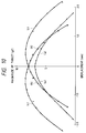
- a curve (a) of Figure 10 shows a relationship between the displacement in the axial direction and the thrust (gf) of the magnet moving body 3 in the case where a sleeve-like magnetic substance at outer circumference of coils is not provided in Figure 9.
- the dimensions and characteristics of the permanent magnet was the same as in Figure 8; the zero displacement was defined as a state in which the midpoint of the magnet moving body 3 coincides with the midpoint of the coil 2B in the middle; and the current flowing through each coil was 40 mA.
- the moving magnet-type actuator includes the magnet moving body formed of a structural body combining the permanent magnets arranged with the same poles thereof confronting each other. Therefore, the magnetic flux density component perpendicular to the direction of magnetization of the permanent magnets (the axial direction) can be increased to a sufficient degree.
- the magnetic flux produced at all the magnetic poles of the permanent magnets can be utilized effectively, a thrust to be produced between the magnetic flux and the current flowing through the three coils wound around the outer circumference of the magnet moving body based on the Fleming's left hand rule can be sufficiently increased. Consequently, a large thrust can be produced by a small structure and a small current.
- the magnet moving body can be made rigid. Consequently, it can be prevent the permanent magnets and the magnetic substance from separating from others, thereby improve the reliability thereof.
- the output extracting pin is provided with the magnet moving body and the pin is slidably supported by the bearing member. This feature contributes to eliminating unnecessary play of the magnet moving body and the output extracting pin and to ensuring the operational stability by permitting the pin to slide smoothly in the axial direction.
- the magnet moving body is formed by fixing the permanent magnets and the magnetic substance interposed between the permanent magnets on the through shaft body that passes through both the permanent magnets and the magnetic substance.
- the permanent magnets and the magnetic substance can be fixed surely on the through shaft body, thus facilitating the assembling work therefor.
- the through shaft body is supported slidably, so that the magnet moving body can move inside the respective coils smoothly without play.
- the ends of the through shaft body can be used as output extracting pins.
- the outer end magnetic substances are provided on both outer ends of the magnet moving body, so that the magnetic flux component perpendicular to the longitudinal direction of the magnet moving body is increased.
- Such magnetic flux component contributes to produce a forth based on the Fleming's left hand rule, so that a much larger thrust can be obtained.
- a force which acts in a direction perpendicular to a direction of the thrust can be made extremely small.
- Figures 11 and 12 show a first embodiment of the invention.
- reference numeral 1 designates a sleeve-like magnetic substance.
- Three coils 2A, 2B, 2C are disposed inside the sleeve-like substance 1 and are secured to the sleeve-like substance 1 by a nonmagnetic member such as a resin that constitutes a nonmagnetic guide sleeve 4 for slidably guiding a magnet moving body 3.
- the magnet moving body 3 includes: two cylindrical rare-earth permanent magnets 5A, 5B arranged with the same poles thereof confronting each other; and a cylindrical magnetic substance 6 that is secured between these permanent magnets 5A, 5B.
- These permanent magnets 5A, 5B and the cylindrical magnetic substance 6 are unified with one another by an adhesive or the like.
- the three coils 2A, 2B, 2C are connected so that current flows in directions different from one another with a zone between the magnetic poles of the permanent magnets 5A, 5B as a boundary. That is, the coil 2B in the middle is arranged so as to enclose both the cylindrical magnetic substance 6 and the end portions of the permanent magnets 5A, 5B including the N-poles; and the coils 2A, 2C on both ends, to enclose the end portions of the permanent magnets 5A, 5B including the S-poles, respectively.
- Thickness of the intermediate magnetic substance 6 disposed between the permanent magnets 5A, 5B is set 0.1 to 1.0 times of the length of the permanent magnets.
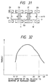
- a high thrust is obtained when an outer diameter of the coil is selected in a range of 1.2 to 3.5 times of a diameter of the permanent magnet, as shown in Figure 32.
- a pin 7 or the like can be attached to the outer end surface of the permanent magnet 5A or 5B as indicated by a phantom line in Figure 1. The pin serves as transmitting a thrust to an external destination as necessary. If this embodiment is used as a vibrator for pocket bells, no pin 7 is required.
- the sleeve-like magnetic substance 1 is arranged on the outer circumference of the respective coils 2A, 2B, 2C.
- a vertical component of the surface magnetic flux density of the magnet moving body 3 is analyzed.
- Figure 13 shows a result obtained from a magnetic field analysis of the vertical component of the surface magnetic flux density made along the longitudinal side surface of two permanent magnets in a case where the two permanent magnets are arranged so that the same poles thereof confront each other while interposing a 1 mm-long magnetic substance therebetween and arranging a sleeve-like magnetic substance facing against the outer circumference of the two permanent magnets.
- Each of the permanent magnets used was a rare-earth permanent magnet whose diameter was 2.5 mm and whose length was 3 mm.
- the sleeve-like magnetic substance enclosed the permanent magnets and was 0.5 mm thick and 10 mm long.
- the sleeve-like magnetic substance was positioned 1.25 mm away from the outer circumference of the permanent magnets. Measurements were made at positions 0.25 to 0.45 mm distant from the surface of the permanent magnets.
- the vertical component of the surface magnetic flux density of the magnet moving body 3 further increases as shown in Figure 13.
- Such an increase allows the magnetic flux component perpendicular to the longitudinal direction of the magnet moving body 3 to increase, such component contributing to producing a thrust based on the Fleming's left hand rule. Therefore, if current is applied to the three coils 2A, 2B, 2C that are wound annularly around the outer circumference of the magnet moving body 3 so that a magnetic field of opposite polarity is generated alternately, then a larger thrust can be produced.
- a thrust F4 of 8.0 was produced when the same power consumption was achieved under the condition that a current of 40 mA was applied to three coils 2A, 2B, 2C while using a magnet moving body formed by interposing a 1 mm-long magnetic substance interposed between two rare-earth permanent magnets as the magnet moving body 3.
- the coils 2A, 2B, 2C were prepared so that the power consumption became the same as in the first and second conventional examples shown in Figures 1 and 2.
- Each of the two permanent magnets was 2.5 mm in diameter and 3 mm in length (the performance of the rare-earth permanent magnet was the same as the one used in the first conventional example).
- the direction of the thrust F4 is such that the magnet moving body 3 moves rightward under the polarity shown in Figure 11.
- the direction of the thrust produced by the magnet moving body 3 is inverted.
- the embodiment functions as a vibrator that repeats vibrating at a predetermined cycle is applicable with applicable to a pocket-bell device.
- a curve (b) of Figure 10 shows a relationship between the axial displacement and the thrust (gf) of the magnet moving body 3 in the case of the first embodiment (the dimensions and arrangement of the permanent magnets and the sleeve-like magnetic substance as well as the characteristics of the permanent magnets are as shown in Figure 13). The relationship refers to a movement of the magnet moving body 3 in the direction of leaving the zero displacement point.
- a curve (c) shows a relationship between the axial displacement and the thrust (gf) of the magnet moving body 3 in the case of the sleeve-like magnetic substance is provided in the first embodiment. The relationship refers to a movement of the magnet moving body 3 in the direction of nearing the zero displacement point.
- the zero displacement was defined as a state in which the midpoint of the magnet moving body 3 coincides with the midpoint of the coil 2B in the middle, and the current flowing in each coil was 40 mA. Accordingly, the reason why the thrusts are different depending on the magnet moving body 3 moving closer to the zero displacement point or moving away from the zero displacement point is that magnet attracting force acts between the magnetic poles of the permanent magnets of the magnet moving body 3 and the sleeve-like magnetic substance 1 so that the magnet moving body 3 returns to the zero displacement point.
- Figure 14 shows a second embodiment of the invention.
- attracting plates 8A, 8B made of a magnetic substance are fitted into and secured to both ends of a sleeve-like magnetic substance 1 and of a nonmagnetic guide sleeve 4.
- a pin secured to an outer end surface of a permanent magnet 5A projects from a hole provided on one attracting plate 8A.
- Other structural aspects of the second embodiment are the same as those of the first embodiment.
- the permanent magnet is attracted by either one of the magnetic attracting plates 8A, 8B when the coils 2A, 2B, 2C are not in conduction. If a thrust is produced in the direction of an arrow R by energizing the coils 2A, 2B, 2C so that a magnetic field of opposite polarity is generated alternately in each of the coils 2A, 2B, 2C with the magnet moving body 3 staying at a position shown in Figure 3, then the magnet moving body 3 moves in the direction of the arrow R by leaving the attracting plate 8A and stops while attracted by the attracting plate 8B.
- the magnet moving body 3 leaves the attracting plate 8B, moves toward the attracting plate 8A, and stops while attracted by this attracting plate 8A.
- the attracting plates 8A, 8B contribute to regulating the range of movement of the magnet moving body 3 accurately.
- the attracting plates 8A, 8B made of a magnetic substance are arranged on both sides of the sleeve-like magnetic substance 1 and the nonmagnetic guide sleeve 4 in the second embodiment, such a structure that the attracting plate is arranged only on one side of the sleeve-like magnetic substance 1 and the nonmagnetic guide sleeve 4 may also be applicable.
- Figures 15 and 16 show a third embodiment of the present invention.
- the magnet moving body 3 includes: two cylindrical rare-earth permanent magnets 5A, 5B arranged with the same poles thereof confronting each other; a cylindrical magnetic substance 6 that is secured between these permanent magnets 5A, 5B and a nonmagnetic sleeve-like holder 7. These permanent magnets 5A; 5B and the magnetic substance 6 are accommodated in the nonmagnetic sleeve-like holder 7 and unified with one another by an adhesive or the like. Other structures are the same as the above mentioned first embodiment.
- the permanent magnets 5A, 5B and the intermediate magnetic substance 6 are accommodated and fixed in the nonmagnetic sleeve-like holder 7.
- This configuration prevents the permanent magnets from being separated from each other due to repulsive force derived from the same poles thereof that confront each other, thus contributing to making the structure of the magnet moving body 3 rigid and improving the reliability thereof while preventing breakage or wear of the permanent magnets. Assembling accuracy can also be improved.
- a magnet moving body 3A includes: two cylindrical rare-earth permanent magnets 5A, 5B arranged with the same poles thereof confronting each other; a cylindrical magnetic substance 6 interposed between these permanent magnets 5A, 5B; nonmagnetic members 9, each having a pin, arranged on the outer end surfaces of the respective permanent magnets; and a nonmagnetic sleeve-like holder 7A.
- the permanent magnets 5A, 5B, the magnetic substance 6, and the disc-like bases of the members 9 with pins are accommodated in the nonmagnetic sleeve-like holder 7A and fixed therein by an adhesive or the like.
- attracting plates 8A, 8B are fitted into and secured to both end portions of a sleeve-like magnetic substance 1 made of a magnetic substance and a nonmagnetic guide sleeve 4.
- the pin portions of the members 9 secured to the outer end surfaces of the permanent magnets 5A, 5B project from holes provided on the attracting plates 8A, 8B.
- the pin portions of the members 9 are slidable through the holes of the attracting plates 8A, 8B.
- Other structural aspects of the fourth embodiment is the same as those of the first embodiment.
- the magnet moving body 3A is attracted by either one of the magnetic attracting plates 8A, 8B when the coils 2A, 2B, 2C are not in conduction. If the magnet moving body 3A is in a shown condition, a thrust is produced in the direction of an arrow R by energizing the coils 2A, 2B, 2C so that a magnetic field of opposite polarity can be generated alternately. As a result, the magnet moving body 3A leaves the attracting plate 8A, moves in the direction of the arrow R, and stops while attracted by the attracting plate 8B.
- the magnet moving body 3A leaves the attracting plate 8B, moves toward the attracting plate 8A, and stops while attracted by the attracting plate 8A. Accordingly, the presence of the attracting plates 8A, 8B contributes to accurately regulating the range of movement of the magnet moving body 3A, thereby allowing the movement of the magnet moving body 3A to be transmitted to an external destination through the members 9 with pins.
- FIG 18 shows a modified example of the magnet moving body applicable to the third embodiment.
- a magnet moving body 3B of this example includes: two cylindrical rare-earth permanent magnets 5A, 5B; a cylindrical magnetic substance 6 interposed between these permanent magnets 5A, 5B; and a nonmagnetic sleeve-like holder 7B.
- the permanent magnets 5A, 5B and the magnetic substance 6 are accommodated in the sleeve-like holder 7B.
- These components constituting the magnet moving body are fixed and integrated with one another by caulking the end portions of the sleeve-like holder 7B. According to this structure, the rate of production of magnet moving bodies can be improved.
- the magnet moving body formed by accommodating the permanent magnets 5A, 5B, the magnetic substance 6, and the disc-like bases of the members 9 with pins, and fixing and integrating these components by caulking the end portions of the sleeve-like holder may be used also in the fourth embodiment.
- the magnetic attracting plates 8A, 8B are arranged on both ends of the sleeve-like magnetic substance 1 and the nonmagnetic guide sleeve 4 and the members 9 with pins are provided on the outer end surfaces of the both permanent magnets 5A, 5B in the fourth embodiment, such a structure that the attracting plate and the member with a pin are provided only on one side of the magnet moving body may also be applied.
- Figures 19 and 20 show a fifth embodiment of the present invention.
- the magnet moving body 3 includes: two cylindrical rare-earth permanent magnets 5A, 5B arranged with the same poles thereof confronting each other; a cylindrical magnetic substance 6 that is secured between these permanent magnets 5A, 5B, and an output extracting pin 9 fixed on outer end surface of the permanent magnets 5A, 5B.
- These permanent magnets 5A, 5B, the magnetic substance 6, and the output extracting pin are integrated with one another by an adhesive or the like.
- the output extracting pin 9 may be either magnetic or nonmagnetic.
- side plates 8A, 8B made of a nonmagnetic substance are fitted into and secured to both ends of the sleeve-like magnetic 1 and the nonmagnetic guide sleeve 4.
- Sleeve-like bearing members 20 made of a metal such as brass, or a highly slidable resin, etc. are supported in the middle of the side plates 8A, 8B, respectively.
- the pin portions 9A of the members 9 with pins which are secured to the outer end surfaces of the permanent magnets 5A, 5B are slidably supported by the inner surfaces of the sleeve-like bearing members 20, with the pin portions 9A projecting from the bearing members.
- the other structures are the same as the above mentioned first embodiment.
- the members 9 with pins integrated with the magnet moving body 3 are slidably supported by the bearing members 20.
- This configuration can regulate the magnet moving body 3 so as to be concentric with the central axis of the nonmagnetic guide sleeve 4 at all times, thus preventing unnecessary play of the magnet moving body 3 as well as the members 9 with pins.
- the magnet moving body 3 is not brought into contact with the inner circumferential surface of the magnetic guide sleeve 4, so that the magnet moving body 3 can move smoothly in the axial direction, which in turn eliminates, e.g., wear of the magnet moving body 3 and the nonmagnetic guide sleeve 4.
- Figure 21 shows a modified example of the magnet moving body used in the fifth embodiment.
- a magnet moving body 3A is formed by interposing a cylindrical magnetic substance 6 between two permanent magnets 5A, 5B with the same poles of the permanent magnets confronting each other, accommodating these components in a nonmagnetic sleeve-like holder 7, arranging members 9 with output extracting pins on outer end surfaces of the permanent magnets 5A, 5B, and fixing disc-like bases 9B of such members 9 with pins on both end portions of the sleeve-like holder 7.
- the permanent magnets 5A, 5B, the cylindrical magnetic substance 6, and the members 9 with pins may be fixed on the sleeve-like holder 7 by an adhesive or the like, or by caulking the end portions of the sleeve-like holder 7.
- the side plates 8A, 8B may be made of a magnetic material so that the side plates can function as the attracting plates.
- the magnet moving body 3 is attracted by either one of the magnetic side plates 8A, 8B when the coils 2A, 2B, 2C are not in conduction. If a thrust is produced at the coils 2A, 2B, 2C in the direction of the magnet moving body 3 leaving the side plate by which the magnet moving body 3 is attracted, then the magnet moving body 3 moves toward the opposite side plate and stops while attracted by such opposite side plate.
- magnet moving body 3 including two permanent magnets arranged with the same poles thereof confronting each other and the magnetic substance interposed therebetween
- a magnet moving body such as including three or more permanent magnets with the same poles thereof confronting each other and magnetic substances interposed therebetween may be applicable.
- the number of coils can be increased to four or more to match the increase in the number of permanent magnets.
- the member 9 with a pin may be arranged only on one side thereof.
- the bearing member is provided only on one side (the length of the bearing member 20 is preferably longer in this case).
- Figures 22A and 22B show a sixth embodiment of the present invention.
- the magnet moving body 3 includes: two cylindrical rare-earth permanent magnets 5A, 5B arranged with the same poles thereof confronting each other; a cylindrical intermediate magnetic substance 6A that is secured between these permanent magnets 5A, 5B; and cylindrical outer end magnetic substances 6B, 6C secured to the outer end surfaces of the permanent magnets 5A, 5B.
- These permanent magnets 5A, 5B and the magnetic substances 6A, 6B, 6C are integrated with one another by an adhesive or the like.
- a thickness of the outer end magnetic substances are designed about half to same (1/2 to 1) of that of the intermediate magnetic substance 6A.
- the other structures are the same as the above mentioned first embodiment.
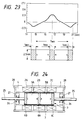
- Figure 23 shows a result obtained from a magnetic field analysis of the vertical component of the surface magnetic flux density made along the longitudinal side surface of two permanent magnets when the two permanent magnets were arranged so that the same poles thereof confront each other while interposing the magnetic substance between the permanent magnets and disposing magnetic substances on outer end surfaces of the permanent magnets.
- the structure of the magnet moving body 3 in Figure 23 is such that the two permanent magnets are arranged so that the same poles thereof confront each other; the intermediate magnetic substance is interposed between the permanent magnets; and the outer end magnetic substances are arranged on the outer end surfaces of the permanent magnets as shown in Figure 23.
- the vertical component of the surface magnetic flux density in an area corresponding to the positions of the outer end magnetic substances in the case of Figure 23 is better than in the case of Figure 8 in which no outer end magnetic substances are used (it goes without saying that the vertical component of the surface magnetic flux density is better than in the case of Figure 3 in which only one permanent magnet is used.)
- the magnetic moving body 3 formed by arranging the two permanent magnets 5A, 5B with the same poles thereof confronting each other, interposing the intermediate magnetic substance 6A between the permanent magnets 5A, 5B, and arranging the outer end magnetic substances 6B, 6C on the outer end surfaces of the permanent magnets 5A, 5B can further increase the magnetic flux component perpendicular to the longitudinal direction of the magnet moving body 3, such magnetic flux component contributing to producing a thrust based on the Fleming's left hand rule.
- An output extracting pin 7 may be arranged on the outer end magnetic substance 6B or 6C as shown by a phantom line of Figure 22A so that the thrust can be transmitted to an external destination. In the case where the embodiment is used as a vibrator for a pocket bell or the like, no pin 7 is required.
- a magnetic attracting plate or plates 8 may be fixed on either one or both end portions of the sleeve-like magnetic substance 1 as shown by a phantom line of Figure 22a so that the range of movement of the magnet moving body 3 can be regulated. In this case, the magnet moving body 3 stops while attracted by the magnetic attracting plate 8.
- Figure 24 shows a seventh embodiment of the invention.
- a magnet moving body 3 accommodates two cylindrical rare-earth permanent magnets 5A, 5B, a cylindrical intermediate magnetic substance 6A interposed between these permanent magnets 5A, 5B, and cylindrical outer end magnetic substances 6B, 6C arranged on outer end surfaces of the permanent magnets 5A, 5B in a nonmagnetic sleeve-like holder 7. These components are integrated with one another by caulking the end portions of the holder 7, by being bonded to the holder 7, or like means.
- Nonmagnetic pins 25 are integrally formed on the outer end magnetic substances 6B, 6C of the magnet moving body 3.
- the nonmagnetic pins 25 are firmly integrated with the flat cylindrical outer end magnetic substances 6B, 6C in the middle thereof by welding, bonding, or like means.
- support plates 28 are secured to both end portions of a sleeve-like magnetic substance 1 and a nonmagnetic guide sleeve 4.
- the nonmagnetic pins 25 pass through central holes of the support plates 28.
- Both nonmagnetic pins 25 are slidably supported by the central holes 26.
- Annular permanent magnets 27 are fixed on the inner surfaces of the support plates 28, respectively, so that repulsive force can be produced between the magnetic poles of the annular permanent magnets 28 and the magnetic poles on the outer end surfaces of the permanent magnets 5A, 5B.
- the S-poles of the outer end surfaces of the permanent magnets 5A, 5B confront the S-poles of the annular permanent magnets 27.
- Other configurational aspects of the this embodiment are the same as those of the sixth embodiment.
- the magnet moving body 3 is positioned to the middle of the sleeve-like magnetic substance 1 because of the repulsive force derived from the permanent magnets 5A, 5B and the annular permanent magnets 27 on right and left when the coils 2A, 2B, 2C are not energized.
- the magnet moving body 23 is driven to one side.
- alternating current is applied to the coils, the magnet moving body 23 functions as a vibrator by the reciprocating operation thereof.
- the magnet moving body 3 is made to return to the middle position by the repulsive force derived from the permanent magnets 5A, 5B and the annular permanent magnets 27 on right and left.
- Figure 25 shows an eighth embodiment of the invention.
- the outer end magnetic substances 6B, 6C of the magnet moving body 3 are provided with pins (the pines may be made of either a nonmagnetic or magnetic substance) 25A so as to be integral with one another. That is, the pins 25A are secured to and integrated with the central portions of the outer end magnetic substances 6B, 6C by welding, bonding, or like means, or unitized with the outer end magnetic substances themselves.
- support plates 28 are secured to both end portions of a sleeve-like magnetic substance 1 and a nonmagnetic guide sleeve 4, and the pins 25A pass through central holes 26 of the support plates 28. Both pins 25A are slidably supported by the central holes 26.
- Compression springs 29 are interposed between the outer end magnetic substances 6B, 6C and the inner surfaces of the support plates 28, respectively.
- Other configurational aspects of this embodiment are the same as those of the seventh embodiment.
- the magnet moving body 3 is returned to the middle position of the sleeve-like magnetic substance 1 by the resilient force of the compression spring 29 on right and left when the coils 2A, 2B, 2C are not energized, whereas the magnet moving body 3 is driven to one side by applying direct current to the coils 2A, 2B, 2C.
- the magnet moving body 3 functions as a vibrator by the reciprocating operation thereof.
- the magnet moving body 3 is made to return to the middle position by the resilient force of the compression springs 29. As a result, noise due to collision of the magnet moving body 3 against the support plates 28 can be prevented.
- Figures 26 and 27 show a ninth embodiment.
- reference numeral 1 designates a sleeve-like magnetic substance.
- Three coils 2A, 2B, 2C are arranged inside the sleeve-like magnetic substance 1 and are secured to the sleeve-like substance 1 by a nonmagnetic member such as an insulating resin that constitutes a nonmagnetic guide sleeve 4 for slidably guiding a magnet moving body 3.
- the inner surface of the nonmagnetic guide sleeve 4 forms an inner circumferential surface.
- the magnet moving body 3 includes: two hollow cylindrical rare-earth permanent magnets 5A, 5B arranged with the same poles thereof confronting each other; a hollow cylindrical intermediate magnetic substance 6 interposed between these permanent magnets 5A, 5B; and hollow disc-like cushion plates 7A, 7B arranged on the outer end surfaces of the permanent magnets 5A, 5B with a through shaft body 8 made of a metal being inserted therethrough.
- the through shaft body 8 is held by causing clampers (E rings made of a metal) 20 to be fitted into fitting grooves 9 of the through shaft body 8, so that the permanent magnets 5A, 5B, the intermediate magnetic substance 6, and the disc-like cushion plates 7A, 7B are fixed on the metallic through shaft body 8.
- the through shaft body 8 is made of either a nonmagnetic or magnetic metal.
- the cushion plates 7A, 7B are made of an elastic material such as silicon rubber, and are interposed between a pair of clampers 20 while compressed slightly. As a result, the cushion plates 7A, 7B can absorb variations in the thickness of the respective permanent magnets 5A, 5B and the magnetic substance 6, thereby preventing play of these components.
- An adhesive may additionally be used to integrate the metallic through shaft body 8 with the permanent magnets 5A, 5B and the magnetic substance 6.
- the three coils 2A, 2B, 2C are connected so that current flows in different directions with a zone between the magnetic poles of the permanent magnets 5A, 5B as a boundary. That is, the coil 2B in the middle is wound annularly so that both the magnetic substance 6 and the end portions of the permanent magnets 5A, 5B including the N-poles are enclosed; whereas the coils 2A, 2C on both ends are wound annularly so that the end portions of the permanent magnets 5A, 5B including the S-poles are enclosed.
- the direction of the current flowing through the coil 2B in the middle opposes the direction of current flowing through the coils 2A, 2C on both ends (see N and S indicated in each coil in Figure 26).
- side plates 21A, 21B made of a nonmagnetic substance are fitted into and secured to both ends of the sleeve-like magnetic substance 1 and the nonmagnetic guide sleeve 4.
- Sleeve-like bearing members 22 made of a sintered metal, a highly slidable resin or the like are supported in the middle of the side plates 21A, 21B, respectively.
- the through shaft body 8 passing through and integrated with the permanent magnets 5A, 5B and the magnetic substance 6 is slidably supported by the inner surfaces of the sleeve-like bearing members 22.
- One end of the through shaft body 8 projects from the bearing member so that such end can be used as an output pin.
- the side plates 21A, 21B have projecting portions 23 that are fitted into the inner circumferential surfaces of the nonmagnetic guide sleeve 4, so that the front ends of the projecting portions 23 can regulate the range of movement of the magnet moving body 3 while abutting against the cushion plates 7A, 7B when the magnet moving body 3 is moving.
- the bearing members 22 may be either nonmagnetic or magnetic.
- the magnet moving body 3 is formed by inserting the metallic through shaft body 8 into the hollow cylindrical rare-earth permanent magnets 5A, 5B, the hollow cylindrical intermediate magnetic body 6, and the hollow disc-like cushion plates 7A, 7B; and fitting the fasteners 20 into the fitting grooves 9 of the metallic through shaft body 8 for holding.
- the permanent magnets 5A, 5B and the intermediate magnetic body 6 can be fixed and integrated with one another reliably, which facilitates the assembling work therefor.
- the through shaft body 8 integrated with the magnet moving body 3 is slidably supported by the bearing members 22.
- This configuration can regulate the magnet moving body 3 so as to be concentric with the central axis of the nonmagnetic guide sleeve 4 at all times without allowing the magnet moving body 3 to play.
- the gap between the outer circumference of the permanent magnets 5A, 5B and the coils 2A, 2B, 2C can be set to a necessary minimum without having to cover a holder or the like on the outer circumference of the permanent magnets for the integration of the permanent magnets 5A, 5B and the magnetic body 6, thereby contributing to effectively improving the thrust.
- the magnet moving body 3 is not brought into contact with the inner circumferential surface of the nonmagnetic guide sleeve 4, so that the magnet moving body 3 can move smoothly in the axial direction, which in turn eliminates, e.g., wear of the magnet moving body 3 and the nonmagnetic guide sleeve 4.
- the side plate or plates formed of the magnetic substance can serve as a magnet attracting body that attracts the magnet moving body 3.
- both of the side plates 21A, 21B are made of a magnetic substance
- the magnet moving body 3 is attracted and held by either one of the side plates when the coils 2A, 2B, 2C are not energized. If a thrust is produced by the coils 2A, 2B, 2C so that the magnet moving body 3 moves to leave the side plate by which the magnet moving body 3 is attracted, then the magnet moving body 3 moves to the opposite side plate and stops while attracted by such opposite side plate.
- the side plates can be set so that the magnet moving body 3 is attracted and held by such one of the side plates at all times.
- Figure 28 shows a tenth embodiment of the invention.
- nonmagnetic side plates 21C, 21D are fitted into and secured to both ends of a sleeve-like magnetic substance 1 and of a nonmagnetic guide sleeve 4.
- Compression springs 24 are arranged between the inner surfaces of the side plates 21C, 21D and the disc-like cushion plates 7A, 7B on the sides of the magnet moving body 3. The compression springs 24 bias the magnet moving body 3 back to the middle position.
- Other configurational aspects of the tenth embodiment are the same as those of the ninth embodiment.
- the magnet moving body 3 is returned to the middle position of the sleeve-like magnetic substance 1 because of the resilient force of the compression springs 24 on right and left when the coils 2A, 2B, 2C are not energized.
- the magnet moving body 3 is driven to one side.
- alternating current is applied to the coils, the magnet moving body 3 functions as a vibrator by the reciprocating operation thereof.
- the magnet moving body 3 is made to return to the middle position by the resilient force of the compression springs 24. As a result, noise due to collision of the magnet moving body 23 against the side plates 21C, 21D can be prevented.
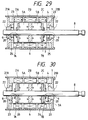
- Figure 29 shows an eleventh embodiment of the invention.
- nonmagnetic side plates 21A, 21B are fitted into and secured to both ends of a sleeve-like magnetic substance 1 and of a nonmagnetic guide sleeve 4.
- Annular permanent magnets 25 for returning the magnet moving body 3 are fixed on the inner circumferences of the projecting portions 23 of the side plates 21A, 21B.
- the through shaft body 8 of the magnet moving body 3 passes through inner circumferential holes of the return annular permanent magnets 25 and the bearing members 22.
- the return annular permanent magnets 25 have, on the surfaces confronting the magnet moving body 3, magnetic poles that generate repulsive force relative to the magnetic poles on the outer ends of the permanent magnets 5A, 5B of the magnet moving body 3.
- the S-poles on the outer sides of the permanent magnets 5A, 5B confront the S-poles of the return annular permanent magnets 25.
- Other configurational aspects of the eleventh embodiment are the same as those of the ninth embodiment.
- the magnet moving body 3 is returned to the middle position in the sleeve-like magnetic substance 1 because of the resilient force of the return annular permanent magnets 25 on right and left when the coils 2A, 2B, 2C are not in conduction.
- the magnet moving body 3 can be driven to one side.
- alternating current is applied to the coils, the magnet moving body 3 functions as a vibrator by the reciprocating operation thereof.
- the magnet moving body 3 is made to return to the middle position by the resilient force of the return annular permanent magnets 25.
- noise due to collision of the magnet moving body 3 against the side plates 21A, 21B and the annular permanent magnets 25 can be prevented.
- Figure 30 shows a twelfth embodiment of the invention.
- a magnet moving body 3 includes: two hollow cylindrical rare-earth permanent magnets 5A, 5B arranged with the same poles thereof confronting each other; a hollow cylindrical intermediate magnetic substance 6 interposed between these permanent magnets 5A, 5B; hollow disc-like outer end magnetic substances 26 arranged on the outer sides of the permanent magnets 5A, 5B; and hollow disc-like cushion plates 7A, 7B arranged on the outer sides of the outer end magnetic substances 26 with a through shaft body 8 made of a metal being inserted therethrough.
- the through shaft body 8 is held by causing clampers (E rings made of a metal) 20 to be fitted into fitting grooves 9 of the through shaft body 8, so that the permanent magnets 5A, 5B, the intermediate magnetic substance 6, the outer end magnetic substances 26, and the disc-like cushion plates 7A, 7B are fixed on the metallic through shaft body 8.
- the through shaft body 8 is made of either a nonmagnetic or magnetic metal.
- the cushion plates 7A, 7B are made of an elastic material such as silicon rubber, and are interposed between a pair of fasteners 20 while compressed slightly. As a result, the cushion plates 7A, 7B can absorb variations in the thickness of the respective permanent magnets 5A, 5B and the magnetic substances 6, 26, thereby preventing play of these components.
- An adhesive may additionally be used for integrating the metallic through shaft body 8 with the permanent magnets 5A, 5B and the magnetic substance 6.
- the thickness of each outer end magnetic substance 26 is designed about half or same (50 to 100%) of the intermediate magnetic substance 6.
- Other configurational aspects of this embodiment are the same as those of the ninth embodiment.
- the magnetic flux radiated from the magnetic poles on the outer end surfaces of the permanent magnets 5A, 5B are easy to bend perpendicularly due to the presence of the outer end magnetic substances 26.
- the vertical component of the magnetic flux density (the component perpendicular to the axial direction of the permanent magnets) in the outer side portion of the permanent magnets 5A, 5B increases. That is, the magnetic flux density perpendicular to the longitudinal direction of the magnet moving body 3A which contributes to producing a thrust to be produced based on the Fleming's left hand rule can be increased.
- a still larger thrust can be produced by applying current to the three coils 2A, 2B, 2C wound annularly around the magnet moving body 3 so that a magnetic field of opposite polarity can be generated alternately.
- a magnetic field of opposite polarity can be generated alternately.
- an improvement in thrust by up to 10% or so can be obtained compared with the ninth embodiment involving no outer end magnetic substances.
- the magnet moving body 3 formed of the two permanent magnets arranged with the same poles thereof confronting each other and the magnetic substance interposed therebetween has been exemplified in the ninth to eleventh embodiments, the magnet moving body may be formed of three or more permanent magnets with the same poles thereof confronting each other and magnetic substances interposed therebetween. In this case, the number of coils can be increased to four or more to match the increase in the number of permanent magnets.
- the magnet moving body 3 formed of the two permanent magnets arranged with the same poles thereof confronting each other, the intermediate soft magnetic substance interposed therebetween, and the outer end magnetic substances arranged on the outer sides of the two permanent magnets
- the magnet moving body may be formed of three or more permanent magnets with the same poles thereof confronting each other and magnetic substances interposed therebetween.
- the number of coils can be increased to four or more to match the increase in the number of permanent magnets.
- the compression springs 24 or the annular permanent magnets 25 for biasing the magnet moving body back to the middle position as described in the tenth and eleventh embodiments may, of course, be arranged.
- both ends of the through shaft body of the magnet moving bodies 3, 3A are supported by the bearings in the ninth to twelfth embodiments, such a structure that only one side of the through shaft body may be supported by the bearing may be applicable. In this case, only one bearing is used (however, it is desirable to use a longer bearing member).
- the magnet moving body formed of the two permanent magnets arranged with the same poles thereof confronting each other and the magnetic substance interposed therebetween
- the magnet moving body may be formed of three or more permanent magnets with the same poles thereof confronting each other and magnetic substances interposed therebetween as shown in Figure 31.
- the number of coils can be increased to four or more to match the increase in the number of permanent magnets.
- each coil may be wound around the outer circumference of the magnet moving body as in the other cases.
- the moving magnet-type actuator of the invention is characterized as forming a magnet moving body by interposing a magnetic substance between at least two permanent magnets, the same poles of the permanent magnets confronting each other.
- a magnetic flux component perpendicular to the longitudinal direction of the magnet moving body (the direction in which the permanent magnets are magnetized) can be sufficiently increased.
- the moving magnet-type actuator capable of providing a large thrust by a small structure and a small current can be achieved.
- the moving magnet-type actuator of the device is characterized as forming a magnet moving body by interposing a magnetic substance between at least two permanent magnets with the same poles of the permanent magnets confronting each other, and by accommodating and fixing these components in a nonmagnetic sleeve-like holder.
- the magnet moving body is made into a rigid structural body with improved wear resistance.
- the magnet moving body has a feature that the output extracting pin is arranged on one side thereof, so that the movement of the magnet moving body can be made smooth by supporting the pin with the bearing member that maintains a predetermined positional relationship with respect to the three coils.
- the moving magnet-type actuator of the invention is characterized as forming a magnet moving body by interposing an intermediate magnetic substance between at least two permanent magnets with the same poles of the permanent magnets confronting each other, and by arranging outer end magnetic substances on the outer end surfaces of the permanent magnets.
- This configuration contributes to sufficiently increasing a magnetic flux component perpendicular to the longitudinal direction of the magnet moving body (the direction in which the permanent magnets are magnetized), such component being derived not only from the portion at which the same poles of the permanent magnets confront each other, but also from the outer end portions of the permanent magnets.
- the moving magnet-type actuator capable of providing a large thrust by a small structure and a small current can be achieved.
- the moving magnet-type actuator of the device is characterized as forming a magnet moving body by interposing an intermediate magnetic substance between at least two permanent magnets and integrating these components with a through shaft body, the same poles of the two permanent magnets confronting each other and the through shaft body being supported slidably by bearing members.
- a magnetic flux component perpendicular to the longitudinal direction of the magnet moving body (the direction in which the permanent magnets are magnetized) can be sufficiently increased.
- the through shaft body allows a plurality of permanent magnets and intermediate magnetic substances to be fixed surely, thus making the magnet moving body rigid and facilitating the assembling work therefor.
- the use of the through shaft body also dispenses with a nonmagnetic holder or the like for covering the outer circumference of the permanent magnets and the intermediate magnetic substance for their integration, thereby contributing to a further improvement of thrust while decreasing the gap between the outer circumference of the permanent magnets and the respective coils. Still further, by supporting the through shaft body functioning as an output extracting pin of the magnet moving body with the bearing members that maintain a predetermined positional relationship with respect to the three coils, the magnet moving body can move smoothly. Consequently, a highly reliable moving magnet-type actuator that can produce a large thrust by a small structure and a small current can be achieved.
Landscapes
- Engineering & Computer Science (AREA)
- Power Engineering (AREA)
- Reciprocating, Oscillating Or Vibrating Motors (AREA)
Applications Claiming Priority (10)
| Application Number | Priority Date | Filing Date | Title |
|---|---|---|---|
| JP83991/92 | 1992-04-06 | ||
| JP21326792A JP3302727B2 (ja) | 1992-07-20 | 1992-07-20 | 可動磁石式アクチュエータ |
| JP213267/92 | 1992-07-20 | ||
| JP83992/92 | 1992-11-12 | ||
| JP1992083992U JP2595510Y2 (ja) | 1992-11-12 | 1992-11-12 | 可動磁石式アクチュエータ |
| JP1992083991U JP2595509Y2 (ja) | 1992-11-12 | 1992-11-12 | 可動磁石式アクチュエータ |
| JP12035493A JP3302777B2 (ja) | 1993-04-26 | 1993-04-26 | 可動磁石式アクチュエータ |
| JP120354/93 | 1993-04-26 | ||
| JP35519/93 | 1993-06-07 | ||
| JP1993035519U JP2596857Y2 (ja) | 1993-06-07 | 1993-06-07 | 可動磁石式アクチュエータ |
Publications (2)
| Publication Number | Publication Date |
|---|---|
| EP0580117A2 true EP0580117A2 (fr) | 1994-01-26 |
| EP0580117A3 EP0580117A3 (en) | 1994-08-24 |
Family
ID=27521707
Family Applications (1)
| Application Number | Title | Priority Date | Filing Date |
|---|---|---|---|
| EP9393111583A Withdrawn EP0580117A3 (en) | 1992-07-20 | 1993-07-20 | Moving magnet-type actuator |
Country Status (2)
| Country | Link |
|---|---|
| US (1) | US5434549A (fr) |
| EP (1) | EP0580117A3 (fr) |
Cited By (32)
| Publication number | Priority date | Publication date | Assignee | Title |
|---|---|---|---|---|
| WO1995031851A1 (fr) * | 1994-05-18 | 1995-11-23 | Huntleigh Technology Plc | Organe de commande magnetique lineaire |
| EP1001512A2 (fr) * | 1998-11-10 | 2000-05-17 | Asm Lithography B.V. | Actionneur et transducteur |
| EP0955645A3 (fr) * | 1998-05-06 | 2000-08-16 | O.M.T. Officine Meccaniche Torino S.p.A. | Actionneur électromagnétique ultrarapide sans ressorts |
| WO2001039588A1 (fr) * | 1999-12-06 | 2001-06-07 | Macrosonix Corporation | Moteur a reluctance a force dynamique de grande stabilite |
| WO2002091551A1 (fr) * | 2001-05-08 | 2002-11-14 | Staf Corporation | Appareil d'entrainement magnetique |
| EP1248725A4 (fr) * | 1999-12-08 | 2003-01-15 | California Linear Devices Inc | Procede de fabrication d'un assemblage empile de stator destine a un moteur lineaire |
| WO2002056447A3 (fr) * | 2000-12-26 | 2003-03-06 | Bei Technologies Inc | Moteur lineaire sans balais a courant continu comprenant un ensemble induit sans fer |
| DE10216421A1 (de) * | 2002-04-12 | 2003-10-30 | Forschungszentrum Juelich Gmbh | Magnetführungseinrichtung |
| WO2004071793A1 (fr) * | 2003-02-17 | 2004-08-26 | Bayerische Motoren Werke | Suspension active de vehicule, a moteur lineaire |
| FR2852163A1 (fr) * | 2003-02-28 | 2004-09-10 | Denso Corp | Unite de deplacement de fluide et systeme de transport de chaleur |
| EP1101273A4 (fr) * | 1998-07-24 | 2005-01-26 | Guitammer Company | Vibreur basse frequence |
| DE102005049620A1 (de) * | 2005-10-16 | 2007-05-03 | Günter Biechele | Schwingantrieb |
| US7315098B2 (en) | 2001-03-27 | 2008-01-01 | Matsushita Electric Works, Ltd. | Linear oscillator and electrically driven toothbrush |
| WO2009050500A1 (fr) * | 2007-10-16 | 2009-04-23 | Sheppard & Charnley Limited | Solénoïde |
| CN102395432A (zh) * | 2009-04-15 | 2012-03-28 | Thk株式会社 | 线性电动机致动器 |
| EP2362530A3 (fr) * | 2010-02-26 | 2012-11-07 | Karl Storz GmbH & Co. KG | Moteur linéaire doté d'une auto-alimentation à aimant permanent |
| CN102844972A (zh) * | 2010-03-25 | 2012-12-26 | 克劳迪奥·拉斯特鲁奇 | 具有可动磁体的机电转换系统;包括所述系统和产生声波的可动构件的声扩散器 |
| FR2984634A1 (fr) * | 2011-12-19 | 2013-06-21 | Univ Paris Curie | Actionneur vitrotactile lineaire miniature |
| CN102025253B (zh) * | 2009-09-15 | 2013-11-13 | 台达电子工业股份有限公司 | 磁性振动器 |
| EP1637009B1 (fr) * | 2003-06-26 | 2014-09-17 | MED-EL Elektromedizinische Geräte GmbH | Systeme et procede permettant de diminuer l'effet des champs magnetiques sur un transducteur magnetique |
| US8884473B2 (en) | 2008-11-18 | 2014-11-11 | Hitachi Metals, Ltd. | Mover, armature, and linear motor |
| US8912692B2 (en) | 2009-09-02 | 2014-12-16 | Delta Electronics, Inc. | Magnetic vibrator with inclined pole pieces |
| EP2846445A4 (fr) * | 2012-05-02 | 2016-06-22 | Mitsubishi Electric Eng | Générateur électrique à vibration |
| CN105703593A (zh) * | 2015-09-23 | 2016-06-22 | 歌尔声学股份有限公司 | 线性振动马达 |
| EP1835602B1 (fr) * | 2006-03-13 | 2016-08-10 | Woodward Governor Company | Actionneur magnétique en mouvement avec collier d'ensouple à denture et course d'armature asymétrique |
| WO2017009017A1 (fr) | 2015-07-16 | 2017-01-19 | Lofelt Gmbh | Actionneur vibrant |
| EP2245723B1 (fr) * | 2008-01-25 | 2017-11-08 | J. Dams Beheer B.V. | Actionneur magnetique |
| US10270326B2 (en) | 2014-07-28 | 2019-04-23 | Nidec Copal Corporation | Linear vibration motor |
| US10424999B2 (en) | 2014-07-28 | 2019-09-24 | Nidec Copal Corporation | Linear vibration motor |
| WO2021052862A1 (fr) * | 2019-09-17 | 2021-03-25 | nui lab GmbH | Actionneur électromagnétique |
| WO2021115585A1 (fr) | 2019-12-11 | 2021-06-17 | Lofelt Gmbh | Actionneur à vibration linéaire ayant une bobine et un aimant mobiles |
| WO2023144045A1 (fr) * | 2022-01-25 | 2023-08-03 | Robert Bosch Gmbh | Procédés, matériaux et structures pour fabriquer un dispositif excitateur à actionnement magnétique à l'aide d'une impression 3d |
Families Citing this family (211)
| Publication number | Priority date | Publication date | Assignee | Title |
|---|---|---|---|---|
| US6437771B1 (en) * | 1995-01-18 | 2002-08-20 | Immersion Corporation | Force feedback device including flexure member between actuator and user object |
| US5661446A (en) * | 1995-06-07 | 1997-08-26 | Mts Systems Corporation | Electromagnetic actuator |
| US6836201B1 (en) * | 1995-12-01 | 2004-12-28 | Raytheon Company | Electrically driven bistable mechanical actuator |
| SE509905C2 (sv) * | 1995-12-22 | 1999-03-22 | Electrolux Ab | Solenoid |
| US5767402A (en) * | 1996-03-07 | 1998-06-16 | Mts Systems Corporation | Material testing system having DC brushless linear motor |
| US5644279A (en) * | 1996-04-03 | 1997-07-01 | Micron Technology, Inc. | Actuator assembly |
| US5809157A (en) * | 1996-04-09 | 1998-09-15 | Victor Lavrov | Electromagnetic linear drive |
| US5815057A (en) * | 1996-05-17 | 1998-09-29 | K & L Microwave Incorporated | Electronically controlled switching device |
| US6466119B1 (en) * | 1996-09-06 | 2002-10-15 | Chester Drew | Magnetic circuit |
| US5821841A (en) * | 1997-03-18 | 1998-10-13 | Eastman Kodak Company | Microceramic linear actuator |
| US6040752A (en) * | 1997-04-22 | 2000-03-21 | Fisher; Jack E. | Fail-safe actuator with two permanent magnets |
| US5961045A (en) * | 1997-09-25 | 1999-10-05 | Caterpillar Inc. | Control valve having a solenoid with a permanent magnet for a fuel injector |
| US5896076A (en) * | 1997-12-29 | 1999-04-20 | Motran Ind Inc | Force actuator with dual magnetic operation |
| DE19832244C2 (de) * | 1998-07-17 | 2000-10-19 | Rollei Fototechnic Gmbh | Elektromagnetischer Antrieb für einen Schlitzverschluß |
| US7561142B2 (en) * | 1999-07-01 | 2009-07-14 | Immersion Corporation | Vibrotactile haptic feedback devices |
| US8169402B2 (en) * | 1999-07-01 | 2012-05-01 | Immersion Corporation | Vibrotactile haptic feedback devices |
| US6501357B2 (en) * | 2000-03-16 | 2002-12-31 | Quizix, Inc. | Permanent magnet actuator mechanism |
| US6966760B1 (en) | 2000-03-17 | 2005-11-22 | Brp Us Inc. | Reciprocating fluid pump employing reversing polarity motor |
| JP3591429B2 (ja) * | 2000-06-22 | 2004-11-17 | オムロンヘルスケア株式会社 | 流量コントロール弁及び血圧計 |
| DE60140255D1 (de) * | 2000-08-03 | 2009-12-03 | Direct Thrust Designs Ltd | Elektrischer antrieb mit kurzem hub |
| US7084854B1 (en) | 2000-09-28 | 2006-08-01 | Immersion Corporation | Actuator for providing tactile sensations and device for directional tactile sensations |
| US6873067B2 (en) * | 2000-09-29 | 2005-03-29 | Matsushita Electric Works, Ltd. | Linear oscillator |
| US7066915B2 (en) * | 2001-04-10 | 2006-06-27 | Medtronic, Inc. | Low profile inlet valve for a piston pump therapeutic substance delivery device |
| ATE369885T1 (de) * | 2001-04-10 | 2007-09-15 | Medtronic Inc | Flachprofiliges einlassventil für ein auf einer kolbenpumpe basiertes gerät zum zuführen eines medizinischen stoffes |
| US7288085B2 (en) | 2001-04-10 | 2007-10-30 | Medtronic, Inc. | Permanent magnet solenoid pump for an implantable therapeutic substance delivery device |
| US7201746B2 (en) * | 2001-04-10 | 2007-04-10 | Medtronic, Inc. | Implantable therapeutic substance delivery device having a piston pump with an anti-cavitation valve |
| US6639496B1 (en) * | 2001-04-25 | 2003-10-28 | Van Namen Frederik T. | Bistable long-stroke electro-magnetic mechanical actuator |
| US6512435B2 (en) * | 2001-04-25 | 2003-01-28 | Charles Willard | Bistable electro-magnetic mechanical actuator |
| ATE485766T1 (de) * | 2001-06-12 | 2010-11-15 | Pelikan Technologies Inc | Elektrisches betätigungselement für eine lanzette |
| US20030037765A1 (en) * | 2001-08-24 | 2003-02-27 | Shafer Scott F. | Linear control valve for controlling a fuel injector and engine compression release brake actuator and engine using same |
| US7623114B2 (en) | 2001-10-09 | 2009-11-24 | Immersion Corporation | Haptic feedback sensations based on audio output from computer devices |
| JP3863429B2 (ja) * | 2002-01-04 | 2006-12-27 | 学校法人東京電機大学 | リニア振動アクチュエータ |
| US9295425B2 (en) | 2002-04-01 | 2016-03-29 | Med-El Elektromedizinische Geraete Gmbh | Transducer for stapedius monitoring |
| US7190247B2 (en) * | 2002-04-01 | 2007-03-13 | Med-El Elektromedizinische Geraete Gmbh | System and method for reducing effect of magnetic fields on a magnetic transducer |
| US6936937B2 (en) * | 2002-06-14 | 2005-08-30 | Sunyen Co., Ltd. | Linear electric generator having an improved magnet and coil structure, and method of manufacture |
| EP1378986A1 (fr) * | 2002-07-02 | 2004-01-07 | Nti Ag | Actionneur à force constante |
| US7004446B2 (en) | 2002-09-16 | 2006-02-28 | Petro John P | Bistable dual-magnet valve unit |
| US7570261B1 (en) * | 2003-03-06 | 2009-08-04 | Xdyne, Inc. | Apparatus and method for creating a virtual three-dimensional environment, and method of generating revenue therefrom |
| US7378763B2 (en) * | 2003-03-10 | 2008-05-27 | Höganäs Ab | Linear motor |
| JP4155101B2 (ja) * | 2003-05-16 | 2008-09-24 | 松下電工株式会社 | 振動型リニアアクチュエータ及びそれを用いた電動歯ブラシ |
| JP4218413B2 (ja) * | 2003-05-16 | 2009-02-04 | パナソニック電工株式会社 | 振動、ローリング駆動両用リニアアクチュエータ及びそれを用いた電動歯ブラシ |
| US6956308B2 (en) * | 2003-07-15 | 2005-10-18 | Nikon Corporation | Dual flow circulation system for a mover |
| US7355308B2 (en) * | 2003-08-21 | 2008-04-08 | Nikon Corporation | Mover combination with two circulation flows |
| US7280020B2 (en) * | 2004-02-25 | 2007-10-09 | General Motors Corporation | Magnetic inertial force generator |
| US7319374B2 (en) * | 2004-04-14 | 2008-01-15 | Immersion Corporation | Moving magnet actuator |
| US7378765B2 (en) * | 2004-08-09 | 2008-05-27 | Oriental Motor Co., Ltd. | Cylinder-type linear motor and moving part thereof |
| JP4725910B2 (ja) * | 2004-09-07 | 2011-07-13 | 日本パルスモーター株式会社 | リニアアクチュエータ |
| JP4860625B2 (ja) | 2004-10-08 | 2012-01-25 | イマージョン コーポレーション | タッチ式入力装置におけるボタンおよびスクロール動作シミュレーション用の触覚フィードバック |
| KR100725691B1 (ko) * | 2004-11-30 | 2007-06-07 | 니혼 덴산 산쿄 가부시키가이샤 | 리니어 액추에이터를 사용한 펌프 장치 |
| US7753657B2 (en) * | 2005-02-02 | 2010-07-13 | Brp Us Inc. | Method of controlling a pumping assembly |
| TW200639614A (en) * | 2005-05-05 | 2006-11-16 | Ming-Haw Liu | Current-controlled/driven compensating/strengthening device |
| US7825903B2 (en) | 2005-05-12 | 2010-11-02 | Immersion Corporation | Method and apparatus for providing haptic effects to a touch panel |
| US7201096B2 (en) * | 2005-06-06 | 2007-04-10 | Caterpillar Inc | Linear motor having a magnetically biased neutral position |
| US8143750B2 (en) * | 2005-08-31 | 2012-03-27 | Thk Co., Ltd. | Linear motor having coils surrounding an axially moving magnetic rod |
| US7538980B2 (en) * | 2005-09-14 | 2009-05-26 | International Business Machines Corporation | Actuator assembly |
| JP4860222B2 (ja) * | 2005-09-28 | 2012-01-25 | Thk株式会社 | リニアモータ及びその製造方法 |
| US7825548B2 (en) * | 2005-10-21 | 2010-11-02 | Kabushiki Kaisha Yaskawa Denki | Cylindrical linear motor |
| US20070097530A1 (en) * | 2005-11-03 | 2007-05-03 | Industrial Technology Research Institute | Optical devices |
| US20070097532A1 (en) * | 2005-11-03 | 2007-05-03 | Industrial Technology Research Institute | Optical devices |
| CN101356596B (zh) * | 2005-12-07 | 2016-06-01 | Bei传感器及系统有限公司 | 线性致动器和配置电磁弹簧的方法 |
| FR2895594B1 (fr) * | 2005-12-22 | 2008-03-07 | Sagem Defense Securite | Dispositif de deplacement lineaire d'un corps entre deux positions predeterminees |
| NO325266B1 (no) * | 2006-03-09 | 2008-03-17 | Resonator As | Elektrisk maskin |
| US20080073563A1 (en) * | 2006-07-01 | 2008-03-27 | Nikon Corporation | Exposure apparatus that includes a phase change circulation system for movers |
| US20080001484A1 (en) * | 2006-07-03 | 2008-01-03 | Chris Fuller | Linear Electromechanical Vibrator with Axially Movable Magnet |
| WO2008013053A1 (fr) * | 2006-07-26 | 2008-01-31 | Kabushiki Kaisha Yaskawa Denki | Armature de moteur linéaire cylindrique, pôle de champ de moteur linéaire cylindrique et moteur linéaire cylindrique les utilisant |
| DE102007005434A1 (de) * | 2007-01-30 | 2008-07-31 | Svm Schultz Verwaltungs-Gmbh & Co. Kg | Doppeltwirkender elektromagnetischer Aktor |
| JP4964299B2 (ja) * | 2007-05-09 | 2012-06-27 | スミダコーポレーション株式会社 | 振動型電磁発電機及び振動型電磁発電機の製造方法 |
| JP5343001B2 (ja) * | 2007-05-31 | 2013-11-13 | Thk株式会社 | リニアモータの位置検出システム |
| US7609061B2 (en) * | 2007-07-13 | 2009-10-27 | Med-El Elektromedizinische Geraete Gmbh | Demagnetized implant for magnetic resonance imaging |
| US20110156501A1 (en) * | 2007-12-11 | 2011-06-30 | Industrial Technology Research Institute | Reciprocating power generating module |
| US8970072B2 (en) * | 2007-12-19 | 2015-03-03 | Koninklijke Philips N.V. | Magnetic spring system for use in a resonant motor |
| JP4513991B2 (ja) | 2008-02-29 | 2010-07-28 | セイコーエプソン株式会社 | 液滴噴射装置およびその製造方法、液滴噴射ヘッド並びにプリンタ |
| DE102008000534A1 (de) * | 2008-03-06 | 2009-09-10 | Zf Friedrichshafen Ag | Elektromagnetische Stellvorrichtung |
| US8688224B2 (en) * | 2008-03-07 | 2014-04-01 | Tremont Electric, Inc. | Implantable biomedical device including an electrical energy generator |
| US8816805B2 (en) | 2008-04-04 | 2014-08-26 | Correlated Magnetics Research, Llc. | Magnetic structure production |
| US8760250B2 (en) | 2009-06-02 | 2014-06-24 | Correlated Magnetics Rsearch, LLC. | System and method for energy generation |
| US8174347B2 (en) | 2010-07-12 | 2012-05-08 | Correlated Magnetics Research, Llc | Multilevel correlated magnetic system and method for using the same |
| US10219974B2 (en) | 2008-06-16 | 2019-03-05 | Udo Blenk | Massage device |
| DE102008028717A1 (de) | 2008-06-16 | 2009-12-17 | Udo Blenk | Schwingungserzeuger für Massagegerät |
| CN101677204B (zh) * | 2008-09-18 | 2012-08-08 | 夏怀远 | 震动器 |
| JP5422175B2 (ja) * | 2008-11-05 | 2014-02-19 | 三菱重工業株式会社 | リニアアクチュエータ |
| DE102008061205A1 (de) * | 2008-11-18 | 2010-05-20 | Institut für Luft- und Kältetechnik gemeinnützige Gesellschaft mbH | Elektrodynamischer Linearschwingmotor |
| US7969772B2 (en) * | 2008-11-18 | 2011-06-28 | Seagate Technology Llc | Magnetic mechanical switch |
| US8702133B2 (en) * | 2008-12-02 | 2014-04-22 | Utc Fire & Security Corporation | Bi-stable actuator for electronic lock |
| GB0822760D0 (en) * | 2008-12-13 | 2009-01-21 | Camcon Ltd | Bistable electromagnetic actuator |
| US8387945B2 (en) * | 2009-02-10 | 2013-03-05 | Engineering Matters, Inc. | Method and system for a magnetic actuator |
| US9275783B2 (en) | 2012-10-15 | 2016-03-01 | Correlated Magnetics Research, Llc. | System and method for demagnetization of a magnetic structure region |
| US9257219B2 (en) | 2012-08-06 | 2016-02-09 | Correlated Magnetics Research, Llc. | System and method for magnetization |
| TW201100681A (en) * | 2009-06-30 | 2011-01-01 | Well Shin Technology Co Ltd | Magnetic valve |
| TWM370072U (en) * | 2009-07-08 | 2009-12-01 | Kun-Ta Lee | Impact generator and impact testing platform |
| US8774930B2 (en) | 2009-07-22 | 2014-07-08 | Vibrant Med-El Hearing Technology Gmbh | Electromagnetic bone conduction hearing device |
| EP2456517B1 (fr) * | 2009-07-22 | 2017-09-06 | Med-El Elektromedizinische Geräte GmbH | Configuration de fixation magnétique pour dispositif implantable |
| KR100941369B1 (ko) * | 2009-09-21 | 2010-02-11 | 웰니스힐스 주식회사 | 혈류 개선을 위한 진동장치가 구비된 기능성 건강신발 |
| US8487759B2 (en) * | 2009-09-30 | 2013-07-16 | Apple Inc. | Self adapting haptic device |
| US8542105B2 (en) | 2009-11-24 | 2013-09-24 | Immersion Corporation | Handheld computer interface with haptic feedback |
| CN101710778B (zh) * | 2009-12-14 | 2012-05-23 | 北京理工大学 | 一种直线发电机次级及控制方法 |
| WO2011085093A2 (fr) | 2010-01-06 | 2011-07-14 | Tremont Electric, Llc | Générateur d'énergie électrique |
| WO2011085091A2 (fr) * | 2010-01-06 | 2011-07-14 | Tremont Electric, Llc | Générateur d'énergie électrique |
| JPWO2011102366A1 (ja) * | 2010-02-16 | 2013-06-17 | 三洋電機株式会社 | 駆動装置および該駆動装置を用いた移動機構 |
| TW201136332A (en) * | 2010-04-06 | 2011-10-16 | Zhao-Lang Wang | Loudspeaker with magnetic element fixed on the drum membrane |
| FR2960268B1 (fr) * | 2010-05-21 | 2013-04-05 | Sauermann Ind Sa | Pompe electromagnetique a piston oscillant |
| DE102010033934B4 (de) | 2010-05-28 | 2018-05-09 | Roland Stieb | Energieumwandlungssystem |
| JP5648997B2 (ja) * | 2010-09-16 | 2015-01-07 | カヤバ工業株式会社 | リニアアクチュエータ |
| US10013058B2 (en) | 2010-09-21 | 2018-07-03 | Apple Inc. | Touch-based user interface with haptic feedback |
| US10120446B2 (en) | 2010-11-19 | 2018-11-06 | Apple Inc. | Haptic input device |
| US8422173B2 (en) * | 2011-01-05 | 2013-04-16 | Oracle International Corporation | Dual pole magnet linear actuator |
| WO2012121961A1 (fr) | 2011-03-04 | 2012-09-13 | Apple Inc. | Vibreur linéaire produisant une rétroaction haptique localisée et généralisée |
| US9218727B2 (en) | 2011-05-12 | 2015-12-22 | Apple Inc. | Vibration in portable devices |
| US9710061B2 (en) | 2011-06-17 | 2017-07-18 | Apple Inc. | Haptic feedback device |
| JP5981104B2 (ja) * | 2011-06-27 | 2016-08-31 | 山洋電気株式会社 | リニアモータ |
| US8963380B2 (en) | 2011-07-11 | 2015-02-24 | Correlated Magnetics Research LLC. | System and method for power generation system |
| US8212640B1 (en) * | 2011-07-26 | 2012-07-03 | Lockheed Martin Corporation | Tool having buffered electromagnet drive for depth control |
| AT510941B1 (de) * | 2011-09-05 | 2012-07-15 | Seh Ltd | Magnetvorrichtung |
| JP5750358B2 (ja) * | 2011-10-28 | 2015-07-22 | 山洋電気株式会社 | 電気機械 |
| EP2795927B1 (fr) | 2011-12-22 | 2016-04-06 | Vibrant Med-el Hearing Technology GmbH | Dispositif d'aimant pour implant auditif à conduction osseuse |
| US9797943B2 (en) | 2012-05-20 | 2017-10-24 | Mts Systems Corporation | Electric linear actuator assembly and method of assembly |
| JP6132555B2 (ja) * | 2012-05-31 | 2017-05-24 | 日本電産セイミツ株式会社 | 振動発生装置 |
| CN104885481B (zh) | 2012-07-09 | 2018-05-29 | Med-El电气医疗器械有限公司 | 电磁骨骼传导听力设备 |
| JP5622808B2 (ja) * | 2012-07-31 | 2014-11-12 | 日本電産コパル株式会社 | 振動アクチュエータ |
| DE102012015471B4 (de) * | 2012-08-07 | 2024-11-14 | Udo Blenk | Massagegerät |
| CN102873017A (zh) * | 2012-09-26 | 2013-01-16 | 中国船舶重工集团公司第七一一研究所 | 动磁式惯性电动作动器 |
| US9178509B2 (en) | 2012-09-28 | 2015-11-03 | Apple Inc. | Ultra low travel keyboard |
| US8629572B1 (en) * | 2012-10-29 | 2014-01-14 | Reed E. Phillips | Linear faraday induction generator for the generation of electrical power from ocean wave kinetic energy and arrangements thereof |
| DE102012220418A1 (de) * | 2012-11-09 | 2014-05-15 | Zf Friedrichshafen Ag | Induktionsgenerator und Verfahren zum Generieren eines elektrischen Stroms unter Verwendung eines Induktionsgenerators |
| US9298281B2 (en) | 2012-12-27 | 2016-03-29 | Correlated Magnetics Research, Llc. | Magnetic vector sensor positioning and communications system |
| WO2014115435A1 (fr) * | 2013-01-28 | 2014-07-31 | 三菱電機株式会社 | Mécanisme électrique rotatif de type à aimant permanent |
| DE102013206897A1 (de) | 2013-04-17 | 2014-10-23 | Kendrion (Villingen) Gmbh | Elektromagnetischer Aktuator |
| US9390875B2 (en) * | 2013-05-29 | 2016-07-12 | Active Signal Technologies, Inc. | Electromagnetic opposing field actuators |
| JP5766748B2 (ja) * | 2013-06-05 | 2015-08-19 | Thk株式会社 | リニアアクチュエータ |
| WO2015020663A1 (fr) | 2013-08-08 | 2015-02-12 | Honessa Development Laboratories Llc | Formes d'onde sculptées avec pas ou peu de réponse non provoquée |
| TWI489108B (zh) * | 2013-08-26 | 2015-06-21 | Kun Ta Lee | 衝擊測試裝置 |
| US9779592B1 (en) | 2013-09-26 | 2017-10-03 | Apple Inc. | Geared haptic feedback element |
| WO2015047343A1 (fr) | 2013-09-27 | 2015-04-02 | Honessa Development Laboratories Llc | Actionneurs magnétiques polarisés pour un retour haptique |
| WO2015047356A1 (fr) | 2013-09-27 | 2015-04-02 | Bodhi Technology Ventures Llc | Bracelet à actionneurs haptiques |
| US10126817B2 (en) | 2013-09-29 | 2018-11-13 | Apple Inc. | Devices and methods for creating haptic effects |
| US10236760B2 (en) | 2013-09-30 | 2019-03-19 | Apple Inc. | Magnetic actuators for haptic response |
| JP6245913B2 (ja) * | 2013-09-30 | 2017-12-13 | 日本電産コパル株式会社 | 振動アクチュエータ |
| US9317118B2 (en) | 2013-10-22 | 2016-04-19 | Apple Inc. | Touch surface for simulating materials |
| CA2831197A1 (fr) * | 2013-10-28 | 2015-04-28 | Patrick Mcfadden | Actionneur lineaire electrique |
| US9824706B2 (en) | 2013-10-31 | 2017-11-21 | Oracle International Corporation | Rotary actuator with coil winding portions having opposing current flow directions |
| WO2015088491A1 (fr) | 2013-12-10 | 2015-06-18 | Bodhi Technology Ventures Llc | Mécanisme de fixation de bande ayant une réponse haptique |
| US9501912B1 (en) | 2014-01-27 | 2016-11-22 | Apple Inc. | Haptic feedback device with a rotating mass of variable eccentricity |
| FR3017011B1 (fr) * | 2014-01-29 | 2019-01-25 | Moving Magnet Technologies | Actionneur electromagnetique lineaire presentant deux organes mobiles independants |
| US9396629B1 (en) | 2014-02-21 | 2016-07-19 | Apple Inc. | Haptic modules with independently controllable vertical and horizontal mass movements |
| US9594429B2 (en) | 2014-03-27 | 2017-03-14 | Apple Inc. | Adjusting the level of acoustic and haptic output in haptic devices |
| JP2015205708A (ja) * | 2014-04-18 | 2015-11-19 | 大森機械工業株式会社 | トップシール装置 |
| DE112014006608B4 (de) | 2014-04-21 | 2024-01-25 | Apple Inc. | Verfahren, Systeme und elektronische Vorrichtungen zum Bestimmen der Kräfteaufteilung für Multi-Touch-Eingabevorrichtungen elektronischer Vorrichtungen |
| US10133351B2 (en) | 2014-05-21 | 2018-11-20 | Apple Inc. | Providing haptic output based on a determined orientation of an electronic device |
| US9985511B2 (en) * | 2014-05-27 | 2018-05-29 | Oracle International Corporation | Linear actuator with coil winding portions having opposing current flow directions |
| DE102015209639A1 (de) | 2014-06-03 | 2015-12-03 | Apple Inc. | Linearer Aktuator |
| US9887612B1 (en) * | 2014-06-19 | 2018-02-06 | Moticont | Linear actuator with built-in encoder |
| US9886090B2 (en) | 2014-07-08 | 2018-02-06 | Apple Inc. | Haptic notifications utilizing haptic input devices |
| WO2016036671A2 (fr) | 2014-09-02 | 2016-03-10 | Apple Inc. | Notifications haptiques |
| JP6289396B2 (ja) * | 2014-10-28 | 2018-03-07 | アズビル株式会社 | アクチュエータ |
| CN104617736B (zh) * | 2015-02-02 | 2017-08-04 | 瑞声光电科技(常州)有限公司 | 扁平线性振动电机 |
| CN104660106B (zh) * | 2015-02-02 | 2017-04-12 | 瑞声精密电子沭阳有限公司 | 扁平线性振动电机 |
| US10353467B2 (en) | 2015-03-06 | 2019-07-16 | Apple Inc. | Calibration of haptic devices |
| TWM514168U (zh) * | 2015-04-02 | 2015-12-11 | Topray Mems Inc | 線性震動致動器 |
| AU2016100399B4 (en) | 2015-04-17 | 2017-02-02 | Apple Inc. | Contracting and elongating materials for providing input and output for an electronic device |
| US20170024010A1 (en) | 2015-07-21 | 2017-01-26 | Apple Inc. | Guidance device for the sensory impaired |
| CN105098897A (zh) * | 2015-07-30 | 2015-11-25 | 京东方科技集团股份有限公司 | 一种可穿戴设备及终端 |
| US10566888B2 (en) | 2015-09-08 | 2020-02-18 | Apple Inc. | Linear actuators for use in electronic devices |
| US20210200314A1 (en) * | 2016-02-12 | 2021-07-01 | Nanoport Technology Inc. | Tactile fedback by a longitudinally moved magnetic hammer |
| US10039080B2 (en) | 2016-03-04 | 2018-07-31 | Apple Inc. | Situationally-aware alerts |
| US10772394B1 (en) | 2016-03-08 | 2020-09-15 | Apple Inc. | Tactile output for wearable device |
| GB2548803B (en) * | 2016-03-22 | 2021-09-15 | Animal Dynamics Ltd | Linear actuator |
| US10268272B2 (en) | 2016-03-31 | 2019-04-23 | Apple Inc. | Dampening mechanical modes of a haptic actuator using a delay |
| US10585480B1 (en) | 2016-05-10 | 2020-03-10 | Apple Inc. | Electronic device with an input device having a haptic engine |
| US9829981B1 (en) | 2016-05-26 | 2017-11-28 | Apple Inc. | Haptic output device |
| US9716423B1 (en) * | 2016-06-24 | 2017-07-25 | Nanoport Technology Inc. | Tactile feedback actuator, electronic device using same, and method of operating same |
| US10649529B1 (en) | 2016-06-28 | 2020-05-12 | Apple Inc. | Modification of user-perceived feedback of an input device using acoustic or haptic output |
| WO2018010079A1 (fr) * | 2016-07-12 | 2018-01-18 | 宇生自然能源科技股份有限公司 | Structure de moteur électrique |
| US10845878B1 (en) | 2016-07-25 | 2020-11-24 | Apple Inc. | Input device with tactile feedback |
| JP6667403B2 (ja) * | 2016-08-29 | 2020-03-18 | 日本電産コパル株式会社 | 振動モータ |
| JP2018038150A (ja) * | 2016-08-30 | 2018-03-08 | 日本電産セイミツ株式会社 | 振動モータ |
| US10372214B1 (en) | 2016-09-07 | 2019-08-06 | Apple Inc. | Adaptable user-selectable input area in an electronic device |
| US10437359B1 (en) | 2017-02-28 | 2019-10-08 | Apple Inc. | Stylus with external magnetic influence |
| GB2563050A (en) * | 2017-06-01 | 2018-12-05 | Direct Thrust Designs Ltd | Quick release actuator |
| US10622538B2 (en) | 2017-07-18 | 2020-04-14 | Apple Inc. | Techniques for providing a haptic output and sensing a haptic input using a piezoelectric body |
| US10775889B1 (en) | 2017-07-21 | 2020-09-15 | Apple Inc. | Enclosure with locally-flexible regions |
| US10768747B2 (en) | 2017-08-31 | 2020-09-08 | Apple Inc. | Haptic realignment cues for touch-input displays |
| US11054932B2 (en) | 2017-09-06 | 2021-07-06 | Apple Inc. | Electronic device having a touch sensor, force sensor, and haptic actuator in an integrated module |
| US10556252B2 (en) | 2017-09-20 | 2020-02-11 | Apple Inc. | Electronic device having a tuned resonance haptic actuation system |
| US10768738B1 (en) | 2017-09-27 | 2020-09-08 | Apple Inc. | Electronic device having a haptic actuator with magnetic augmentation |
| US10855158B2 (en) * | 2018-04-19 | 2020-12-01 | Watasensor, Inc. | Magnetic power generation |
| US10942571B2 (en) | 2018-06-29 | 2021-03-09 | Apple Inc. | Laptop computing device with discrete haptic regions |
| EP3608273B1 (fr) * | 2018-08-10 | 2022-09-28 | Otis Elevator Company | Dispositif d'actionnement d'engrenage de sécurité d'ascenseur |
| US10936071B2 (en) | 2018-08-30 | 2021-03-02 | Apple Inc. | Wearable electronic device with haptic rotatable input |
| US10613678B1 (en) | 2018-09-17 | 2020-04-07 | Apple Inc. | Input device with haptic feedback |
| US10966007B1 (en) | 2018-09-25 | 2021-03-30 | Apple Inc. | Haptic output system |
| US10691211B2 (en) | 2018-09-28 | 2020-06-23 | Apple Inc. | Button providing force sensing and/or haptic output |
| US10599223B1 (en) | 2018-09-28 | 2020-03-24 | Apple Inc. | Button providing force sensing and/or haptic output |
| KR102625394B1 (ko) * | 2019-02-01 | 2024-01-17 | 현대자동차주식회사 | 전기 자동차의 인렛 장치 및 그 제어 방법 |
| CN110233560B (zh) * | 2019-05-17 | 2021-08-10 | 瑞声科技(新加坡)有限公司 | 振动马达 |
| US11380470B2 (en) | 2019-09-24 | 2022-07-05 | Apple Inc. | Methods to control force in reluctance actuators based on flux related parameters |
| CN111022548A (zh) * | 2019-12-31 | 2020-04-17 | 中科振声(苏州)电子科技有限公司 | 一种模块化吸振器、吸振器模组及机床 |
| CN110985582A (zh) * | 2019-12-31 | 2020-04-10 | 中科振声(苏州)电子科技有限公司 | 一种复合电磁式动力吸振器 |
| US11024135B1 (en) | 2020-06-17 | 2021-06-01 | Apple Inc. | Portable electronic device having a haptic button assembly |
| JP7543816B2 (ja) * | 2020-10-02 | 2024-09-03 | ニデック株式会社 | 振動モータ |
| CN214626752U (zh) * | 2021-03-01 | 2021-11-05 | 瑞声光电科技(常州)有限公司 | 一种多螺线管式新型线性振动马达 |
| US11977683B2 (en) | 2021-03-12 | 2024-05-07 | Apple Inc. | Modular systems configured to provide localized haptic feedback using inertial actuators |
| US11809631B2 (en) | 2021-09-21 | 2023-11-07 | Apple Inc. | Reluctance haptic engine for an electronic device |
| US12663867B2 (en) | 2021-11-09 | 2026-06-23 | Apple Inc. | Haptic structure for providing haptic outputs at an electronic device |
| US11781941B2 (en) | 2022-01-25 | 2023-10-10 | Robert Bosch Gmbh | Multi-degree-of-freedom impedance fixture for automated frequency response function measurements |
| US12104987B2 (en) | 2022-01-25 | 2024-10-01 | Robert Bosch Gmbh | Analyzing quality of sensed force-response data during testing and mitigation poor quality output |
| US11689251B1 (en) | 2022-01-25 | 2023-06-27 | Robert Bosch Gmbh | Automated characterization of multiple-input multiple-output (MIMO) force-response problems employing subsequent single-input multiple-output (SIMO) or single-input single-output (SISO) tests with embedded instrumentation |
| US12105060B2 (en) | 2022-01-25 | 2024-10-01 | Robert Bosch Gmbh | Magnetically actuated exciter device with impact function |
| US12255512B2 (en) | 2022-01-25 | 2025-03-18 | Robert Bosch Gmbh | Axial and radial suspension for a magnetically actuated exciter device |
| US12632114B2 (en) | 2022-09-24 | 2026-05-19 | Apple Inc. | Gap sensing via engine coil |
| US12362641B2 (en) * | 2022-12-07 | 2025-07-15 | Ming-Hung Lin | Cylindrical impact linear motor and manufacturing method therefor |
| WO2026117941A1 (fr) * | 2024-12-03 | 2026-06-11 | 瑞声光电科技(常州)有限公司 | Moteur à vibrations |
Family Cites Families (12)
| Publication number | Priority date | Publication date | Assignee | Title |
|---|---|---|---|---|
| FR1298381A (fr) * | 1961-05-29 | 1962-07-13 | Générateur de vibrations à fer polarisé | |
| US3149255A (en) * | 1962-03-23 | 1964-09-15 | H & T Electrical Products | Electrical reciprocating motor |
| GB1155461A (en) * | 1965-07-16 | 1969-06-18 | Pechiney Saint Gobain | A Unit comprising a Pump and a Transducer |
| US4363980A (en) * | 1979-06-05 | 1982-12-14 | Polaroid Corporation | Linear motor |
| BE888229A (fr) * | 1981-04-01 | 1981-10-01 | Prvni Brnenska Strojirna | Transducteur inductif. |
| JPS5889059A (ja) * | 1981-11-16 | 1983-05-27 | ム−グ・インコ−ポレ−テツド | 電気機械式アクチユエ−タ |
| US4407578A (en) * | 1982-05-03 | 1983-10-04 | Polaroid Corporation | Efficient electromagnetic actuator usable as photographic shutter |
| JPS6141429A (ja) * | 1984-08-06 | 1986-02-27 | オリンパス光学工業株式会社 | 内視鏡用光源装置の絞り |
| US4785816A (en) * | 1985-01-14 | 1988-11-22 | Johnson & Johnson Ultrasound Inc. | Ultrasonic transducer probe assembly |
| JPS6360720A (ja) * | 1986-09-02 | 1988-03-16 | Fanuc Ltd | 射出成形機駆動装置 |
| NL9001126A (nl) * | 1990-05-14 | 1991-12-02 | Philips Nv | Elektromagnetisch aandrijfsysteem. |
| US5345206A (en) * | 1992-11-24 | 1994-09-06 | Bei Electronics, Inc. | Moving coil actuator utilizing flux-focused interleaved magnetic circuit |
-
1993
- 1993-07-20 EP EP9393111583A patent/EP0580117A3/en not_active Withdrawn
- 1993-07-20 US US08/093,677 patent/US5434549A/en not_active Expired - Lifetime
Cited By (54)
| Publication number | Priority date | Publication date | Assignee | Title |
|---|---|---|---|---|
| GB2295279A (en) * | 1994-05-18 | 1996-05-22 | Huntleigh Technology Plc | Linesr magnetic actuator |
| WO1995031851A1 (fr) * | 1994-05-18 | 1995-11-23 | Huntleigh Technology Plc | Organe de commande magnetique lineaire |
| EP0955645A3 (fr) * | 1998-05-06 | 2000-08-16 | O.M.T. Officine Meccaniche Torino S.p.A. | Actionneur électromagnétique ultrarapide sans ressorts |
| EP1101273A4 (fr) * | 1998-07-24 | 2005-01-26 | Guitammer Company | Vibreur basse frequence |
| EP1001512A2 (fr) * | 1998-11-10 | 2000-05-17 | Asm Lithography B.V. | Actionneur et transducteur |
| WO2001039588A1 (fr) * | 1999-12-06 | 2001-06-07 | Macrosonix Corporation | Moteur a reluctance a force dynamique de grande stabilite |
| US6388417B1 (en) | 1999-12-06 | 2002-05-14 | Macrosonix Corporation | High stability dynamic force motor |
| EP1248725A4 (fr) * | 1999-12-08 | 2003-01-15 | California Linear Devices Inc | Procede de fabrication d'un assemblage empile de stator destine a un moteur lineaire |
| US6800966B2 (en) | 2000-12-26 | 2004-10-05 | Bei Technologies, Inc. | Linear brushless DC motor with ironless armature assembly |
| WO2002056447A3 (fr) * | 2000-12-26 | 2003-03-06 | Bei Technologies Inc | Moteur lineaire sans balais a courant continu comprenant un ensemble induit sans fer |
| US7315098B2 (en) | 2001-03-27 | 2008-01-01 | Matsushita Electric Works, Ltd. | Linear oscillator and electrically driven toothbrush |
| WO2002091551A1 (fr) * | 2001-05-08 | 2002-11-14 | Staf Corporation | Appareil d'entrainement magnetique |
| US7307365B2 (en) | 2002-04-12 | 2007-12-11 | Forschungszentrum Julich Gmbh | Magnetic guiding device |
| DE10216421A1 (de) * | 2002-04-12 | 2003-10-30 | Forschungszentrum Juelich Gmbh | Magnetführungseinrichtung |
| WO2004071793A1 (fr) * | 2003-02-17 | 2004-08-26 | Bayerische Motoren Werke | Suspension active de vehicule, a moteur lineaire |
| FR2852163A1 (fr) * | 2003-02-28 | 2004-09-10 | Denso Corp | Unite de deplacement de fluide et systeme de transport de chaleur |
| US7665510B2 (en) | 2003-02-28 | 2010-02-23 | Denso Corporation | Fluid drive unit and heat transport system |
| EP1637009B1 (fr) * | 2003-06-26 | 2014-09-17 | MED-EL Elektromedizinische Geräte GmbH | Systeme et procede permettant de diminuer l'effet des champs magnetiques sur un transducteur magnetique |
| DE102005049620A1 (de) * | 2005-10-16 | 2007-05-03 | Günter Biechele | Schwingantrieb |
| EP1835602B1 (fr) * | 2006-03-13 | 2016-08-10 | Woodward Governor Company | Actionneur magnétique en mouvement avec collier d'ensouple à denture et course d'armature asymétrique |
| WO2009050500A1 (fr) * | 2007-10-16 | 2009-04-23 | Sheppard & Charnley Limited | Solénoïde |
| EP2245723B1 (fr) * | 2008-01-25 | 2017-11-08 | J. Dams Beheer B.V. | Actionneur magnetique |
| US8884473B2 (en) | 2008-11-18 | 2014-11-11 | Hitachi Metals, Ltd. | Mover, armature, and linear motor |
| CN104022614A (zh) * | 2009-04-15 | 2014-09-03 | Thk株式会社 | 线性电动机致动器 |
| CN102395432A (zh) * | 2009-04-15 | 2012-03-28 | Thk株式会社 | 线性电动机致动器 |
| CN102395432B (zh) * | 2009-04-15 | 2014-10-15 | Thk株式会社 | 线性电动机致动器 |
| CN104022614B (zh) * | 2009-04-15 | 2017-01-11 | Thk株式会社 | 线性电动机致动器 |
| US8912692B2 (en) | 2009-09-02 | 2014-12-16 | Delta Electronics, Inc. | Magnetic vibrator with inclined pole pieces |
| CN102025253B (zh) * | 2009-09-15 | 2013-11-13 | 台达电子工业股份有限公司 | 磁性振动器 |
| EP2362530A3 (fr) * | 2010-02-26 | 2012-11-07 | Karl Storz GmbH & Co. KG | Moteur linéaire doté d'une auto-alimentation à aimant permanent |
| US8643228B2 (en) | 2010-02-26 | 2014-02-04 | Karl Storz Gmbh & Co. Kg | Linear motor with permanent-magnetic self-holding |
| CN102844972A (zh) * | 2010-03-25 | 2012-12-26 | 克劳迪奥·拉斯特鲁奇 | 具有可动磁体的机电转换系统;包括所述系统和产生声波的可动构件的声扩散器 |
| CN102844972B (zh) * | 2010-03-25 | 2016-05-11 | 克劳迪奥·拉斯特鲁奇 | 具有可动磁体的机电转换系统;包括所述系统和产生声波的可动构件的声扩散器 |
| US10530230B2 (en) | 2011-12-19 | 2020-01-07 | Sorbonne Universite | Miniature linear vibrotactile actuator |
| FR2984634A1 (fr) * | 2011-12-19 | 2013-06-21 | Univ Paris Curie | Actionneur vitrotactile lineaire miniature |
| WO2013092760A3 (fr) * | 2011-12-19 | 2014-04-17 | Universite Pierre Et Marie Curie (Paris 6) | Actionneur vibrotactile lineaire miniature |
| KR101798958B1 (ko) | 2011-12-19 | 2017-11-17 | 유니베르시테 피에르 에 마리에 쿠리에 (파리 6) | 진동을 발생시키기 위한 소형 선형 진동촉각 액추에이터 및 액추에이터 제조방법 |
| EP2846445A4 (fr) * | 2012-05-02 | 2016-06-22 | Mitsubishi Electric Eng | Générateur électrique à vibration |
| US9787162B2 (en) | 2012-05-02 | 2017-10-10 | Mitsubishi Electric Engineering Company, Limited | Vibration power generator |
| US10424999B2 (en) | 2014-07-28 | 2019-09-24 | Nidec Copal Corporation | Linear vibration motor |
| US10270326B2 (en) | 2014-07-28 | 2019-04-23 | Nidec Copal Corporation | Linear vibration motor |
| WO2017009017A1 (fr) | 2015-07-16 | 2017-01-19 | Lofelt Gmbh | Actionneur vibrant |
| US11070119B2 (en) | 2015-07-16 | 2021-07-20 | Lofelt Gmbh | Manufacturing method of vibrating actuator |
| US10218250B2 (en) | 2015-07-16 | 2019-02-26 | Lofelt Gmbh | Vibrating actuator |
| DE102015111527A1 (de) | 2015-07-16 | 2017-01-19 | Lofelt Gmbh | Vibrierender Aktor |
| US10574126B2 (en) | 2015-09-23 | 2020-02-25 | Goertek Inc. | Linear vibration motor |
| CN105703593A (zh) * | 2015-09-23 | 2016-06-22 | 歌尔声学股份有限公司 | 线性振动马达 |
| CN105703593B (zh) * | 2015-09-23 | 2018-02-16 | 歌尔股份有限公司 | 线性振动马达 |
| WO2021052862A1 (fr) * | 2019-09-17 | 2021-03-25 | nui lab GmbH | Actionneur électromagnétique |
| US12101011B2 (en) | 2019-09-17 | 2024-09-24 | nui lab GmbH | Electromagnetic actuator |
| WO2021115585A1 (fr) | 2019-12-11 | 2021-06-17 | Lofelt Gmbh | Actionneur à vibration linéaire ayant une bobine et un aimant mobiles |
| WO2021116385A1 (fr) | 2019-12-11 | 2021-06-17 | Lofelt Gmbh | Actionneur de vibration linéaire ayant une bobine mobile et un aimant mobile |
| US11784548B2 (en) | 2019-12-11 | 2023-10-10 | Meta Platforms, Inc. | Vibrating actuator with two resonant frequencies and two moving parts |
| WO2023144045A1 (fr) * | 2022-01-25 | 2023-08-03 | Robert Bosch Gmbh | Procédés, matériaux et structures pour fabriquer un dispositif excitateur à actionnement magnétique à l'aide d'une impression 3d |
Also Published As
| Publication number | Publication date |
|---|---|
| US5434549A (en) | 1995-07-18 |
| EP0580117A3 (en) | 1994-08-24 |
Similar Documents
| Publication | Publication Date | Title |
|---|---|---|
| US5434549A (en) | Moving magnet-type actuator | |
| CN100553084C (zh) | 直线运动执行元件 | |
| EP0799520B1 (fr) | Generateur de force electromagnetique | |
| EP1101273B1 (fr) | Vibreur basse frequence | |
| US5896076A (en) | Force actuator with dual magnetic operation | |
| US20040093718A1 (en) | Actuator, method of manufacturing the actuator and circuit breaker provided with the actuator | |
| KR20060003092A (ko) | 왕복직선구동 액츄에이터 및 그를 이용한 전동칫솔 | |
| US20190314860A1 (en) | Linear vibration motor | |
| EP0829887A3 (fr) | Actionneur magnétique à longue course dans une direction | |
| JPH0638486A (ja) | 可動磁石式アクチュエータ | |
| US7205686B2 (en) | Linear actuator | |
| US20170354992A1 (en) | Linear vibration motor | |
| JP2596857Y2 (ja) | 可動磁石式アクチュエータ | |
| JPH06315255A (ja) | 可動磁石式アクチュエータ | |
| US6700230B1 (en) | Linear actuator | |
| US6365993B1 (en) | Round linear actuator utilizing flat permanent magnets | |
| JPH07170712A (ja) | アクチュエータ | |
| CN101997390A (zh) | 致动器 | |
| CN115001232B (zh) | 双向驱动器 | |
| JP2595510Y2 (ja) | 可動磁石式アクチュエータ | |
| JPH11285226A (ja) | 振動型リニアアクチュエータ | |
| JP2605686Y2 (ja) | 可動磁石式リニアアクチュエータ | |
| JP2595509Y2 (ja) | 可動磁石式アクチュエータ | |
| JP2006042508A (ja) | リニアアクチュエータ | |
| US7345438B2 (en) | Electromagnetic driver |
Legal Events
| Date | Code | Title | Description |
|---|---|---|---|
| PUAI | Public reference made under article 153(3) epc to a published international application that has entered the european phase |
Free format text: ORIGINAL CODE: 0009012 |
|
| AK | Designated contracting states |
Kind code of ref document: A2 Designated state(s): DE FR GB |
|
| PUAL | Search report despatched |
Free format text: ORIGINAL CODE: 0009013 |
|
| AK | Designated contracting states |
Kind code of ref document: A3 Designated state(s): DE FR GB |
|
| 17P | Request for examination filed |
Effective date: 19950207 |
|
| 17Q | First examination report despatched |
Effective date: 19951214 |
|
| STAA | Information on the status of an ep patent application or granted ep patent |
Free format text: STATUS: THE APPLICATION IS DEEMED TO BE WITHDRAWN |
|
| 18D | Application deemed to be withdrawn |
Effective date: 19960425 |