EP0580175A2 - Disposition pour le bronzage du corps entier - Google Patents
Disposition pour le bronzage du corps entier Download PDFInfo
- Publication number
- EP0580175A2 EP0580175A2 EP93111882A EP93111882A EP0580175A2 EP 0580175 A2 EP0580175 A2 EP 0580175A2 EP 93111882 A EP93111882 A EP 93111882A EP 93111882 A EP93111882 A EP 93111882A EP 0580175 A2 EP0580175 A2 EP 0580175A2
- Authority
- EP
- European Patent Office
- Prior art keywords
- whole
- body tanning
- arrangement according
- entry
- tanning
- Prior art date
- Legal status (The legal status is an assumption and is not a legal conclusion. Google has not performed a legal analysis and makes no representation as to the accuracy of the status listed.)
- Granted
Links
Images


Classifications
-
- A—HUMAN NECESSITIES
- A61—MEDICAL OR VETERINARY SCIENCE; HYGIENE
- A61N—ELECTROTHERAPY; MAGNETOTHERAPY; RADIATION THERAPY; ULTRASOUND THERAPY
- A61N5/00—Radiation therapy
- A61N5/06—Radiation therapy using light
- A61N5/0613—Apparatus adapted for a specific treatment
- A61N5/0614—Tanning
-
- A—HUMAN NECESSITIES
- A61—MEDICAL OR VETERINARY SCIENCE; HYGIENE
- A61N—ELECTROTHERAPY; MAGNETOTHERAPY; RADIATION THERAPY; ULTRASOUND THERAPY
- A61N5/00—Radiation therapy
- A61N5/06—Radiation therapy using light
- A61N2005/0635—Radiation therapy using light characterised by the body area to be irradiated
- A61N2005/0636—Irradiating the whole body
-
- A—HUMAN NECESSITIES
- A61—MEDICAL OR VETERINARY SCIENCE; HYGIENE
- A61N—ELECTROTHERAPY; MAGNETOTHERAPY; RADIATION THERAPY; ULTRASOUND THERAPY
- A61N5/00—Radiation therapy
- A61N5/06—Radiation therapy using light
- A61N2005/065—Light sources therefor
- A61N2005/0655—Tubes
Definitions
- the invention relates to an arrangement for whole-body tanning.
- Tanning devices based on UV lamps are known in a wide variety of designs and sizes. Tanning devices for whole-body tanning are particularly popular. These have a bench as a lower part, which is equipped with UV lamps like an upper part, which can be attached to a tripod or a ceiling suspension at a distance from the bench. The upper part is usually height adjustable so that individual tanning requests can be fulfilled. An arrangement of the upper part that can be swiveled about the longitudinal axis enables easy entry into a tanning device.
- tanning salons in which whole-body tanning devices in particular are used for commercial purposes. Due to high demand, these tanning or tanning studios are increasingly being set up in medium to very good neighborhoods and residential complexes in which rental prices above the average are common.
- the invention has for its object to enable a particularly good profitability of a tanning salon.
- a basic idea of the invention is to achieve effective use of space by including the available room height for an arrangement of whole-body tanning devices.
- each full-body tanning device has a separate entry opening which, with regard to associated wardrobe or changing rooms, is advantageously arranged on opposing side walls in the case of devices arranged one above the other.
- the multi-storey arrangement of whole-body tanning devices means that a large amount of space is used in tanning salons. For example, for a double-decker arrangement, only half the area is required compared to the usual set-up of two full-body tanning devices, which results in a significant reduction in rental costs per full-body tanning device.
- the common housing which can be cabinet-like or frame-like, can extend into the area of the studio ceiling.
- a whole-body tanning device is constructed from several elements, which enclose an almost closed tanning chamber in the operating position.
- the individual elements comprise a couch element, a parallel ceiling element and laterally arranged wall and entry elements, which are provided with UV lamps in the longitudinal direction and allow full-body tanning on all sides in the operating position.
- the head region of the ceiling element and, if appropriate, an adjacent wall element and an entry element is provided with integrated facial tanners.
- the wall element and the entry element are in particular arranged obliquely and mirror images of one another.
- At least one entry element expediently an entry element vertically adjoining the bed element, and a second, upper entry element are individually or jointly adjustable and can be moved from an operating position, in which they are held in mirror image to one or two arranged wall elements, to an open position in which a convenient entry into the tanning chamber is possible.
- the entry elements can be moved in the vertical direction on the housing, for example in corresponding guide rails, until the entry opening is released. Receiving spaces or recesses can also be formed in, for example, a cabinet-like housing for adjusted entry elements.
- the entry elements are expediently adjusted after the upper entry element, which is articulated on the lower, vertical entry element and which runs obliquely between the lower entry element and the ceiling element in the operating position, has been pivoted into a vertical position aligned with the lower entry element.
- the ceiling element which is preferably made in one piece and is arranged horizontally in the operating position. If a recess is formed in the adjacent area of the common housing, the ceiling element can, for example, be swung open or even shifted position can be kept particularly simple and safe during boarding.
- a preferred arrangement according to the invention which is characterized by a clear construction of the housing and the changing rooms, has two full-body tanning devices in a cabinet-like housing on two levels and in alignment with one another.
- the housing can have the shape of a stylized S in vertical section, in the concave S-bow sides of which there is in each case an entry opening of a whole-body tanning device.
- the recess for a swing-open ceiling element of the lower full-body tanning device is formed in or on an intermediate floor of the common housing.
- the recess for the ceiling element of the upper full-body tanning device is located in or on the housing ceiling.
- the entry elements of the upper whole-body tanning device can be moved in a convenient and space-saving manner in a receiving space in the area of the housing ceiling to release an entry area, while the entry elements of the lower whole-body tanning device can be moved into an upper area of the outside of the housing wall.
- a double-storey and, to a greater extent, a multi-storey arrangement of two or more whole-body tanning devices, which can be arranged one above the other and / or next to one another or also in the vertical direction, have, besides efficient use of space, also energy advantages, since a common cooling system, for example a common cooling air shaft, and a common exhaust air extraction can be installed.
- the common can be found in a base on the base
- An intake opening and an exhaust air extraction can be provided in the area of the housing ceiling.
- the exhaust air extraction can also be installed near the housing base, while fresh air flows in or is drawn in in the ceiling-side region of the common housing.
- a suitably designed access device of the arrangement according to the invention can contribute to an effective use of space. If, for example, a platform accessible via a staircase is provided as an access device to the upper whole-body tanning device of a double-decker arrangement, the space below the platform can be used to accommodate an air-conditioning unit but also other devices for operating the whole-body tanning devices.
- the common housing with a lower and an upper whole-body tanning device is expediently arranged centrally between two changing rooms adjoining the entry openings of the whole-body tanning devices.
- An exhaust air duct for the common cooling air shaft is advantageously installed in the changing room of the lower whole-body tanning device.
- the individual whole-body tanning devices or a device unit comprising a plurality of whole-body tanning devices can also be adjustable, for example displaceable in the vertical or horizontal direction or movable on an inclined plane. There is then the possibility of moving a single full-body tanning device for entry or exit to a common changing room with single cubicles or to individually assigned changing rooms or changing cubicles.
- a paternoster-like circular movement can serve to overcome the height difference between at least one floor and the respective whole-body tanning device. Controlling the orbital movement is also useful here.
- changing rooms or changing rooms can be arranged on both outer sides of the device unit.
- a circularly movable double-decker arrangement of at least two full-body tanning devices is also advantageous, to which a divided changing room or a changing room with cabins on an entry side can be assigned.
- the end faces of two full-body tanning devices are each articulated to one end of a rotatably mounted two-armed lever, the axis of rotation for the lever being arranged between the whole-body tanning devices and approximately in the middle of the lever.
- an opaque design of a full-body tanning device is advantageous because it can be used to cover a common housing or cover the cloakroom walls in a simple manner.
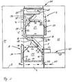
- Fig. 1 a two-tier arrangement for whole-body tanning is shown in a schematic vertical section.
- a lower whole-body tanning device 1 and an upper whole-body tanning device 2 are arranged one above the other in a common cabinet-like housing 3.
- the lower full-body tanning device 1 has a horizontal bed element 11, which is trough-shaped, corresponding to the body contour, and is fastened on a base 4 on the base of the common housing.
- a lower, vertical wall element 12 and an upper, obliquely arranged wall element 13 are attached to a longitudinal housing wall 5, adjacent to the bed element 11.
- the lower wall element 12 is fixedly arranged, while the upper wall element 13 can be attached to the housing wall 5 or to the lower wall element 12 so as to be inclinable.
- the upper wall element 13 extends close to a ceiling element 14 which, in the operating position, runs horizontally and parallel to the bed element 11.
- a lower and an upper entry element 15, 16 are provided in mirror image of the wall elements 12, 13, which can close an entry opening 10 in the lower region of a housing wall 7 and which, like the other elements 11 to 14 of the lower one Whole-body tanning device 1 are provided with UV lamps 40.
- Tubes extending in the longitudinal direction are used as UV lamps 40, which are arranged at a regular distance next to one another in the individual elements 11 to 16 of the whole-body tanning device 1. Due to the arrangement of these elements 11 to 16 in an operating position, an opaque tanning chamber 17 is formed, which ensures uniform all-over tanning on all sides.
- a hood-like arrangement of a height-adjustable ceiling element 14 and an inclinable, inclined Upper entry and wall element 16, 13 is particularly advantageously suitable for realizing individual tanning requests.
- Entry into the lower tanning chamber 17 takes place after the entry elements 15, 16 have been adjusted to an open position in which the entry opening 10 is released.
- the entry elements 15, 16 are moved on the outside of the housing wall 7 in rail-like guides (not shown) after the upper entry element 16, which is articulated on the lower entry element 15, has been pivoted into a vertical position (see double arrow X).
- this vertical position of the entry elements 15, 16, which can optionally be secured by locking or locking elements, is shown with solid lines.
- the operating position of the upper entry element 16 is indicated by dashed lines and the open position in the upper region of the housing wall 7 is indicated by dash-dotted contours.
- a vertical adjustment of the entry elements 15, 16 is particularly advantageous if these entry elements 15, 16 are formed in one piece in the longitudinal direction analogously to the other elements 11 to 14 of the lower whole-body tanning device 1.
- entry elements 15, 16 are arranged in the form of segments which can be pivoted to one another, a horizontal adjustment into a foot region in the manner of a folding door could take place. It would also be possible to pivot the segments into an adjacent changing room 31.
- the cover element 14 is also out of its horizontal operating position (dashed lines) can be swiveled into an open position (solid lines).
- the ceiling element 11 is securely held in the open position in a recess 18 which is formed on an intermediate floor 6 of the common housing 3 and can optionally have holding elements.
- the intermediate floor 6 runs almost horizontally over the entire length between the mutually parallel housing walls 5, 7 of the common housing 3 and separates the first lower whole-body tanning device 1 from the second, upper whole-body tanning device 2.
- This upper whole-body tanning device 2 is basically like the lower whole-body tanning device 1 is formed and thus also has a bed element 21, two wall elements 22, 23, an upper, pivotable ceiling element 24 and two entry elements 25, 26, which are provided with UV lamps and enclose a second tanning chamber 27.
- the vertical or obliquely arranged wall and entry elements 22, 23 and 25, 26, however, are arranged reversed in relation to the lower whole-body tanning device 1, so that the entry openings 10, 20 of the superposed whole-body tanning devices 1, 2 are arranged on opposite wall areas of the housing walls 5, 7, namely in the concave S-bend of the common housing 3 which is S-shaped in vertical section.
- the entry elements 25, 26 of the upper whole-body tanning device 2 are adjusted similarly to the lower whole-body tanning device 1 by pivoting the upper entry element 26 from an oblique operating position (dashed lines) into a vertical position (solid lines) and on the lower entry element 25 is secured in this position.
- the entry elements 25, 26 can then be accommodated in a receiving space 29, which is formed horizontally in an upper housing cover 8 of the common housing 3.
- the adjustment of the entry elements 15, 16 or 25, 26, an optionally formed height adjustment of the ceiling elements 14 or. 24 and the use of facial tanners arranged in the ceiling elements can advantageously be carried out by remote control.
- the housing walls 5, 7 are provided in the region of the wall elements 12, 13 and 22, 23 with a large-area and opaque cladding (not shown).
- cladding areas limited to the edge areas, for example the foot area, are attached. In this way, an insight into the tanning chambers 17, 27 is only possible from an associated, adjacent changing room 31, 32, and also only in the open position of the respective entry elements 15, 16 or 25, 26.
- cooling air is transported and possibly circulated along a common cooling air shaft, which is indicated schematically by arrows 50 and runs along the S-shaped vertical section of the common housing 3.
- the cooling air is sucked in through a suction opening 53 in the base 4 in the common housing 3 by a blower (not shown) and transported to the corresponding radiators 40 of the whole-body tanning devices 1, 2. It makes sense to cool the intake air in an air conditioning unit (not shown), which can be arranged in a platform 61.
- the platform 61 which acts as an access device 60 for overcoming the height difference between a floor 9 at normal height, as is present in the changing room 31 of the lower whole-body tanning device 1, and the upper whole-body tanning device 2 enables access to the tanning chamber 27.
- An exhaust air extraction 54 is provided in the area of the housing cover 8.
- the direction of flow of the cooling air can also be in the opposite direction.
- FIG. 2 shows a prefabricated container-like unit 30 with a double-tier arrangement according to FIG. 1 in a highly schematic plan view. Identical features are provided with identical reference symbols.
- the container-like unit 30 comprises in the illustrated embodiment a rear wall 33, two side walls 34, 35, front wall segments 36, 37 and 38, between which a lockable door 41 for the changing room 31 of the lower whole-body tanning device 1 and a lockable door 42 for the changing room 32 of the upper whole-body tanning device 2 are arranged.
- the doors 41, 42 are designed as swing doors.
- space-saving folding doors or doors designed as roller shutters are preferred.
- the changing room 31 of the lower full-body tanning device 1 is provided with a floor 9 at normal height and has an exhaust air duct 52 in the rear wall area, which can be connected to the exhaust air suction 54 of the common housing 3.
- the exhaust air duct 52 is expediently clad by a cloakroom 46.
- a mirror 43 is arranged on the side wall 34.
- the changing room 32 is assigned to the whole-body tanning device 2.
- This changing room 32 is basically the same size as the changing room 31, but has that in Connection to the platform 61 described in FIG. 1 and a staircase 62 between the access door 42 and the platform 61 as an access device 60.
- the stairs 62 are provided with a railing or with a handrail 63.
- a cloakroom 45 is arranged in the rear part of the changing room 32.
- a narrow, elevated aisle 64 is left between the platform 61 and the common housing 3 in order to facilitate access to the tanning chamber 27 and to keep the cloakroom 45 accessible.
- a mirror 44 is attached to the side wall 35 in the region of the platform 61.
- the container-like unit 30 with a two-tier arrangement of two whole-body tanning devices 1, 2 not only allows pre-assembly of the whole-body tanning devices 1, 2 by the manufacturer in the common housing 3, but also the respective changing rooms 31, 32. Only the installation then has to be carried out on site electrical connections.
- FIG. 3 shows, as a second exemplary embodiment of the arrangement for whole-body tanning according to the invention, a diagram of a three-tier arrangement with a first whole-body tanning device 57 accessible at floor level 9, a second whole-body tanning device 56 arranged underneath and a third one arranged above the first whole-body tanning device 57 Whole body tanning device 58 shown.
- the three goose-body tanning devices 56, 57, 58 are arranged in a common housing 55 that is meandering in the vertical direction and are each accessible via separate access openings (not shown).
- escalators are also suitable as access devices (not shown) for the upper whole-body tanning device 58 and the lower whole-body tanning device 56.
- the side Arrows shown indicate the adjustment movements of the entry elements, not shown, of the three full-body tanning devices 56, 57, 58.
- Fig. 4 illustrates a possible arrangement of more than three whole-body tanning devices 59 ... n one above the other. Access to these whole-body tanning devices is made possible by a movement of the devices themselves (not shown). For example, it is possible to use each individual full-body tanning device 59 ... n as needed from a changing room that has several changing rooms for individual users.
- FIG. 5 shows three whole-body tanning devices 80, 81, 82 arranged one above the other, which are connected to a device unit 70 and are moved in the manner of an elevator (arrow 71) for getting in and out.
- the arrangement allows entry and exit on one or both sides at the level of a floor 9.
- the jointly moving whole-body tanning devices 80, 81, 82 are controlled with the aid of a program by entering the respective tanning time.
- FIG. 6 shows a device unit 70 with 8 whole-body tanning devices 83 to 90, which are subjected to a paternoster-like movement and are pivotably arranged on a movement device, which is shown with dashed lines.
- the whole-body tanning devices 83 to 90 are arranged one above the other and next to one another, as well as offset, and are provided with separately accessible entry openings (not shown).
- FIG. 7 shows a two-tier arrangement of two whole-body tanning devices 91, 92 which can be moved in a circle on a lever 94.
- the lever 94 has an axis of rotation 95 on, which is arranged in the middle between the axes of rotation 96, 97 of the whole-body tanning devices 91, 92.
- the device unit 70 is arranged so that the upper whole-body tanning device is accessible from a floor 9.
- the common housing (not shown) can consist of a carrier arrangement with a paneling which only delimits the entry area.
Landscapes
- Health & Medical Sciences (AREA)
- Engineering & Computer Science (AREA)
- Biomedical Technology (AREA)
- Pathology (AREA)
- Nuclear Medicine, Radiotherapy & Molecular Imaging (AREA)
- Radiology & Medical Imaging (AREA)
- Life Sciences & Earth Sciences (AREA)
- Animal Behavior & Ethology (AREA)
- General Health & Medical Sciences (AREA)
- Public Health (AREA)
- Veterinary Medicine (AREA)
- Accommodation For Nursing Or Treatment Tables (AREA)
- Superheterodyne Receivers (AREA)
- Finger-Pressure Massage (AREA)
- Treatment And Processing Of Natural Fur Or Leather (AREA)
Applications Claiming Priority (2)
| Application Number | Priority Date | Filing Date | Title |
|---|---|---|---|
| DE4224517A DE4224517C2 (de) | 1992-07-24 | 1992-07-24 | Anordnung zur Ganzkörper-Bräunung |
| DE4224517 | 1992-07-24 |
Publications (3)
| Publication Number | Publication Date |
|---|---|
| EP0580175A2 true EP0580175A2 (fr) | 1994-01-26 |
| EP0580175A3 EP0580175A3 (en) | 1997-06-25 |
| EP0580175B1 EP0580175B1 (fr) | 2000-05-10 |
Family
ID=6464033
Family Applications (1)
| Application Number | Title | Priority Date | Filing Date |
|---|---|---|---|
| EP93111882A Expired - Lifetime EP0580175B1 (fr) | 1992-07-24 | 1993-07-23 | Disposition pour le bronzage du corps entier |
Country Status (3)
| Country | Link |
|---|---|
| EP (1) | EP0580175B1 (fr) |
| AT (1) | ATE192665T1 (fr) |
| DE (1) | DE4224517C2 (fr) |
Families Citing this family (2)
| Publication number | Priority date | Publication date | Assignee | Title |
|---|---|---|---|---|
| DE19617410C2 (de) * | 1996-04-30 | 2002-01-24 | Kratz Josef Gmbh | Verfahren und Anordnung zur Klimatisierung einer Bräunungskabine |
| DE19640118A1 (de) * | 1996-09-28 | 1998-04-02 | Uwe Unterwasser Electric Gmbh | Bestrahlungsgerät, insbesondere Solarium |
Family Cites Families (8)
| Publication number | Priority date | Publication date | Assignee | Title |
|---|---|---|---|---|
| DE2313103A1 (de) * | 1973-03-16 | 1974-09-19 | Silgmann Kg Saunabau | Saunakabine |
| DE7702715U1 (de) * | 1977-01-31 | 1977-07-14 | Neumann, Gert H., Dipl.-Kfm., 6085 Nauheim | Raumkoerper mit sauna und solarium |
| DE2717723A1 (de) * | 1977-04-21 | 1978-10-26 | Lorenz Kesting | Als doppelstockgarage dienendes gebaeude aus fertigteilen |
| DE8429036U1 (de) * | 1984-10-03 | 1985-08-01 | artec design GmbH, 5630 Remscheid | Bräunungsgerät |
| FR2585957A1 (fr) * | 1985-03-29 | 1987-02-13 | Nizard Charles | Systeme de bronzage integral a mouvement horizontal controle |
| DE3603055A1 (de) * | 1986-01-30 | 1987-08-06 | Juergen Kutzner | Schlafkabinensystem |
| DE8616689U1 (de) * | 1986-06-23 | 1986-11-06 | Pürschel, Dieter, 4600 Dortmund | Ganzkörperbestrahlungsgerät |
| DE3708872A1 (de) * | 1987-03-18 | 1988-09-29 | Kratz Josef Gmbh | Ganzkoerper-braeunungsgeraet |
-
1992
- 1992-07-24 DE DE4224517A patent/DE4224517C2/de not_active Expired - Fee Related
-
1993
- 1993-07-23 EP EP93111882A patent/EP0580175B1/fr not_active Expired - Lifetime
- 1993-07-23 AT AT93111882T patent/ATE192665T1/de not_active IP Right Cessation
Also Published As
| Publication number | Publication date |
|---|---|
| DE4224517C2 (de) | 1995-05-24 |
| EP0580175B1 (fr) | 2000-05-10 |
| ATE192665T1 (de) | 2000-05-15 |
| EP0580175A3 (en) | 1997-06-25 |
| DE4224517A1 (de) | 1994-02-03 |
Similar Documents
| Publication | Publication Date | Title |
|---|---|---|
| DE69314023T2 (de) | Bürotischsystem | |
| EP1918650B1 (fr) | Procédé de climatisation d'une pièce et dispositif de climatisation | |
| DE10010119A1 (de) | Verfahren und Vorrichtung zur Belüftung und Temperierung eines Raumes | |
| EP0287106B1 (fr) | Chauffage pour un sauna | |
| EP0580175A2 (fr) | Disposition pour le bronzage du corps entier | |
| DE4119364C2 (de) | Arbeitstisch mit eingebauten elektrischen Geräten | |
| DE3231317A1 (de) | Geraet zur uv-nahbestrahlung, insbesondere bestrahlungsliege | |
| DE3727882C2 (de) | Verfahren zur Klimatisierung von Räumen sowie Klimatisierungssystem zur Durchführung des Verfahrens | |
| EP0298952B1 (fr) | Cabine de conduite de véhicule ferroviaire | |
| EP2161512B1 (fr) | Appareil d'aération décentralisé et installation d'aération dotée d'un tel appareil | |
| DE3123378A1 (de) | Bestrahlungsgeraet | |
| WO2011107261A1 (fr) | Dispositif pour éclairer des pièces | |
| DE4416997A1 (de) | Klappbare Saunakabine | |
| DE2163690C2 (de) | Sauna-Entlüftungsvorrichtung | |
| DE9106753U1 (de) | Vorrichtung zur Klimatisierung von Räumen | |
| DE9218498U1 (de) | Vorrichtung zum Bräunen des menschlichen Körpers | |
| DE19617410C2 (de) | Verfahren und Anordnung zur Klimatisierung einer Bräunungskabine | |
| DE3931574A1 (de) | Gestell fuer bildschirmgeraete | |
| DE19739863C2 (de) | Dunstabzugshaube | |
| EP0601331B1 (fr) | Appareil de bronzage du corps entier | |
| DE2833558C2 (de) | Vorrichtung zur Umlenkung der Warmluft bei einem Heizkörper | |
| DE19632105B4 (de) | Badekabine zum Saunen und Kuren | |
| DE2110781A1 (de) | Vorrichtung zum Heizen oder Kuehlen von Raeumen | |
| EP0305335A2 (fr) | Chambre de sortie pour la distribution d'air dans une pièce à ventiler | |
| DE9405934U1 (de) | Umluftkühlung mit Kühlung für eine Bestrahlungsliege |
Legal Events
| Date | Code | Title | Description |
|---|---|---|---|
| PUAI | Public reference made under article 153(3) epc to a published international application that has entered the european phase |
Free format text: ORIGINAL CODE: 0009012 |
|
| AK | Designated contracting states |
Kind code of ref document: A2 Designated state(s): AT BE CH DE DK ES FR GB IT LI LU NL SE |
|
| PUAL | Search report despatched |
Free format text: ORIGINAL CODE: 0009013 |
|
| AK | Designated contracting states |
Kind code of ref document: A3 Designated state(s): AT BE CH DE DK ES FR GB IT LI LU NL SE |
|
| 17P | Request for examination filed |
Effective date: 19970702 |
|
| 17Q | First examination report despatched |
Effective date: 19980508 |
|
| GRAG | Despatch of communication of intention to grant |
Free format text: ORIGINAL CODE: EPIDOS AGRA |
|
| GRAG | Despatch of communication of intention to grant |
Free format text: ORIGINAL CODE: EPIDOS AGRA |
|
| GRAG | Despatch of communication of intention to grant |
Free format text: ORIGINAL CODE: EPIDOS AGRA |
|
| GRAH | Despatch of communication of intention to grant a patent |
Free format text: ORIGINAL CODE: EPIDOS IGRA |
|
| GRAH | Despatch of communication of intention to grant a patent |
Free format text: ORIGINAL CODE: EPIDOS IGRA |
|
| GRAA | (expected) grant |
Free format text: ORIGINAL CODE: 0009210 |
|
| RBV | Designated contracting states (corrected) |
Designated state(s): AT BE CH DK ES FR GB IT LI LU NL SE |
|
| AK | Designated contracting states |
Kind code of ref document: B1 Designated state(s): AT BE CH DK ES FR GB IT LI LU NL SE |
|
| PG25 | Lapsed in a contracting state [announced via postgrant information from national office to epo] |
Ref country code: NL Free format text: LAPSE BECAUSE OF FAILURE TO SUBMIT A TRANSLATION OF THE DESCRIPTION OR TO PAY THE FEE WITHIN THE PRESCRIBED TIME-LIMIT Effective date: 20000510 Ref country code: IT Free format text: LAPSE BECAUSE OF FAILURE TO SUBMIT A TRANSLATION OF THE DESCRIPTION OR TO PAY THE FEE WITHIN THE PRESCRIBED TIME-LIMIT;WARNING: LAPSES OF ITALIAN PATENTS WITH EFFECTIVE DATE BEFORE 2007 MAY HAVE OCCURRED AT ANY TIME BEFORE 2007. THE CORRECT EFFECTIVE DATE MAY BE DIFFERENT FROM THE ONE RECORDED. Effective date: 20000510 Ref country code: GB Free format text: LAPSE BECAUSE OF FAILURE TO SUBMIT A TRANSLATION OF THE DESCRIPTION OR TO PAY THE FEE WITHIN THE PRESCRIBED TIME-LIMIT Effective date: 20000510 Ref country code: FR Free format text: LAPSE BECAUSE OF FAILURE TO SUBMIT A TRANSLATION OF THE DESCRIPTION OR TO PAY THE FEE WITHIN THE PRESCRIBED TIME-LIMIT Effective date: 20000510 Ref country code: ES Free format text: THE PATENT HAS BEEN ANNULLED BY A DECISION OF A NATIONAL AUTHORITY Effective date: 20000510 |
|
| REF | Corresponds to: |
Ref document number: 192665 Country of ref document: AT Date of ref document: 20000515 Kind code of ref document: T |
|
| REG | Reference to a national code |
Ref country code: CH Ref legal event code: NV Representative=s name: BUECHEL & PARTNER AG PATENTBUERO Ref country code: CH Ref legal event code: EP |
|
| REG | Reference to a national code |
Ref country code: DE Ref legal event code: 8566 |
|
| PG25 | Lapsed in a contracting state [announced via postgrant information from national office to epo] |
Ref country code: LU Free format text: LAPSE BECAUSE OF NON-PAYMENT OF DUE FEES Effective date: 20000723 |
|
| PGFP | Annual fee paid to national office [announced via postgrant information from national office to epo] |
Ref country code: AT Payment date: 20000726 Year of fee payment: 8 |
|
| PG25 | Lapsed in a contracting state [announced via postgrant information from national office to epo] |
Ref country code: BE Free format text: LAPSE BECAUSE OF NON-PAYMENT OF DUE FEES Effective date: 20000731 |
|
| PG25 | Lapsed in a contracting state [announced via postgrant information from national office to epo] |
Ref country code: SE Free format text: LAPSE BECAUSE OF FAILURE TO SUBMIT A TRANSLATION OF THE DESCRIPTION OR TO PAY THE FEE WITHIN THE PRESCRIBED TIME-LIMIT Effective date: 20000810 Ref country code: DK Free format text: LAPSE BECAUSE OF FAILURE TO SUBMIT A TRANSLATION OF THE DESCRIPTION OR TO PAY THE FEE WITHIN THE PRESCRIBED TIME-LIMIT Effective date: 20000810 |
|
| NLV1 | Nl: lapsed or annulled due to failure to fulfill the requirements of art. 29p and 29m of the patents act | ||
| EN | Fr: translation not filed | ||
| GBV | Gb: ep patent (uk) treated as always having been void in accordance with gb section 77(7)/1977 [no translation filed] |
Effective date: 20000510 |
|
| BERE | Be: lapsed |
Owner name: JOSEF KRATZ G.M.B.H. JK Effective date: 20000731 |
|
| PLBE | No opposition filed within time limit |
Free format text: ORIGINAL CODE: 0009261 |
|
| STAA | Information on the status of an ep patent application or granted ep patent |
Free format text: STATUS: NO OPPOSITION FILED WITHIN TIME LIMIT |
|
| 26N | No opposition filed | ||
| PG25 | Lapsed in a contracting state [announced via postgrant information from national office to epo] |
Ref country code: AT Free format text: LAPSE BECAUSE OF NON-PAYMENT OF DUE FEES Effective date: 20010723 |
|
| PGFP | Annual fee paid to national office [announced via postgrant information from national office to epo] |
Ref country code: CH Payment date: 20020731 Year of fee payment: 10 |
|
| REG | Reference to a national code |
Ref country code: CH Ref legal event code: PFA Free format text: JK-JOSEF KRATZ GMBH TRANSFER- JK-HOLDING GMBH |
|
| PG25 | Lapsed in a contracting state [announced via postgrant information from national office to epo] |
Ref country code: LI Free format text: LAPSE BECAUSE OF NON-PAYMENT OF DUE FEES Effective date: 20030731 Ref country code: CH Free format text: LAPSE BECAUSE OF NON-PAYMENT OF DUE FEES Effective date: 20030731 |
|
| REG | Reference to a national code |
Ref country code: CH Ref legal event code: PL |