EP0580175B1 - Disposition pour le bronzage du corps entier - Google Patents
Disposition pour le bronzage du corps entier Download PDFInfo
- Publication number
- EP0580175B1 EP0580175B1 EP93111882A EP93111882A EP0580175B1 EP 0580175 B1 EP0580175 B1 EP 0580175B1 EP 93111882 A EP93111882 A EP 93111882A EP 93111882 A EP93111882 A EP 93111882A EP 0580175 B1 EP0580175 B1 EP 0580175B1
- Authority
- EP
- European Patent Office
- Prior art keywords
- whole body
- body tanning
- arrangement according
- housing
- devices
- Prior art date
- Legal status (The legal status is an assumption and is not a legal conclusion. Google has not performed a legal analysis and makes no representation as to the accuracy of the status listed.)
- Expired - Lifetime
Links
- 238000001816 cooling Methods 0.000 claims description 12
- 238000004378 air conditioning Methods 0.000 claims description 3
- 238000010276 construction Methods 0.000 claims description 3
- 238000005096 rolling process Methods 0.000 claims 1
- 238000005253 cladding Methods 0.000 description 3
- 238000000605 extraction Methods 0.000 description 3
- 238000009434 installation Methods 0.000 description 3
- 238000004519 manufacturing process Methods 0.000 description 3
- 230000015572 biosynthetic process Effects 0.000 description 2
- 238000011161 development Methods 0.000 description 2
- 230000018109 developmental process Effects 0.000 description 2
- 230000001815 facial effect Effects 0.000 description 2
- 238000005755 formation reaction Methods 0.000 description 2
- 230000005855 radiation Effects 0.000 description 2
- 241000272814 Anser sp. Species 0.000 description 1
- 230000009286 beneficial effect Effects 0.000 description 1
- NJPPVKZQTLUDBO-UHFFFAOYSA-N novaluron Chemical compound C1=C(Cl)C(OC(F)(F)C(OC(F)(F)F)F)=CC=C1NC(=O)NC(=O)C1=C(F)C=CC=C1F NJPPVKZQTLUDBO-UHFFFAOYSA-N 0.000 description 1
- 238000004091 panning Methods 0.000 description 1
- 239000000725 suspension Substances 0.000 description 1
- 238000009423 ventilation Methods 0.000 description 1
Images


Classifications
-
- A—HUMAN NECESSITIES
- A61—MEDICAL OR VETERINARY SCIENCE; HYGIENE
- A61N—ELECTROTHERAPY; MAGNETOTHERAPY; RADIATION THERAPY; ULTRASOUND THERAPY
- A61N5/00—Radiation therapy
- A61N5/06—Radiation therapy using light
- A61N5/0613—Apparatus adapted for a specific treatment
- A61N5/0614—Tanning
-
- A—HUMAN NECESSITIES
- A61—MEDICAL OR VETERINARY SCIENCE; HYGIENE
- A61N—ELECTROTHERAPY; MAGNETOTHERAPY; RADIATION THERAPY; ULTRASOUND THERAPY
- A61N5/00—Radiation therapy
- A61N5/06—Radiation therapy using light
- A61N2005/0635—Radiation therapy using light characterised by the body area to be irradiated
- A61N2005/0636—Irradiating the whole body
-
- A—HUMAN NECESSITIES
- A61—MEDICAL OR VETERINARY SCIENCE; HYGIENE
- A61N—ELECTROTHERAPY; MAGNETOTHERAPY; RADIATION THERAPY; ULTRASOUND THERAPY
- A61N5/00—Radiation therapy
- A61N5/06—Radiation therapy using light
- A61N2005/065—Light sources therefor
- A61N2005/0655—Tubes
Definitions
- the invention relates to an arrangement for whole-body tanning.
- Tanning devices based on UV lamps are available in a wide variety Formations and sizes known. More special Tanning devices for whole-body tanning are popular. These have a bank as the lower part, which is like a top that is spaced from the bench on a tripod or can also be attached to a ceiling suspension, is equipped with UV lamps. Usually the top is height adjustable, so that individual tanning wishes can be fulfilled. A pivotable around the longitudinal axis The arrangement of the upper part enables easy entry in a tanning device.
- tanning salons are known, in which in particular Whole body tanning equipment for commercial use be fed. Due to a great demand these tanning or tanning salons increasingly in medium to very good neighborhoods and housing estates, in which rental prices above the average are common are.
- From the post-published DE 42 28 820 A1 is a device with an air-conditioned whole-body radiation device known, which is in a closed, walkable Cabin arranged with an adjustable air conditioning unit is.
- the radiation device has a couch and a lid, which is provided with UV lamps.
- For the air supply and exhaust are a long side and entire ceiling of the cabin designed as air guiding chambers.
- the invention has for its object to enable a particularly good profitability of a tanning salon.
- a basic idea of the invention is to be effective Land use by including the available standing room height for an arrangement of whole-body tanning devices to achieve.
- a first full-body tanning device should be from a normal height floor be accessible through a manhole.
- the access device serves overcoming the height difference between the floor and any other full-body tanning device and can in a particularly simple version a staircase or to be a pedestal.
- each whole-body tanning device has a separate entrance opening, which can be opened by at least an entry element can be closed and advantageously with regard to the associated one Cloakroom or changing rooms expediently in devices arranged one above the other arranged on opposite side walls are.
- full-body tanning devices Thanks to the multi-level arrangement of full-body tanning devices is a high use of space in tanning salons reached. For example, for a double-decker arrangement only half the area compared to the usual Installation of two full-body tanning devices required, resulting in a significant reduction in rental costs per full-body tanning device results.
- studio space is also saved because because the changing rooms are opposite each other Entry openings directly adjacent to these can be arranged.
- this can common housing which is cabinet-like or frame-like can be trained up to the area of the studio ceiling pass.
- an opaque covering of the common Housing is a full body tanning device each made up of several elements, which in Operating position an almost closed tanning chamber enclose.
- the individual elements comprise one in a constructive way preferred training a couch element, a parallel arranged ceiling element and laterally arranged wall and Entry elements, which in the longitudinal direction with UV lamps are provided and in the operating position an all-round Allow full body tanning.
- the head area of the ceiling element and if necessary an adjacent one Wall element and an entry element with integrated Facial tanning is provided.
- the wall element and the entry element are particularly oblique and mirror images arranged to each other.
- At least one entry element expediently an entry element vertically adjoining the bed element, and a second, upper entry element are individual or jointly adjustable and can be made from an operating position in which it is a mirror image of one or two arranged wall elements are held in be moved to an open position in which a convenient entry into the tanning chamber.
- the entry elements in the vertical direction on Housing for example in corresponding guide rails, be moved until the manhole is released is.
- An adjustment of the entry elements expediently takes place after the upper Entry element, that on the lower, vertical entry element is articulated and in the operating position at an angle between the lower entry element and the ceiling element runs, in a vertical, with the lower entry element aligned position was pivoted.
- the ceiling element which is preferably made in one piece and is arranged horizontally in the operating position, adjustable to fix. If in the adjacent area of the common housing is formed a recess the ceiling element, for example, in a swung open or even shifted position particularly easily and safely held during boarding.
- a preferred arrangement according to the invention which is characterized by a clear construction of the housing and changing rooms distinguished, has two full-body tanning devices in a cabinet-like housing, double-decker and aligned with each other.
- the housing can be in this arrangement in the vertical section the shape of a stylized S have, in the concave S-bow sides each there is an entry opening of a whole-body tanning device.
- the recess for a swing-out ceiling element of the lower whole-body tanning device is in or on an intermediate floor of the common housing.
- the recess for the ceiling element of the upper full-body tanning device is located in or on the housing ceiling.
- the entry-level elements of the upper full-body tanning device can be used to release an entry area in a expedient and space-saving way in a recording room be moved in the area of the housing ceiling, while the entry elements of the lower full-body tanning device in an upper area of the outside of the Housing wall are slidable.
- a two-story and increasingly a multi-story Arrangement of two or more full-body tanning devices can, in addition to efficient use of space also energetic advantages because a common cooling system, for example a common cooling air shaft, and a common exhaust ventilation can be installed.
- an appropriately trained access device the inventive arrangement to an effective Contribute land use. If, for example, as an access device to the upper whole-body tanning device Double-decker arrangement a platform accessible by stairs is provided, the space below the platform to accommodate one air conditioner but also others Devices used to operate the whole body tanning equipment become.
- individual whole-body tanning devices or a device unit adjustable from several full-body tanning devices for example in the vertical or horizontal direction can be moved or moved on an inclined plane.
- a single full-body tanning device to get in or out of a common Changing room with single cabins or to individually assigned Moving changing rooms or changing rooms.
- full body tanning equipment When stacked and next to each other on a common conveyor attached full body tanning equipment can be a paternoster-like orbital movement to overcome the height difference between at least one floor and the respective one Whole body tanning device.
- Control of the orbital movement makes sense.
- In dependence of the number of whole-body tanning devices in one Unit can be on both outer sides of the unit Changing rooms or changing rooms can be arranged.
- a circularly movable is also advantageous
- Two-tier arrangement of at least two full-body tanning devices which is a divided changing room or else a locker room with cabins assigned to an entry side could be.
- the end faces of two full-body tanning devices are at one end of a rotatably mounted two-armed lever, wherein the axis of rotation for the lever between each Whole body tanning equipment and approximately in the middle of the lever is arranged.
- FIG. 1 is a schematic vertical section Two-tier arrangement for full-body tanning is shown.
- a lower whole-body tanning device 1 and an upper one Whole body tanning device 2 are in a common cabinet-like housing 3 arranged one above the other.
- the lower Whole body tanning device 1 has a horizontal Lying element 11, which is trough-shaped, the body contour trained accordingly and on a bottom side Socket 4 of the common housing is attached.
- a lower, vertical wall element 12 and an upper, obliquely arranged wall element 13 attached.
- the lower wall element 12 is fixed, while the upper wall element 13 tilt adjustable on the housing wall 5 or can be attached to the lower wall element 12.
- the upper wall element 13 extends close to a ceiling element 14, which in the operating position is horizontal and runs parallel to the bed element 11.
- a lower mirror image of the wall elements 12, 13 and an upper entry element 15, 16 is provided, which a Entry opening 10 in the lower region of a housing wall 7 can close and which like the other elements 11 to 14 of the lower whole-body tanning device 1 with UV lamps 40 are provided.
- the UV emitters 40 are longitudinal ones Tubes used that are next to each other at regular intervals in the individual elements 11 to 16 of the Whole body tanning device 1 are arranged. Due to the Arrangement of these elements 11 to 16 in an operating position is an opaque tanning chamber 17 formed, the all-round uniform whole-body tanning guaranteed.
- a hood-like arrangement of a height-adjustable Ceiling element 14 and an inclinable, inclined upper entry and wall element 16, 13 is special advantageously suitable to realize individual tanning requests.
- An entry into the lower tanning chamber 17 takes place after an adjustment of the entry elements 15, 16 in a Open position in which the entry opening 10 is released is.
- the entry elements 15, 16 on the outside of the housing wall 7 moved in rail-like guides (not shown), after the upper entry element 16, which at the lower Entry element 15 is articulated in a vertical position was pivoted (see double arrow X). 1 is this vertical position of the entry elements 15, 16, if necessary secured by locking or locking elements can be represented by solid lines.
- the operating position of the upper entry element 16 is with dashed lines Lines and the opening position in the upper area the housing wall 7 is with dash-dotted contours identified.
- a vertical adjustment of the entry elements 15, 16 is particularly advantageous if these entry elements 15, 16 analogous to the other elements 11 to 14 of the lower one Whole body tanning device 1 in one piece in the longitudinal direction are trained.
- entry elements 15, 16 in the form of giftable to each other articulated segments could be arranged horizontal adjustment in a foot area like a Folding door. Panning would also be possible of the segments in an adjacent changing room 31.
- the ceiling element 14 For an unhindered, comfortable entry into the whole body tanning device To enable 1 is also the ceiling element 14 from its horizontal operating position (dashed lines) in an open position (solid Lines) swiveling. A secure mounting of the ceiling element 14 in the open position takes place in one Recess 18 on an intermediate floor 6 of the common Housing 3 is formed and optionally holding elements can have.
- the intermediate floor 6 runs almost horizontally over the entire Length between the parallel housing walls 5, 7 of the common housing 3 and separates the first lower whole-body tanning device 1 from the second, upper Whole body tanning device 2.
- This upper full body tanning device 2 is basically like the lower whole-body tanning device 1 trained and thus also has Couch element 21, two wall elements 22, 23, an upper one, swing-open ceiling element 24 and two entry elements 25, 26, which are provided with UV lamps and one enclose the second browning chamber 27.
- the vertical or diagonally arranged wall and entry elements 22, 23 or 25, 26 however compared to the lower whole-body tanning device 1 arranged upside down, so that the manholes 10, 20 of the one above the other Whole-body tanning devices 1, 2 on opposite one another Wall areas of the housing walls 5, 7, namely in the concave S-bow of the common S-shaped in vertical section Housing 3 are arranged.
- An adjustment of the entry elements 25, 26 of the upper whole-body tanning device 2 is similar to the lower full-body tanning device 1 by the upper entry element 26 an oblique operating position (dashed lines) in a vertical position (solid lines) panned and secured in this position on the lower entry element 25 becomes.
- the entrance elements can be similar to a blind 25, 26 can then be accommodated in a receiving space 29, the horizontal in an upper housing cover 8 of the common Housing 3 is formed.
- the adjustment of the Entry elements 15, 16 and 25, 26, one if necessary trained height adjustment of the ceiling elements 14 bw. 24th and the use of arranged in the ceiling elements Facial tanners can advantageously be operated by remote control respectively.
- the housing walls 5, 7 are in the area of the wall elements 12, 13 or 22, 23 with a large and opaque Provide cladding (not shown).
- 20 are on the edge areas, for example the foot area, limited cladding areas appropriate. This is an insight into the tanning chambers 17, 27 only from an associated, adjacent Changing room 31, 32 possible and only in the open position the respective entry elements 15, 16 and 25, 26.
- the UV lamp 40 in addition to that required for tanning electromagnetic energy also generate thermal energy cooling of the emitters or the tanning chambers 17, 27 intended.
- a common cooling air duct which through Arrows 50 is indicated schematically and along the S-shaped vertical section of the common housing 3 runs, cool air is transported and, if necessary, circulated.
- the cooling air is in via an intake opening 53 bottom base 4 in the common housing 3 through a blower, not shown, is sucked in and fed to the corresponding Spotlights 40 of the whole-body tanning devices 1, 2 transported. It makes sense to cool the intake Air in an air conditioning unit (not shown), which in a platform 61 can be arranged.
- the platform 61 which serves as an access device 60 for overcoming the height difference between a floor 9 in Normal height as in the locker room 31 of the lower one Whole body tanning device 1 is present, and the upper Whole body tanning device 2 gives access to Tanning chamber 27.
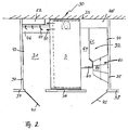
- FIG. 2 is a prefabricated container-like unit 30 with a two-story arrangement according to FIG. 1 in one shown highly schematic top view. Same features are provided with identical reference symbols.
- the container-like unit 30 comprises in the illustrated Embodiment a rear wall 33, two side walls 34, 35, front wall segments 36, 37 and 38, between which one lockable door 41 for the locker room 31 of the lower one Whole body tanning device 1 and a lockable door 42 for the locker room 32 of the upper full-body tanning device 2 are arranged.
- the Doors 41, 42 designed as swing doors. Are preferred however, space-saving folding doors or roller shutters Doors.
- the changing room 31 of the lower full-body tanning device 1 is with a floor 9 at normal height provided and has a in the rear area Exhaust air duct 52, which is connected to the exhaust air suction 54 of the common housing 3 can be connected.
- the exhaust air duct 52 is expediently clad by a cloakroom 46.
- a mirror 43 is arranged on the side wall 34.
- the changing room 32 is the whole-body tanning device 2 assigned.
- This changing room 32 is basically the same the size of the dressing room 31, but shows that in Connection with the platform 61 described in FIG. 1 and a Stairs 62 between the access door 42 and the platform 61 as Access device 60 on.
- the stairs 62 are with a Railing or provided with a handrail 63.
- a cloakroom 45 arranged in the back Part of the changing room 32 .
- Between the platform 61 and the common one Housing 3 is a narrow, elevated aisle 64 left to to facilitate entry into the tanning chamber 27 and to keep the wardrobe 45 accessible.
- a region 44 of the platform 61 on the side wall 35 is a mirror 44 appropriate.
- Fig. 3 is as a second embodiment arrangement according to the invention for whole-body tanning Scheme of a three-story arrangement with an in Floor height 9 accessible first full-body tanning device 57, a second full-body tanning device arranged underneath 56 and one over the first full-body tanning device 57 arranged third whole-body tanning device 58 reproduced.
- the three goose body tanning devices 56, 57, 58 are in a vertical cut meandering common housing 55 arranged and each via separate entry openings (not shown) accessible.
- access devices (not shown) for the upper whole-body tanning device 58 and the lower whole-body tanning device 56 are also suitable Stairs and pedestals also escalators.
- the side The arrows shown indicate the adjustment movements of the Entry elements, not shown, of the three full-body tanning devices 56, 57, 58.
- Fig. 4 illustrates a possible arrangement of more than three superimposed whole-body tanning devices 59 ... n Access to these full-body tanning devices is through a Movement of the devices themselves enables (not shown). So it is possible, for example, every single one Whole body tanning device 59 ... n as required by one Changing room that has multiple changing rooms for individual users has to use.
- FIG. 5 shows three whole-body tanning devices arranged one above the other 80, 81, 82, which are connected to a device unit 70 are elevator-like for getting in and out (arrow 71) can be moved.
- the arrangement allows one or also two-sided entry and exit at the level of a floor 9.
- the jointly moving whole-body tanning devices 80, 81, 82 are entered using a program controlled the respective tanning time.
- FIG. 6 shows a device unit 70 with 8 whole-body tanning devices 83 to 90, that of a paternoster-like movement be subjected to and pivoted on a movement device, which are shown with dashed lines is arranged.
- the whole body tanning devices 83 to 90 are arranged one above the other, next to one another and offset and with separately accessible entry openings (not shown).
- the device unit 70 is arranged so that the upper one Whole body tanning device accessible from a floor 9 is.
- the common housing (not shown) can consist of a carrier arrangement with only the entry area limiting cladding exist.
Landscapes
- Health & Medical Sciences (AREA)
- Engineering & Computer Science (AREA)
- Biomedical Technology (AREA)
- Pathology (AREA)
- Nuclear Medicine, Radiotherapy & Molecular Imaging (AREA)
- Radiology & Medical Imaging (AREA)
- Life Sciences & Earth Sciences (AREA)
- Animal Behavior & Ethology (AREA)
- General Health & Medical Sciences (AREA)
- Public Health (AREA)
- Veterinary Medicine (AREA)
- Accommodation For Nursing Or Treatment Tables (AREA)
- Superheterodyne Receivers (AREA)
- Finger-Pressure Massage (AREA)
- Treatment And Processing Of Natural Fur Or Leather (AREA)
Claims (27)
- Ensemble de bronzage intégral, caractérisé en ce quea) au moins deux appareils de bronzage intégral (1, 2, 56-59, 80-92) sont disposés sur plusieurs étages dans un logement commun (3, 55),b) en ce que chaque appareil de bronzage intégral (1, 2, 56-59, 80-92) présente plusieurs éléments (11-16 ; 21-26) munis de projecteurs à UV (40), éléments qui, dans leur position de service, entourent chacun une chambre de bronzage (17, 27),c) en ce que les appareils de bronzage intégral (1, 2, 56-59, 80-92) présentent des ouvertures d'entrée séparées (10, 20) qui peuvent être fermées par au moins un élément d'entrée (15, 16 ; 25, 26),d) en ce qu' un premier appareil de bronzage intégral (1) est accessible depuis un plancher (9), ete) en ce que pour surmonter une différence de hauteur entre le plancher (9) et chaque autre appareil de bronzage intégral (2, 56-59, 80-92), il est prévu un dispositif d'accès (60).
- Ensemble selon la Revendication 1, caractérisé en ce que les ouvertures d'entrée (10 ; 20) desdits au moins deux appareils de bronzage intégral (1, 2) sont prévues sur des parois latérales mutuellement opposées (7, 5) du logement (3, 55).
- Ensemble selon la Revendication 1 ou 2, caractérisé en ce que chaque appareil de bronzage intégral (1, 2, 56-59, 80-92) présente un élément formant couchette (11 ; 21) et au moins un élément formant paroi (12, 13 ; 22, 23), ainsi qu'un élément formant plafond (14 ; 24) placé parallèlement à l'élément formant couchette (11 ; 21), et en ce qu' au moins un élément d'entrée (15, 16 ; 25, 26) est placé entre l'élément formant couchette (11 ; 21) et l'élément formant plafond (14 ; 24).
- Ensemble selon l'une quelconque des Revendications 1 à 3, caractérisé en ce que sont prévus contigus à l'élément formant couchette (11 ; 21), un élément d'entrée inférieur vertical (15 ; 25) et un élément d'entrée supérieur (16 ; 26), éléments qui sont placés mobiles sur un logement commun (3, 55) entre une position de service et une position d'ouverture.
- Ensemble selon la Revendication 4, caractérisé en ce que l'élément d'entrée supérieur (16 ; 26), qui est monté pivotant sur l'élément d'entrée inférieur (15 ; 25), est tenu incliné dans la position de service entre l'élément d'entrée inférieur (15 ; 25) et l'élément formant plafond (14 ; 24), et en ce que , pour la position d'ouverture, l'élément d'entrée supérieur (16 ; 26) pivoté en position verticale est mobile, conjointement avec l'élément d'entrée inférieur (15 ; 25), dans la direction verticale sur le logement (3, 55).
- Ensemble selon l'une quelconque des Revendications 3 à 5, caractérisé en ce que l'élément formant plafond (14, 24) est monté mobile entre une position de service horizontale et une position d'ouverture.
- Ensemble selon l'une quelconque des Revendications 3 à 6, caractérisé en ce que , en relation de symétrie spéculaire par rapport aux éléments d'entrée (15, 16 ; 25, 26) dans la position de service, il est prévu sur la paroi de logement opposée respective (5, 7) un élément de paroi inférieur (12 ; 22) vertical et un élément de paroi supérieur incliné (13 ; 23), et en ce que l'élément formant plafond (14 ; 24) forme, avec l'élément de paroi incliné (13 ; 23) et l'élément d'entrée incliné (16 ; 26), un dispositif de type capot partiellement relevable.
- Ensemble selon l'une quelconque des Revendications précédentes, caractérisé en ce que le logement commun (3) pour des appareils de bronzage intégral inférieur et supérieur (1 ; 2) en deux étages est conformé à la manière d'un placard, qui présente en coupe verticale la forme d'un S stylisé, et en ce que les ouvertures d'entrée (10 ; 20) sont placées chacune du côté concave des courbes du S.
- Ensemble selon la Revendication 8, caractérisé en ce que le logement commun (3) présente un socle (4) côté plancher, un fond intermédiaire (6) entre les appareils de bronzage intégral inférieur et supérieur (1 ; 2), et un plafond (8) de logement, en ce que les éléments de paroi (12, 13) de l'appareil de bronzage intégral inférieur (1) peuvent se fixer sur la paroi (5) du logement et les éléments de paroi (22, 23) de l'appareil de bronzage intégral supérieur (2) peuvent se fixer sur la paroi (7) du logement.
- Ensemble selon la Revendication 8 ou 9, caractérisé en ce que les éléments d'entrée (15, 16) de l'appareil de bronzage intégral inférieur (1) sont mobiles, pour la position d'ouverture, jusqu'au plafond (8) du logement sur la face extérieure de la paroi (7) du logement, et les éléments d'entrée (25, 26) de l'appareil de bronzage intégral supérieur (2) sont mobiles dans un caisson (29) du plafond (8) du logement.
- Ensemble selon l'une quelconque des Revendications 8 à 10, caractérisé en ce qu 'un évidement (18 ; 28) est formé sur le fond intermédiaire (6) et sur le plafond (8) du logement pour recevoir l'élément formant plafond (14 ; 24) relevé.
- Ensemble selon l'une quelconque des Revendications précédentes, caractérisé en ce que , pour les appareils de bronzage intégral (1 ; 2, 56-59, 80-92), il est prévu une gaine d'air frais commune (50), qui alimente les chambres de bronzage (17 ; 27) en air frais.
- Ensemble selon la Revendication 12, caractérisé en ce que , pour l'air frais, une ouverture d'aspiration (53) côté fond et une évacuation d'air (54) côté plafond sont prévues dans le logement commun (3, 55).
- Ensemble selon l'une quelconque des Revendications 12 ou 13, caractérisé en ce que , dans le cas de deux appareils de bronzage intégral (1, 2) disposés sur deux étages, la gaine d'air frais commune (50) s'étend le long de la section verticale en S du logement commun (3).
- Ensemble selon l'une quelconque des Revendications 2 à 14, caractérisé en ce qu 'une cabine de déshabillage (31) pour l'appareil de bronzage intégrai inférieur (1) est placée contiguë à la paroi (7) du logement et à l'ouverture d'entrée (10), et une cabine de déshabillage (32) pour l'appareil de bronzage intégrai supérieur (2) est placée contiguë à la paroi (5) du logement et à l'ouverture d'entrée (20), et en ce qu 'un podium (61) accessible par l'intermédiaire d'un escalier (62) est prévu comme dispositif d'accès (60).
- Ensemble selon la Revendication 15, caractérisé en ce que des unités destinées au fonctionnement des appareils de bronzage intégral (1, 2), comme des appareils de climatisation et des appareils amont, sont placés dans le podium (61).
- Ensemble selon l'une quelconque des Revendications 15 ou 16, caractérisé en ce que le logement commun (3) est préfabriqué, sous la forme d'une unité (30) de type conteneur, avec les appareils de bronzage intégral à plusieurs étages (1, 2), les cabines de déshabillage (31, 32) et le dispositif d'accès (60).
- Ensemble selon la Revendication 17, caractérisé en ce que l'unité de type conteneur (30) présente un canal d'évacuation d'air (52) et en ce que chaque cabine de déshabillage (31 ; 32) est accessible par une porte séparée (41 ; 42).
- Ensemble selon la Revendication 18, caractérisé en ce que le canal d'évacuation d'air (52) est placé dans la cabine de déshabillage (31) pour l'appareil de bronzage intégral inférieur (1), en ce que chaque cabine de déshabillage (31, 32) est munie d'un vestiaire (45 ; 46) et d'un miroir (43 ; 44) et en ce que les portes (41 ; 42) des cabines de déshabillage (31 ; 32) sont conformées en portes coulissantes de faible encombrement.
- Ensemble selon l'une quelconque des Revendications précédentes 1 à 7, 12, 13, caractérisé en ce que dans le logement commun (55), qui, en coupe verticale, est conformé en méandre, il est prévu, au-dessus de deux appareils de bronzage intégral (56, 57), un troisième appareil de bronzage intégral (58), qui est accessible par l'intermédiaire d'un autre dispositif d'accès et d'une cabine de déshabillage séparée.
- Ensemble selon l'une quelconque des Revendications précédentes 1 à 7, 12, 13, caractérisé en ce que plusieurs appareils de bronzage intégral (59...n) sont placés superposés les uns aux autres ou décalés dans la direction verticale et en ce que le dispositif d'accès et/ou les appareils de bronzage intégral (59...n) sont mobiles.
- Ensemble selon l'une quelconque des Revendications précédentes 1 à 7, 12, 13, caractérisé en ce que plusieurs appareils de bronzage intégral (80, 81, 82 ; 83-90 ; 91, 92) sont agencés en une unité (70) et en ce que , pour surmonter la différence de hauteur entre un sol et les ouvertures d'entrée, toute l'unité (70) et/ou les divers appareils de bronzage intégral (80, 81, 82 ; 83-90 ; 91, 92) peuvent être déplacés.
- Ensemble selon l'une quelconque des Revendications précédentes 1 à 7, caractérisé en ce que plusieurs appareils de bronzage intégral (80, 81, 82 ; 83-90 ; 91, 92) sont agencés en une unité (70) et en ce que , pour surmonter la différence de hauteur entre un plancher et les ouvertures d'entrée, toute l'unité (70) et/ou les divers appareils de bronzage intégral (80, 81, 82 ; 83-90 ; 91, 92) peuvent être déplacés.
- Ensemble selon la Revendication 23, caractérisé en ce que l'unité (70) présente des appareils de bronzage intégrai superposés (80, 81, 82), qui peuvent être déplacés à la manière d'ascenseurs.
- Ensemble selon la Revendication 23, caractérisé en ce que l'unité (70) présente des appareils de bronzage intégral superposés et juxtaposés (83-90), qui peuvent être déplacés à la manière d'un pater-noster.
- Ensemble selon la Revendication 23, caractérisé en ce que , dans l'unité (70), deux appareils de bronzage intégral (91, 92), qui sont placés l'un au-dessus de l'autre en position de service, peuvent être déplacés en cercle.
- Ensemble selon la Revendication 26, caractérisé en ce que les appareils de bronzage intégrai (91, 92) sont montés sur un levier (94) de manière rotative autour de leurs axes longitudinaux (96, 97) et en ce que l'axe de rotation (95) du levier (94) est placé au milieu entre les deux appareils de bronzage intégral (91, 92).
Applications Claiming Priority (2)
| Application Number | Priority Date | Filing Date | Title |
|---|---|---|---|
| DE4224517A DE4224517C2 (de) | 1992-07-24 | 1992-07-24 | Anordnung zur Ganzkörper-Bräunung |
| DE4224517 | 1992-07-24 |
Publications (3)
| Publication Number | Publication Date |
|---|---|
| EP0580175A2 EP0580175A2 (fr) | 1994-01-26 |
| EP0580175A3 EP0580175A3 (en) | 1997-06-25 |
| EP0580175B1 true EP0580175B1 (fr) | 2000-05-10 |
Family
ID=6464033
Family Applications (1)
| Application Number | Title | Priority Date | Filing Date |
|---|---|---|---|
| EP93111882A Expired - Lifetime EP0580175B1 (fr) | 1992-07-24 | 1993-07-23 | Disposition pour le bronzage du corps entier |
Country Status (3)
| Country | Link |
|---|---|
| EP (1) | EP0580175B1 (fr) |
| AT (1) | ATE192665T1 (fr) |
| DE (1) | DE4224517C2 (fr) |
Families Citing this family (2)
| Publication number | Priority date | Publication date | Assignee | Title |
|---|---|---|---|---|
| DE19617410C2 (de) * | 1996-04-30 | 2002-01-24 | Kratz Josef Gmbh | Verfahren und Anordnung zur Klimatisierung einer Bräunungskabine |
| DE19640118A1 (de) * | 1996-09-28 | 1998-04-02 | Uwe Unterwasser Electric Gmbh | Bestrahlungsgerät, insbesondere Solarium |
Family Cites Families (8)
| Publication number | Priority date | Publication date | Assignee | Title |
|---|---|---|---|---|
| DE2313103A1 (de) * | 1973-03-16 | 1974-09-19 | Silgmann Kg Saunabau | Saunakabine |
| DE7702715U1 (de) * | 1977-01-31 | 1977-07-14 | Neumann, Gert H., Dipl.-Kfm., 6085 Nauheim | Raumkoerper mit sauna und solarium |
| DE2717723A1 (de) * | 1977-04-21 | 1978-10-26 | Lorenz Kesting | Als doppelstockgarage dienendes gebaeude aus fertigteilen |
| DE8429036U1 (de) * | 1984-10-03 | 1985-08-01 | artec design GmbH, 5630 Remscheid | Bräunungsgerät |
| FR2585957A1 (fr) * | 1985-03-29 | 1987-02-13 | Nizard Charles | Systeme de bronzage integral a mouvement horizontal controle |
| DE3603055A1 (de) * | 1986-01-30 | 1987-08-06 | Juergen Kutzner | Schlafkabinensystem |
| DE8616689U1 (de) * | 1986-06-23 | 1986-11-06 | Pürschel, Dieter, 4600 Dortmund | Ganzkörperbestrahlungsgerät |
| DE3708872A1 (de) * | 1987-03-18 | 1988-09-29 | Kratz Josef Gmbh | Ganzkoerper-braeunungsgeraet |
-
1992
- 1992-07-24 DE DE4224517A patent/DE4224517C2/de not_active Expired - Fee Related
-
1993
- 1993-07-23 EP EP93111882A patent/EP0580175B1/fr not_active Expired - Lifetime
- 1993-07-23 AT AT93111882T patent/ATE192665T1/de not_active IP Right Cessation
Also Published As
| Publication number | Publication date |
|---|---|
| EP0580175A2 (fr) | 1994-01-26 |
| DE4224517C2 (de) | 1995-05-24 |
| ATE192665T1 (de) | 2000-05-15 |
| EP0580175A3 (en) | 1997-06-25 |
| DE4224517A1 (de) | 1994-02-03 |
Similar Documents
| Publication | Publication Date | Title |
|---|---|---|
| EP1130331A2 (fr) | Procédé et dispositif de ventilation et de climatisation d'un local | |
| EP0580175B1 (fr) | Disposition pour le bronzage du corps entier | |
| DE68921127T2 (de) | Schienenwagen und dessen Konstruktionsverfahren. | |
| DE2810033A1 (de) | Verfahren zum klimatisieren eines mehrstoeckigen gebaeudes und vorrichtung zur durchfuehrung dieses verfahrens | |
| EP0308856B1 (fr) | Procédé pour refroidir des pièces | |
| EP0298952B1 (fr) | Cabine de conduite de véhicule ferroviaire | |
| DE4119364C2 (de) | Arbeitstisch mit eingebauten elektrischen Geräten | |
| DE3123378A1 (de) | Bestrahlungsgeraet | |
| EP2161512B1 (fr) | Appareil d'aération décentralisé et installation d'aération dotée d'un tel appareil | |
| DE4416997A1 (de) | Klappbare Saunakabine | |
| DE3322941A1 (de) | Raum zur behandlung des menschlichen koerpers | |
| DE3149832A1 (de) | Raumlufttechnische anlage | |
| DE19617410C2 (de) | Verfahren und Anordnung zur Klimatisierung einer Bräunungskabine | |
| DE4228820A1 (de) | Vorrichtung zum Bräunen des menschlichen Körpers | |
| DE4001674A1 (de) | Bestrahlungsvorrichtung | |
| DE9106753U1 (de) | Vorrichtung zur Klimatisierung von Räumen | |
| DE4233481A1 (de) | Leuchte für Badekabinen | |
| EP0601331B1 (fr) | Appareil de bronzage du corps entier | |
| EP4285786B1 (fr) | Installation de table | |
| CH667308A5 (de) | Mietfachanlage. | |
| DE19739863C2 (de) | Dunstabzugshaube | |
| DE3835478C1 (en) | Device for pivoting the rear wall of a squash court | |
| DE9405934U1 (de) | Umluftkühlung mit Kühlung für eine Bestrahlungsliege | |
| DE19840855A1 (de) | Infrarotparavent | |
| DE3023752A1 (de) | Bestrahlungseinrichtung |
Legal Events
| Date | Code | Title | Description |
|---|---|---|---|
| PUAI | Public reference made under article 153(3) epc to a published international application that has entered the european phase |
Free format text: ORIGINAL CODE: 0009012 |
|
| AK | Designated contracting states |
Kind code of ref document: A2 Designated state(s): AT BE CH DE DK ES FR GB IT LI LU NL SE |
|
| PUAL | Search report despatched |
Free format text: ORIGINAL CODE: 0009013 |
|
| AK | Designated contracting states |
Kind code of ref document: A3 Designated state(s): AT BE CH DE DK ES FR GB IT LI LU NL SE |
|
| 17P | Request for examination filed |
Effective date: 19970702 |
|
| 17Q | First examination report despatched |
Effective date: 19980508 |
|
| GRAG | Despatch of communication of intention to grant |
Free format text: ORIGINAL CODE: EPIDOS AGRA |
|
| GRAG | Despatch of communication of intention to grant |
Free format text: ORIGINAL CODE: EPIDOS AGRA |
|
| GRAG | Despatch of communication of intention to grant |
Free format text: ORIGINAL CODE: EPIDOS AGRA |
|
| GRAH | Despatch of communication of intention to grant a patent |
Free format text: ORIGINAL CODE: EPIDOS IGRA |
|
| GRAH | Despatch of communication of intention to grant a patent |
Free format text: ORIGINAL CODE: EPIDOS IGRA |
|
| GRAA | (expected) grant |
Free format text: ORIGINAL CODE: 0009210 |
|
| RBV | Designated contracting states (corrected) |
Designated state(s): AT BE CH DK ES FR GB IT LI LU NL SE |
|
| AK | Designated contracting states |
Kind code of ref document: B1 Designated state(s): AT BE CH DK ES FR GB IT LI LU NL SE |
|
| PG25 | Lapsed in a contracting state [announced via postgrant information from national office to epo] |
Ref country code: NL Free format text: LAPSE BECAUSE OF FAILURE TO SUBMIT A TRANSLATION OF THE DESCRIPTION OR TO PAY THE FEE WITHIN THE PRESCRIBED TIME-LIMIT Effective date: 20000510 Ref country code: IT Free format text: LAPSE BECAUSE OF FAILURE TO SUBMIT A TRANSLATION OF THE DESCRIPTION OR TO PAY THE FEE WITHIN THE PRESCRIBED TIME-LIMIT;WARNING: LAPSES OF ITALIAN PATENTS WITH EFFECTIVE DATE BEFORE 2007 MAY HAVE OCCURRED AT ANY TIME BEFORE 2007. THE CORRECT EFFECTIVE DATE MAY BE DIFFERENT FROM THE ONE RECORDED. Effective date: 20000510 Ref country code: GB Free format text: LAPSE BECAUSE OF FAILURE TO SUBMIT A TRANSLATION OF THE DESCRIPTION OR TO PAY THE FEE WITHIN THE PRESCRIBED TIME-LIMIT Effective date: 20000510 Ref country code: FR Free format text: LAPSE BECAUSE OF FAILURE TO SUBMIT A TRANSLATION OF THE DESCRIPTION OR TO PAY THE FEE WITHIN THE PRESCRIBED TIME-LIMIT Effective date: 20000510 Ref country code: ES Free format text: THE PATENT HAS BEEN ANNULLED BY A DECISION OF A NATIONAL AUTHORITY Effective date: 20000510 |
|
| REF | Corresponds to: |
Ref document number: 192665 Country of ref document: AT Date of ref document: 20000515 Kind code of ref document: T |
|
| REG | Reference to a national code |
Ref country code: CH Ref legal event code: NV Representative=s name: BUECHEL & PARTNER AG PATENTBUERO Ref country code: CH Ref legal event code: EP |
|
| REG | Reference to a national code |
Ref country code: DE Ref legal event code: 8566 |
|
| PG25 | Lapsed in a contracting state [announced via postgrant information from national office to epo] |
Ref country code: LU Free format text: LAPSE BECAUSE OF NON-PAYMENT OF DUE FEES Effective date: 20000723 |
|
| PGFP | Annual fee paid to national office [announced via postgrant information from national office to epo] |
Ref country code: AT Payment date: 20000726 Year of fee payment: 8 |
|
| PG25 | Lapsed in a contracting state [announced via postgrant information from national office to epo] |
Ref country code: BE Free format text: LAPSE BECAUSE OF NON-PAYMENT OF DUE FEES Effective date: 20000731 |
|
| PG25 | Lapsed in a contracting state [announced via postgrant information from national office to epo] |
Ref country code: SE Free format text: LAPSE BECAUSE OF FAILURE TO SUBMIT A TRANSLATION OF THE DESCRIPTION OR TO PAY THE FEE WITHIN THE PRESCRIBED TIME-LIMIT Effective date: 20000810 Ref country code: DK Free format text: LAPSE BECAUSE OF FAILURE TO SUBMIT A TRANSLATION OF THE DESCRIPTION OR TO PAY THE FEE WITHIN THE PRESCRIBED TIME-LIMIT Effective date: 20000810 |
|
| NLV1 | Nl: lapsed or annulled due to failure to fulfill the requirements of art. 29p and 29m of the patents act | ||
| EN | Fr: translation not filed | ||
| GBV | Gb: ep patent (uk) treated as always having been void in accordance with gb section 77(7)/1977 [no translation filed] |
Effective date: 20000510 |
|
| BERE | Be: lapsed |
Owner name: JOSEF KRATZ G.M.B.H. JK Effective date: 20000731 |
|
| PLBE | No opposition filed within time limit |
Free format text: ORIGINAL CODE: 0009261 |
|
| STAA | Information on the status of an ep patent application or granted ep patent |
Free format text: STATUS: NO OPPOSITION FILED WITHIN TIME LIMIT |
|
| 26N | No opposition filed | ||
| PG25 | Lapsed in a contracting state [announced via postgrant information from national office to epo] |
Ref country code: AT Free format text: LAPSE BECAUSE OF NON-PAYMENT OF DUE FEES Effective date: 20010723 |
|
| PGFP | Annual fee paid to national office [announced via postgrant information from national office to epo] |
Ref country code: CH Payment date: 20020731 Year of fee payment: 10 |
|
| REG | Reference to a national code |
Ref country code: CH Ref legal event code: PFA Free format text: JK-JOSEF KRATZ GMBH TRANSFER- JK-HOLDING GMBH |
|
| PG25 | Lapsed in a contracting state [announced via postgrant information from national office to epo] |
Ref country code: LI Free format text: LAPSE BECAUSE OF NON-PAYMENT OF DUE FEES Effective date: 20030731 Ref country code: CH Free format text: LAPSE BECAUSE OF NON-PAYMENT OF DUE FEES Effective date: 20030731 |
|
| REG | Reference to a national code |
Ref country code: CH Ref legal event code: PL |