EP0580576B1 - Radial verstellbare gegenwalze für eine rotierende stanzvorrichtung - Google Patents
Radial verstellbare gegenwalze für eine rotierende stanzvorrichtung Download PDFInfo
- Publication number
- EP0580576B1 EP0580576B1 EP91918194A EP91918194A EP0580576B1 EP 0580576 B1 EP0580576 B1 EP 0580576B1 EP 91918194 A EP91918194 A EP 91918194A EP 91918194 A EP91918194 A EP 91918194A EP 0580576 B1 EP0580576 B1 EP 0580576B1
- Authority
- EP
- European Patent Office
- Prior art keywords
- shaft
- sleeve
- die cutting
- rotation
- press
- Prior art date
- Legal status (The legal status is an assumption and is not a legal conclusion. Google has not performed a legal analysis and makes no representation as to the accuracy of the status listed.)
- Expired - Lifetime
Links
Images

Classifications
-
- B—PERFORMING OPERATIONS; TRANSPORTING
- B26—HAND CUTTING TOOLS; CUTTING; SEVERING
- B26D—CUTTING; DETAILS COMMON TO MACHINES FOR PERFORATING, PUNCHING, CUTTING-OUT, STAMPING-OUT OR SEVERING
- B26D7/00—Details of apparatus for cutting, cutting-out, stamping-out, punching, perforating, or severing by means other than cutting
- B26D7/26—Means for mounting or adjusting the cutting member; Means for adjusting the stroke of the cutting member
- B26D7/2628—Means for adjusting the position of the cutting member
- B26D7/265—Journals, bearings or supports for positioning rollers or cylinders relatively to each other
-
- B—PERFORMING OPERATIONS; TRANSPORTING
- B26—HAND CUTTING TOOLS; CUTTING; SEVERING
- B26D—CUTTING; DETAILS COMMON TO MACHINES FOR PERFORATING, PUNCHING, CUTTING-OUT, STAMPING-OUT OR SEVERING
- B26D7/00—Details of apparatus for cutting, cutting-out, stamping-out, punching, perforating, or severing by means other than cutting
- B26D7/26—Means for mounting or adjusting the cutting member; Means for adjusting the stroke of the cutting member
- B26D7/2628—Means for adjusting the position of the cutting member
-
- B—PERFORMING OPERATIONS; TRANSPORTING
- B26—HAND CUTTING TOOLS; CUTTING; SEVERING
- B26F—PERFORATING; PUNCHING; CUTTING-OUT; STAMPING-OUT; SEVERING BY MEANS OTHER THAN CUTTING
- B26F1/00—Perforating; Punching; Cutting-out; Stamping-out; Apparatus therefor
- B26F1/38—Cutting-out; Stamping-out
- B26F1/384—Cutting-out; Stamping-out using rotating drums
-
- B—PERFORMING OPERATIONS; TRANSPORTING
- B21—MECHANICAL METAL-WORKING WITHOUT ESSENTIALLY REMOVING MATERIAL; PUNCHING METAL
- B21B—ROLLING OF METAL
- B21B31/00—Rolling stand structures; Mounting, adjusting, or interchanging rolls, roll mountings, or stand frames
- B21B31/16—Adjusting or positioning rolls
- B21B31/20—Adjusting or positioning rolls by moving rolls perpendicularly to roll axis
- B21B31/22—Adjusting or positioning rolls by moving rolls perpendicularly to roll axis mechanically, e.g. by thrust blocks, inserts for removal
- B21B31/26—Adjusting eccentrically-mounted roll bearings
-
- Y—GENERAL TAGGING OF NEW TECHNOLOGICAL DEVELOPMENTS; GENERAL TAGGING OF CROSS-SECTIONAL TECHNOLOGIES SPANNING OVER SEVERAL SECTIONS OF THE IPC; TECHNICAL SUBJECTS COVERED BY FORMER USPC CROSS-REFERENCE ART COLLECTIONS [XRACs] AND DIGESTS
- Y10—TECHNICAL SUBJECTS COVERED BY FORMER USPC
- Y10T—TECHNICAL SUBJECTS COVERED BY FORMER US CLASSIFICATION
- Y10T83/00—Cutting
- Y10T83/465—Cutting motion of tool has component in direction of moving work
- Y10T83/4766—Orbital motion of cutting blade
- Y10T83/4795—Rotary tool
- Y10T83/483—With cooperating rotary cutter or backup
- Y10T83/4833—Cooperating tool axes adjustable relative to each other
-
- Y—GENERAL TAGGING OF NEW TECHNOLOGICAL DEVELOPMENTS; GENERAL TAGGING OF CROSS-SECTIONAL TECHNOLOGIES SPANNING OVER SEVERAL SECTIONS OF THE IPC; TECHNICAL SUBJECTS COVERED BY FORMER USPC CROSS-REFERENCE ART COLLECTIONS [XRACs] AND DIGESTS
- Y10—TECHNICAL SUBJECTS COVERED BY FORMER USPC
- Y10T—TECHNICAL SUBJECTS COVERED BY FORMER US CLASSIFICATION
- Y10T83/00—Cutting
- Y10T83/465—Cutting motion of tool has component in direction of moving work
- Y10T83/4766—Orbital motion of cutting blade
- Y10T83/4795—Rotary tool
- Y10T83/483—With cooperating rotary cutter or backup
- Y10T83/4838—With anvil backup
-
- Y—GENERAL TAGGING OF NEW TECHNOLOGICAL DEVELOPMENTS; GENERAL TAGGING OF CROSS-SECTIONAL TECHNOLOGIES SPANNING OVER SEVERAL SECTIONS OF THE IPC; TECHNICAL SUBJECTS COVERED BY FORMER USPC CROSS-REFERENCE ART COLLECTIONS [XRACs] AND DIGESTS
- Y10—TECHNICAL SUBJECTS COVERED BY FORMER USPC
- Y10T—TECHNICAL SUBJECTS COVERED BY FORMER US CLASSIFICATION
- Y10T83/00—Cutting
- Y10T83/929—Tool or tool with support
- Y10T83/9309—Anvil
- Y10T83/9312—Rotatable type
-
- Y—GENERAL TAGGING OF NEW TECHNOLOGICAL DEVELOPMENTS; GENERAL TAGGING OF CROSS-SECTIONAL TECHNOLOGIES SPANNING OVER SEVERAL SECTIONS OF THE IPC; TECHNICAL SUBJECTS COVERED BY FORMER USPC CROSS-REFERENCE ART COLLECTIONS [XRACs] AND DIGESTS
- Y10—TECHNICAL SUBJECTS COVERED BY FORMER USPC
- Y10T—TECHNICAL SUBJECTS COVERED BY FORMER US CLASSIFICATION
- Y10T83/00—Cutting
- Y10T83/929—Tool or tool with support
- Y10T83/9457—Joint or connection
- Y10T83/9464—For rotary tool
- Y10T83/9469—Adjustable
Definitions
- the present invention relates to an anvil roll assembly for a rotary die cutting press that is radially adjustable toward and away from the die cutting cylinder of the press.
- Prior art rotary die cutting presses are often employed in cutting self-adhesive labels from layered web stock having a label material layer, an adhesive layer, and a backing material layer.
- the prior art die cutting cylinders employed in the presses for cutting the webs of layered material, and also employed in other similar cutting operations, are generally constructed to suit the particular type of web material employed. The thickness of the web and/or the number of web layers to be cut through must be taken into consideration when determining the clearance between the cutting edges of the die cutting cylinder and the surface of the anvil roll between which the web material is passed.
- This clearance is determined by the relative spacing between the cutting edges of the die cutting cylinder and the circumferential surfaces of the cutting cylinder's bearer rolls, added to the spacing between the surface of the anvil roll and the circumferential surfaces of the anvil roll's bearer rolls. If the cutting edges of the die cutting cylinder penetrate too far into the layers of the web material, the cutting edges may penetrate the backing layer of the web material causing the backing layer to tear when the cut labels are separated from the backing layer. If, on the other hand, the cutting edges of the die cutting cylinder do not pentrate far enough into the layers of the web material, the depth of the cut will be inadequate to completely penetrate through the label material and the labels will tear when they are separated from the backing material.
- U.S. Patent No. 3965786 discloses a rotary die cutter which employs cylindrical anvil plates that are mounted to the exterior of an anvil cylinder where each anvil plate has a different outside diameter.
- the different outer diameters of the anvil rolls will position the anvil roll surfaces at different radial heights relative to the circumferential surfaces of the anvil roll end bearers depending on which anvil roll of the set is assembled on the cutting press.
- Interchanging the different anvil rolls on the press will adjust the anvil roll surface radially relative to the circumferential surfaces of the roll end bearers, in addition to adjusting the position of the web material relative to the cutting edges of the die cutting cylinder.
- the position of the anvil roll surface relative to the circumferential surfaces of the anvil end bearers and relative to the cutting edges of the die cutting cylinder can be adjusted for web materials of different thicknesses and to compensate for wearing down of the cutting edges of the die cutting cylinder.
- a radially adjustable anvil roll assembly for use with a die cutting cylinder of a rotary die cutting press, the anvil roll assembly comprising:
- radial adjustment what is meant is the anvil surface of the anvil roll assembly is adjustable toward and away from the die cutting cylinder of the press.
- the component parts of the anvil roll assembly are designed to be assembled onto a conventional rotary die cutting press of the type employing a rotary die cutting cylinder with which the anvil roll assembly for the present invention operates.
- the cylindrical exterior surface of the sleeve serves as the anvil surface which opposes the cutting edges of the die cutting cylinder.
- the outer and inner diameters of the sleeve are preferably circular and are, preferably for the most part, constant across the entire axial length of the sleeve.
- the side wall of the sleeve is preferably sufficiently thick to avoid deformation of the sleeve in use, and the left and right ends of the sleeve, preferably lie in planes perpendicular to the sleeve's center axis.
- the shaft is preferably an elongate rod having an axial length larger than the axial length of the sleeve.
- Several journals are preferably provided along the length of the shaft for mounting bearings on the shaft.
- One end of the shaft is preferably provided with a handle for rotating the shaft manually.
- the cams are preferably positioned on an intermediate portion of the shaft and are either formed integrally with the shaft or are separate from and secured to the shaft.
- the circular cams preferably have center axes or center lines that are coaxial.
- the center lines are prefably spaced radially a minute distance from the center axis of the shaft.
- a pair of cams are employed, the pair being spaced axially on the shaft.
- one cam may be employed, or three or more cams may be employed.
- the axial spacing of the cam, or cams, on the shaft preferably does not exceed the axial length of the sleeve.
- Bearing assemblies are preferably mounted over the peripheral surfaces of the cams and engage against the interior surface of the sleeve bore.
- the bearing assemblies preferably mount the anvil sleeve for free rotation on the shaft.
- the axis of rotation of the anvil sleeve is preferably coaxial with the center axes of the pair of cams, and is preferably parallel to and spaced radially from the axis of rotation of the shaft.
- the anvil roll assembly of the invention is preferably mounted on a rotary die cutting press by journalling opposite ends of the shaft in bearings mounted on the press while providing access to the handle at the one end of the shaft.
- anvil bearer rolls Prior to mounting the assembly on the press, anvil bearer rolls are preferably mounted for free rotation on the shaft adjacent the opposite ends of the anvil sleeve.
- the bearer rolls preferably engage in rolling contact with the bearer rolls of the die cutting cylinder of the rotary press.
- Rotation of the die cutting cylinder preferably imparts rotation to the bearer rolls at the opposite ends of the anvil sleeve, but does not cause rotation of the shaft.
- the shaft preferably rotates independently of the die cutting cylinder of the press.
- the bearer rolls and sleeve preferably rotate on the shaft.
- the shaft apart from radial adjustments of the anvil sleeve, preferably remains stationary relative to the press.
- the shaft of the anvil roll assembly may be manually rotated relative to the press.
- the shaft is incrementally rotated by a selectively operated motor.
- Manual rotation of the shaft causes the cams to rotate about the axis of rotation of the shaft, with the center axes of the cams rotating in a circular path around the shaft axis of rotation.
- the circular path traveled by the cam center axes will have a radius equal to the radial spacing between the shaft axis and the cam axes.
- the rotation of the cams about the shaft axis causes the sleeve, rotatably supported by the cams, to move radially relative to the die cutting cylinder of the press.
- One complete rotation of the shaft adjusts the radial position of the anvil sleeve relative to the cutting cylinder from a first position, where the sleeve is positioned closest to the cylinder, to a second position, where the sleeve is positioned furthest away from the cylinder, and then back to the first position.
- the axes of rotation of the cylinder, sleeve, shaft, and the center axes of the cams also lie in the same plane.
- the rotational axis of the sleeve and the center axes of the cams are preferably positioned between the rotational axes of the cylinder and the shaft.
- the axis of rotation of the sleeve and the center axes of the cams are preferably positioned on the opposite side of the shaft axis of rotation from the axis of rotation of the cylinder.
- FIG 1 shows a conventional die cutting press 12 employing the radially adjustable anvil roll assembly 14 of the present invention.
- the press 12 includes a pressure bridge 16 supported across the top of the press by a pair of opposed side frame members 18.
- a pressure assist bar 22 is mounted between the side frame members 18 for vertical movement relative to the press.
- the pressure assist 22 rotatably supports a pair of load bearer rollers 24 that bear in continuous rolling contact with a pair of load bearer rollers 26 of a die cutting cylinder 28 mounted on the press.
- the pressure assist 22 is urged vertically downward as seen in Figure 1 by the pair of jack screws 32 screw threaded through the pressure bridge 16 and engaging against a top surface of the pressure assist.
- the die cutting cylinder 28 is mounted for rotation to the side frame members 18 by bearings 34.
- the die cutting cylinder typically has a cutting die 36 formed on its exterior surface.
- the cutting die 36 is comprised of several cutting edges arranged in a predetermined configuration to continuously cut the desired product from a web of stock material passed through the press.
- the downward pressure applied on the pressure assist 22 by the jack screws 32 is transmitted to the die cutting cylinder 28 through the rolling engagement of the pressure assist load bearer rolls 24 and the die cutting cylinder load bearer rolls 26. This downward force urges the die cutting cylinder 28 downward toward the anvil roll assembly 14.
- the radially adjustable anvil roll assembly 14 is mounted for rotation to the side frame members 18 of the press by bearings 38.
- the downward force on the die cutting cylinder presses the cutting edges of the die 36 into the web stock passed through the press to the desired extent determined by the radial adjustment of the anvil roll assembly 14.
- radial adjustment what is meant is the anvil surface of the anvil roll assembly is adjusted toward and away from the die cutting cylinder of the press.
- a drive roll 42 is mounted for rotation to the side frame members 18 by bearings 44.
- the drive roll 42 is powered by a suitable motor source (not shown) and rotates on the press.
- a drive gear 46 is secured to the drive roll 42 and rotates with the drive roll.
- the drive gear 46 meshes with an idler gear 48 that in turn meshes with a driven gear 52 secured to the die cutting cylinder 28.
- the gear chain 46, 48, 52 rotates the die cutting cylinder 28 and synchronizes the rotation of the die cutting cylinder with other operations of the press.
- the component parts of the radially adjustable anvil roll assembly 14 of the present invention are shown in cross-section in Figure 2.
- the anvil roll assembly is comprised of a hollow cylindrical anvil sleeve 54, a shaft 56, a pair of eccentrics 58 on the shaft, and a pair of bearer rolls 62, 64.
- Also shown in Figure 2 are the idler gear 48 referred to above, and a shaft position locking mechanism 66.
- the anvil sleeve 54 is an elongate cylindrical sleeve having a hollow internal bore 67 defined by a stepped cylindrical interior surface 68.
- the stepped interior surface of the sleeve 54 is employed to facilitate the positioning of bearings inside the sleeve bore 67.
- the stepped interior surface is not required for proper functioning of the invention and may be eliminated to reduce machining costs of the sleeve.
- the cylindrical exterior surface 72 of the sleeve 54 serves as the anvil surface which the cutting edges 36 of the die cutting cylinder 28 oppose.
- the left and right hand ends 74, 76 of the anvil sleeve lie in planes that are perpendicular to the center axis of the sleeve.
- a small pin 78 projects axially from the left hand end 74 of the sleeve into a radial slot 80 in the side of the left bearer roll 62.
- the pin 78 is an optional feature of the invention that serves to rotate the anvil sleeve 54 on the shaft 56 in a manner to be explained. Additional pins may be employed to connect either or both of the bearer rolls in a driving connection with the sleeve, and/or to connect the sleeve or a bearer roll with the gear 48.
- the shaft 56 is an elongate rod having an axial length larger than the axial length of the anvil sleeve 54 and slightly larger than the width dimension of the rotary press 12.
- the opposite left and right hand ends 82, 84 of the shaft 56 project slightly beyond the frame members 18 on the opposite sides of the press and are journalled in bearings 38 mounted on the frame members 18.
- a manual handle assembly 86 is secured to the right hand end 84 of the shaft for manually rotating the shaft on the bearings 38.
- the shaft 56 is also journalled in a bearing 88 supporting the idler gear 48 for rotation on the shaft, and a pair of bearings 92, 94 supporting the left and right bearer rolls 62, 64 for rotation on the shaft.
- the pair of eccentrics 58 are circular cams formed integrally with the shaft 56.
- the eccentrics are disclosed in the preferred embodiment of the invention as being formed integrally with the shaft, the eccentrics could be separate from the shaft and secured to the shaft in the positions shown in Figure 2.
- a pair of eccentrics is employed in the preferred embodiment of the invention, a single eccentric or three or more eccentrics may be provided on the shaft without departing from the intended scope of the invention.
- the eccentrics 58 are positioned at an intermediate portion of the shaft 56 just inside the left and right hand ends 74, 76 of the anvil sleeve 54.
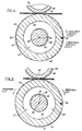
- the circular eccentrics have center axes or center lines 96 (seen in Figures 4 and 5) that are coaxial.
- the center lines of the eccentrics are spaced radially from the center axis 98 of the shaft 56 as is best seen in Figures 4 and 5. As seen in Figures 4 and 5, the radial spacing between the center axes of the eccentrics 96 and the shaft axis of rotation 98 is minute.
- Bearing assemblies 102, 104 are mounted over the circumferential surfaces of the eccentrics and engage against the interior surface 68 of the sleeve bore just inside the left and right ends 74, 76 of the sleeve.
- the bearing assemblies 102, 104 mount the anvil sleeve 54 for free rotation on the shaft 56.
- the axis of rotation of the anvil sleeve 54 is coaxial with the center axes 96 of the pair of eccentrics, and is parallel and spaced radially from the axis of rotation 98 of the shaft 56.
- the ball bearing assemblies shown in the drawing figures are illustrative only, and any suitable type of bearing may be employed to mount the sleeve on the eccentrics.
- the locking mechanism 66 is comprised of a screw threaded key 106 that is threaded into a complimentary screw threaded hole in a bearing box 108 fixed in the right hand frame member 18 of the press. By screw threading the key 106 into the hole, a head 110 of the key engages against a collar 112 of the handle assembly 86 and secures the collar against rotation relative to the press frame 18.
- the collar 112 is keyed to the shaft 56 and locking the collar against movement relative to the frame effectively locks the shaft against rotation relative to the frame.
- Turning the locking mechanism key 106 to back the key out of the threaded hole in the bearing box 108 releases the handle assembly 86 for rotation relative to the press frame 18. By gripping a lever 114 of the handle assembly 86 and turning the level about the center axis 98 of the shaft 56, the shaft is selectively and intermittently rotated relative to the press.
- the locking mechanism key 106 is engaged down on the handle assembly collar 112 to prevent the shaft 56 from rotating relative to the press.
- the drive roll gear 46 rotates the idler gear 48 freely on the shaft 56. Rotation of the idler gear drives the driven gear 52 and the die cutting cylinder 28.
- the bearing engagement between the end bearer rolls 26 of the die cutting cylinder 28 and the left and right bearer rolls 62, 64 of the anvil roll assembly cause the left and right bearer rolls 62, 64 to rotate freely on the shaft 56.
- the engagement of the axially projecting pin 78 of the anvil sleeve 54 in the radial slot 80 of the left bearer roll 62 transmits the rotation of the left bearer roll 62 to the anvil sleeve 54 and the sleeve rotates freely on the eccentrics 58.
- the radial extension of the slot 80 enables the pin 78 to move radially in the slot as the sleeve 54 is adjusted radially relative to the die cutting cylinder 28.
- providing the pin 78 in the anvil roll assembly of the invention is optional.
- the shaft 56 of the anvil roll assembly is manually rotated relative to the press.
- the shaft is incrementally rotated by a selectively operated motor (not shown).
- Manual rotation of the shaft 56 causes the eccentrics 58 to rotate about the shaft axis of rotation 98, with the center axes 96 of the eccentrics 58 rotating in a circular path around the shaft axis 98.
- the circular path travelled by the eccentric center axes 96 is concentric with the shaft axis of rotation 98 and has a radius equal to the radial spacing between the shaft axis 98 and the eccentric axes 96.
- the rotation of the eccentrics 58 about the shaft axis 98 causes the sleeve 54, rotatably supported on the eccentrics, to move radially relative to the die cutting cylinder of the press.
- Rotating the shaft 56 so that the maximum eccentricity of the eccentrics 58 is directed toward the die cutting cylinder 28 adjustably positions the cylindrical sleeve 54 in its closest adjusted position toward the cylinder.
- Rotating the shaft 180° so that the maximum eccentricity of the eccentrics is directed away from the die cutting cylinder adjustably positions the cylindrical sleeve in a radially adjusted position furthest away from the die cutting cylinder.
- the shaft is selectively and incrementally rotated only when adjusting the relative position of the sleeve to the die cutting cylinder and does not rotate during cutting operations of the press.
- the shaft 56 is rotated so that the eccentrics 58 are positioned at top dead center.
- the anvil sleeve 54 is moved radially upward as viewed in Figure 5, and the exterior surface 72 of the sleeve is positioned in its closest position to the die cutting cylinder 28.
- One complete rotation of the shaft 56 continuously adjusts the radial position of the anvil sleeve 54 relative to the die cutting cylinder 28 between a first position shown in Figure 5 where the sleeve is positioned closest to the cylinder, to a second position where the sleeve 54 is positioned furthest away from the cylinder 28, and then back again to the first position shown in Figure 5.
- the axes of rotation of the cylinder (not shown), the shaft 98, and the coaxial axes of the sleeve and eccentrics 96 all lie in one plane.
- the rotational axis of the sleeve and the center axes of the eccentrics 96 are positioned between the rotational axis of the cylinder (not shown) and the rotational axis of the shaft 98.
- the axis of rotation of the cylinder (not shown), the axis of rotation of the shaft 98, and the coaxial center axes 96 of the sleeve and eccentrics also lie in the same plane.
- the coaxial axis of rotation of the sleeve and the center axes of the eccentrics 96 are positioned on the opposite side of the shaft axis of rotation 98 from the axis of rotation of the cylinder (not shown).
- Figure 4 shows the positions of the eccentrics 58 in intermediate adjusted positions between the first and second positions of the shaft. In this position of the shaft, the eccentrics 58 project out to the right side of the anvil roll assembly as viewed in Figure 4. Only small portions of the eccentrics 58 extend above the shaft 56, and these small portions of the eccentrics elevate the anvil sleeve 54 a slight distance upward toward the die cutting cylinder 28. This same vertical adjustment of the anvil sleeve 54 would be produced by rotating the shaft 56 180° from the position shown in Figure 4 so that the eccentrics 58 project out from the left side of the shaft as viewed in Figure 4.
- eccentrics of the present invention have been described as being on a shaft that rotatably mounts an anvil sleeve, it should be understood that the eccentrics may also be employed on a shaft rotatably mounting a die cutting cylinder of the press. In such an assembly, the die cutting cylinder would then be radially adjustable toward and away from the anvil roll of the press.
Landscapes
- Life Sciences & Earth Sciences (AREA)
- Forests & Forestry (AREA)
- Engineering & Computer Science (AREA)
- Mechanical Engineering (AREA)
- Perforating, Stamping-Out Or Severing By Means Other Than Cutting (AREA)
- Nonmetal Cutting Devices (AREA)
- Crushing And Pulverization Processes (AREA)
- Press Drives And Press Lines (AREA)
Claims (11)
- Ein radial einstellbarer Amboßwalzen-Aufbau (14) zur Verwendung mit einer Schneideisenwalze (28) einer Rotationsschneideisen-Presse (12), wobei der Amboßwalzen-Aufbauaufweist.eine zylindrische Hülse (54) mit einer Innenbohrung (67),eine Welle (56), die sich durch die Innenbohrung (67) der Hülse (54) erstreckt, wobei die Welle (56) auf der Rotationsschneideisen-Presse (12) zur selektiven Rotation in Bezug auf die Presse montierbar ist, wobei die selektive Rotation der Welle (56) unabhängig von der Rotation der Schneideisenwalze (28) der Presse ist,eine Tragrolleneinrichtung (62), die auf der Welle (56) zur Aufrechterhaltung eines festen Abstandes zwischen den Rotationsachsen der Welle und der Schneideisenwalze (28) montiert ist, undmindestens einen Nocken-Aufbau (58, 102), der außermittig auf der Welle (56) im Innern der Hülsen-Innenbohrung (67) befestigt ist, wobei der Nocken-Aufbau (58, 102) eine radiale Einstellung der Hülse (54) in Bezug auf die Schneideisenwalze (28) und die Presse (12) als Reaktion auf eine Rotation der Welle (56) in irgendeine einer unendlichen Anzahl von Einzelpositionen in Bezug auf die Presse (12) bewirkt,
- Ein Amboßwalzen-Aufbau nach Anspruch 1,
dadurch gekennzeichnet,daß zwischen der Welle (56) und der Schneideisenwalze (28) keine Antriebsverbindungen vorhanden sind, die Rotationen der Schneidwalze auf die Welle übertragen. - Ein Amboßwalzen-Aufbau nach Anspruch 1 oder 2,
dadurch gekennzeichnet,daß der Nocken-Aufbau (58, 102) eine kreisförmige Nocke (58) mit einer Mittelachse aufweist, die parallel zu einer Mittelachse der Welle (56) und von dieser beabstandet ist. - Ein Amboßwalzen-Aufbau nach Anspruch 1, 2 oder 3,
dadurch gekennzeichnet,daß der Nocken-Aufbau (58, 102) die Hülse (54) zur freien Rotation auf der Welle (56) stützt. - Ein Amboßwalzen-Aufbau nach einem der Ansprüche 1 bis 4,
dadurch gekennzeichnet,daß zumindest eine Tragrolle (62) auf der Welle (56) zur freien Rotation auf der Welle (56) montiert ist,daß die Tragrolle (62) in antreibender Anlage an der Schneidwalze (28) und der Hülse (84) anliegt undeine Rotation der Schneidwalze (28) in eine Rotation der Hülse (54) umsetzt. - Ein Amboßwalzen-Aufbau nach Anspruch 5,
dadurch gekennzeichnet,daß die Hülse (54) mit einem Stift (78) versehen ist, der sich axial von der Hülse (54) erstreckt,daß die Tragrolle (62) mit einer Nut (80) versehen ist, unddaß sich der Stift (78) in die Nut erstreckt und in antreibender Anlage an der Hülse in einer Tragrolle (62) eingreift. - Ein Amboßwalzen-Aufbau nach einem der Ansprüche 1 bis 6,
dadurch gekennzeichnet,daß die radiale Position der Hülse (54) in Bezug auf die Schneideisenwalze (28) zwischen einer ersten Position, in welcher die Hülse (54) am nächsten zu der Walze (28) ist, und einer zweiten Position, in welcher die Hülse (54) am weitesten weg von der Walze (28) ist, einstellbar ist, unddaß die Hülse (54) von der ersten Position zu der zweiten Position durch Drehen der Welle (56) um 180° in Bezug auf die Schneidpresse (12) radial einstellbar ist. - Ein Amboßwalzen-Aufbau nach einem der Ansprüche 1 bis 7,
dadurch gekennzeichnet,daß die Welle (56) derart auf der Rotationsschneideisen-Presse (12) montiert ist, daß die Welle (56) in Bezug auf die Schneidpresse (12) manuell gedreht werden kann. - Ein Amboßwalzen-Aufbau nach Anspruch 8,
dadurch gekennzeichnet,daß eine manuelle Rotation der Welle (56) unabhängig von einer Rotation der Schneidwalze (28) und einer Rotation der Hülse (54) ist. - Ein Amboßwalzen-Aufbau nach einem der Ansprüche 1 bis 9,
dadurch gekennzeichnet,daß die Welle (56) auf der Rotationsschneideisen-Presse (12) zur relativen Rotation zu der Presse (12) montiert ist, unddaß die Rotation der Welle (56) die radiale Position der Hülse (54) in Bezug auf die Schneideisenwalze (28) einstellt. - Ein Amboßwalzen-Aufbau nach Anspruch 3,
dadurch gekennzeichnet,daß der Aufbau (58, 102) der kreisförmigen Nocke eine Mittelachse aufweist, die parallel zu den Rotationsachsen der Welle (56), der Hülse (54) und der Schneidwalze (28) und koaxial zur Rotationsachse der Hülse (54) ist.
Applications Claiming Priority (3)
| Application Number | Priority Date | Filing Date | Title |
|---|---|---|---|
| US685229 | 1991-04-12 | ||
| US07/685,229 US5083488A (en) | 1991-04-12 | 1991-04-12 | Radially adjustable anvil roll assembly for a rotary die cutting press |
| PCT/US1991/006961 WO1992018295A1 (en) | 1991-04-12 | 1991-09-24 | Radially adjustable anvil roll assembly for a rotary die cutting press |
Publications (3)
| Publication Number | Publication Date |
|---|---|
| EP0580576A1 EP0580576A1 (de) | 1994-02-02 |
| EP0580576A4 EP0580576A4 (en) | 1994-07-20 |
| EP0580576B1 true EP0580576B1 (de) | 1998-07-08 |
Family
ID=24751277
Family Applications (1)
| Application Number | Title | Priority Date | Filing Date |
|---|---|---|---|
| EP91918194A Expired - Lifetime EP0580576B1 (de) | 1991-04-12 | 1991-09-24 | Radial verstellbare gegenwalze für eine rotierende stanzvorrichtung |
Country Status (13)
| Country | Link |
|---|---|
| US (1) | US5083488A (de) |
| EP (1) | EP0580576B1 (de) |
| JP (1) | JP2885937B2 (de) |
| AT (1) | ATE168062T1 (de) |
| AU (1) | AU643924B2 (de) |
| CA (1) | CA2088504C (de) |
| DE (1) | DE69129754T2 (de) |
| DK (1) | DK0580576T3 (de) |
| ES (1) | ES2120963T3 (de) |
| GR (1) | GR3027687T3 (de) |
| MX (1) | MX9200208A (de) |
| NZ (1) | NZ240945A (de) |
| WO (1) | WO1992018295A1 (de) |
Cited By (3)
| Publication number | Priority date | Publication date | Assignee | Title |
|---|---|---|---|---|
| EP1974878A1 (de) | 2007-03-30 | 2008-10-01 | Wilhelm Aichele | Rotationsschneidevorrichtung |
| WO2015039750A1 (de) | 2013-09-23 | 2015-03-26 | Wink Stanzwerkzeuge Gmbh & Co. Kg | Vorrichtung zum rotationsstanzen |
| CN106625334A (zh) * | 2016-12-23 | 2017-05-10 | 宁波职业技术学院 | 一种快速可调压紧装置 |
Families Citing this family (45)
| Publication number | Priority date | Publication date | Assignee | Title |
|---|---|---|---|---|
| US5405486A (en) * | 1988-03-04 | 1995-04-11 | Noven Pharmaceuticals, Inc. | Apparatus for forming a transdermal drug device |
| US5156076A (en) * | 1991-05-21 | 1992-10-20 | Rosemann Richard R | Radially adjustable anvil roll assembly for a rotary die cutting press |
| US5189480A (en) * | 1992-01-31 | 1993-02-23 | Eastman Kodak Company | Apparatus for fixing a toner image including eccentrically mounted pressure relieving means |
| US5417132A (en) | 1993-01-19 | 1995-05-23 | Alan R. Pfaff | Rotary cutting dies |
| US5515757A (en) * | 1993-02-22 | 1996-05-14 | Corfine, Inc. | Rotary die cutters |
| US5598758A (en) * | 1993-07-22 | 1997-02-04 | Moore Business Forms, Inc. | Quick change cassette hole punch unit |
| ES2239488B1 (es) * | 2002-10-17 | 2007-02-16 | Imer, S.A. | Dispositivo de troquelado rotativo. |
| US20040074352A1 (en) * | 2002-10-21 | 2004-04-22 | Kimberly-Clark Worldwide, Inc. | Adjustable anvil for a flat bearer ring die |
| ES2232258B1 (es) * | 2002-11-28 | 2006-07-16 | Cimco, S.L. | Troqueladora rotativa. |
| SE527838C2 (sv) * | 2004-07-02 | 2006-06-20 | Sandvik Intellectual Property | En rotationskniv och en rotationsknivanordning försedd med en dylik rotationskniv |
| DE202004016214U1 (de) | 2004-10-20 | 2006-03-02 | Trumpf Werkzeugmaschinen Gmbh + Co. Kg | Restgitterzerschneidevorrichtung |
| SE527845C2 (sv) * | 2004-11-03 | 2006-06-20 | Sandvik Intellectual Property | En stödvals för en rotationsknivenhet och en rotationsknivenhet med en dylik stödvals |
| DE102006013397A1 (de) * | 2006-03-23 | 2007-10-04 | WINKLER + DüNNEBIER AG | Vorrichtung und Verfahren zum Ausschneiden von Flachmaterialzuschnitten aus Flachmaterialbogen |
| DE102006044610B4 (de) * | 2006-09-19 | 2008-11-20 | WINKLER+DüNNEBIER AG | Vorrichtung zum Schneiden und/oder Prägen eines Zuschnittes oder einer Materialbahn |
| DE102006051359A1 (de) * | 2006-10-27 | 2008-04-30 | Khs Ag | Schneidwerk für ein Etikettieraggregat sowie Etikettieraggregat mit einem solchen Schneidwerk |
| EP1925408B1 (de) * | 2006-11-27 | 2010-05-19 | WINK Stanzwerkzeuge GmbH & Co. KG | Stanzvorrichtung und Gegenstanzzylinder für eine Stanzvorrichtung |
| ES2333293B1 (es) * | 2008-06-13 | 2010-10-29 | Comercial Industrial Maquinaria Carton Ondulado S.L. | Cilindro contra-troquel para una maquina troqueladora de material laminar y metodo de montaje/extraccion de una mantilla. |
| IT1394271B1 (it) * | 2009-05-25 | 2012-06-06 | Ima Flavour S R L Ora Ima Ind S R L | Gruppo di compressione - incisione - taglio a rulli |
| US8216415B2 (en) * | 2009-09-04 | 2012-07-10 | Quinn Reed M | Manufacture of kinesiology tape |
| NL2005046C2 (nl) * | 2010-07-07 | 2012-01-10 | Jean Henry Robert Madern | Lagerbloksamenstel, alsmede walsinrichting voorzien van dergelijke lagerbloksamenstellen. |
| DE102011108505A1 (de) * | 2011-07-25 | 2013-01-31 | Gallus Druckmaschinen Gmbh | Vorrichtung zum Stanzen mit einstellbarem Zylinderabstand |
| US8869690B2 (en) * | 2012-09-07 | 2014-10-28 | Ming-Cheng Wang | Stationery machine |
| WO2014135266A1 (fr) * | 2013-03-07 | 2014-09-12 | Bobst Mex Sa | Procédé de réglage de l'intervalle radial entre deux outils, agencement de transformation d'un support, cassette, unité, et machine ainsi équipée |
| US20150135925A1 (en) * | 2013-11-20 | 2015-05-21 | Micro-Surface Finishing Products, Inc. | Rotary anvil |
| ITAR20130047A1 (it) * | 2013-12-04 | 2015-06-05 | Ultra System S R L | Rullo di controlama del tipo perfezionato, particolarmente per gruppi di taglio in macchine fustellatrici e simili. |
| US9956700B2 (en) * | 2014-01-16 | 2018-05-01 | American Crafts, L.C. | Crafting tool |
| BR112016028976B1 (pt) * | 2014-06-11 | 2021-10-19 | Curt G. Joa, Inc | Aparelho e método para desativação de elásticos em um laminado |
| WO2016070053A1 (en) * | 2014-10-31 | 2016-05-06 | Roto-Die Company, Inc. | Anvil roll and internal and external adjustment mechanisms therefor |
| USD765389S1 (en) | 2014-12-30 | 2016-09-06 | Medline Industries, Inc. | Dispenser |
| ITUB20153933A1 (it) * | 2015-09-28 | 2017-03-28 | Cartes S R L | Apparato per processare un materiale flessibile. |
| EP3380329B1 (de) * | 2015-11-23 | 2019-09-04 | Koenig & Bauer AG | Verfahren und vorrichtung mit modulen und trenneinrichtungen für bogenförmige substrate |
| US11292146B2 (en) * | 2016-07-25 | 2022-04-05 | International Cutting Die, Inc. | Cutting apparatus for minimizing deflection of a die cutter assembly |
| RS63391B1 (sr) * | 2016-11-15 | 2022-08-31 | Mespack Cloud Llc | Маšina za sečenje kesicа са оblikovanom spoljnom ivicom, postupak i kesica |
| CN110267782B (zh) * | 2017-03-29 | 2021-09-14 | 菱技精密工具株式会社 | 旋转模切机 |
| US11045966B2 (en) | 2017-05-01 | 2021-06-29 | Avery Dennison Retail Information Services, Llc | Stand-alone cutting apparatus |
| CN107599052A (zh) * | 2017-09-08 | 2018-01-19 | 苏州群创自动化设备有限公司 | 一种汽车仪表盘底盘孔位加工装置 |
| WO2019057254A1 (en) * | 2017-09-19 | 2019-03-28 | Mouentech I/S V/Phillip Larsen & Ole Bastian Riber | APPARATUS FOR TRACING, PUNCHING OR STAMPING |
| JP2019126852A (ja) * | 2018-01-22 | 2019-08-01 | 株式会社塚谷刃物製作所 | ロータリ加工装置 |
| US10857690B2 (en) | 2018-09-11 | 2020-12-08 | The Procter & Gamble Company | Method and apparatus for adjusting and maintaining a position of a cutting surface of a perforating apparatus |
| CN109500872A (zh) * | 2018-12-29 | 2019-03-22 | 无锡市人民医院 | 一种骨伤膏药切割装置 |
| CN109773866B (zh) * | 2019-02-07 | 2024-03-08 | 温州点成机械有限公司 | 一种分切机自动调刀装置 |
| IT201900016922A1 (it) * | 2019-09-23 | 2021-03-23 | Rotosystem S R L | Gruppo di taglio ad altezza variabile, particolarmente per macchina di taglio rotative o simili. |
| CN112248114A (zh) * | 2020-10-09 | 2021-01-22 | 深圳市合力泰光电有限公司 | 一种平压圆模切装置 |
| CN112850314A (zh) * | 2020-12-31 | 2021-05-28 | 豫鑫达(深圳)智能化设备有限责任公司 | 一种模切设备 |
| CN114227814B (zh) * | 2022-01-25 | 2025-05-13 | 廊坊纽特科技有限公司 | 一种圆压圆模切用辊机构 |
Family Cites Families (21)
| Publication number | Priority date | Publication date | Assignee | Title |
|---|---|---|---|---|
| DE1119210B (de) * | 1958-10-13 | 1961-12-14 | Automatik Inh H Hench | Kombinierte Abkantpresse und Schere mit Spalteinstellung |
| US3561658A (en) * | 1968-09-27 | 1971-02-09 | Fmc Corp | Nip roll assembly |
| US3683734A (en) * | 1970-06-25 | 1972-08-15 | Bhs Bayerische Berg | Roller bearing |
| US3720126A (en) * | 1970-12-11 | 1973-03-13 | Tension Envelope Corp | Die test stand |
| US3691810A (en) * | 1971-05-25 | 1972-09-19 | Tadeusz Sendzimir | Individual eccentric control for mill screwdown |
| US3803962A (en) * | 1972-06-23 | 1974-04-16 | G Koslow | Cut-to-length machine |
| US3855890A (en) * | 1972-12-20 | 1974-12-24 | Xerox Corp | Slitter/perforator apparatus |
| JPS5035420U (de) * | 1973-07-25 | 1975-04-15 | ||
| US3965786A (en) * | 1974-07-16 | 1976-06-29 | Moore Business Forms, Inc. | Rotary die cutter |
| US4130342A (en) * | 1977-05-31 | 1978-12-19 | Sperry Rand Corporation | Passive optical channel crossover, switch and bend structure |
| US4130042A (en) * | 1977-07-25 | 1978-12-19 | Avery International Corporation | Adjustable anvil roll for die-cutting labels |
| US4171655A (en) * | 1978-07-13 | 1979-10-23 | Western Printing Machinery Co. | Stabilized center-distance adjuster for rotary die cutters |
| US4226150A (en) * | 1978-08-15 | 1980-10-07 | Avery International Corporation | Deflectable bearer roll |
| DE2912458A1 (de) * | 1979-03-29 | 1980-10-09 | Winkler Duennebier Kg Masch | Rotationsstanze mit gegen die messerwalze abgestuetzter gegenwalze |
| US4325245A (en) * | 1980-03-13 | 1982-04-20 | Sherwood William L | Rolling mill stand |
| US4308776A (en) * | 1980-04-23 | 1982-01-05 | Philip Morris Incorporated | Web sectioning apparatus with adjustable knife engagement |
| US4548112A (en) * | 1984-07-20 | 1985-10-22 | Marquip, Inc. | Web cutting |
| CH673623A5 (de) * | 1987-06-19 | 1990-03-30 | Grapha Holding Ag | |
| US4922778A (en) * | 1987-10-16 | 1990-05-08 | Sky Aluminum Co., Ltd. | Apparatus for cutting metal sheet |
| US5001950A (en) * | 1988-10-14 | 1991-03-26 | Sequa Corporation | Rotary die cutter |
| US4962684A (en) * | 1989-04-07 | 1990-10-16 | Mowry Donald E | Cutting device for a board machine |
-
1991
- 1991-04-12 US US07/685,229 patent/US5083488A/en not_active Expired - Lifetime
- 1991-09-24 CA CA002088504A patent/CA2088504C/en not_active Expired - Lifetime
- 1991-09-24 AU AU87225/91A patent/AU643924B2/en not_active Expired
- 1991-09-24 DE DE69129754T patent/DE69129754T2/de not_active Expired - Lifetime
- 1991-09-24 JP JP3516771A patent/JP2885937B2/ja not_active Expired - Fee Related
- 1991-09-24 WO PCT/US1991/006961 patent/WO1992018295A1/en not_active Ceased
- 1991-09-24 EP EP91918194A patent/EP0580576B1/de not_active Expired - Lifetime
- 1991-09-24 AT AT91918194T patent/ATE168062T1/de not_active IP Right Cessation
- 1991-09-24 DK DK91918194T patent/DK0580576T3/da active
- 1991-09-24 ES ES91918194T patent/ES2120963T3/es not_active Expired - Lifetime
- 1991-12-11 NZ NZ240945A patent/NZ240945A/xx not_active IP Right Cessation
-
1992
- 1992-01-17 MX MX9200208A patent/MX9200208A/es unknown
-
1998
- 1998-08-20 GR GR980401863T patent/GR3027687T3/el unknown
Cited By (5)
| Publication number | Priority date | Publication date | Assignee | Title |
|---|---|---|---|---|
| EP1974878A1 (de) | 2007-03-30 | 2008-10-01 | Wilhelm Aichele | Rotationsschneidevorrichtung |
| WO2015039750A1 (de) | 2013-09-23 | 2015-03-26 | Wink Stanzwerkzeuge Gmbh & Co. Kg | Vorrichtung zum rotationsstanzen |
| DE102013110510A1 (de) | 2013-09-23 | 2015-03-26 | Rototechnix Sas | Vorrichtung zum Rotationsstanzen |
| CN106625334A (zh) * | 2016-12-23 | 2017-05-10 | 宁波职业技术学院 | 一种快速可调压紧装置 |
| CN106625334B (zh) * | 2016-12-23 | 2018-06-01 | 宁波职业技术学院 | 一种快速可调压紧装置 |
Also Published As
| Publication number | Publication date |
|---|---|
| WO1992018295A1 (en) | 1992-10-29 |
| CA2088504C (en) | 1995-07-25 |
| JP2885937B2 (ja) | 1999-04-26 |
| MX9200208A (es) | 1992-10-01 |
| DE69129754D1 (de) | 1998-08-13 |
| ES2120963T3 (es) | 1998-11-16 |
| EP0580576A1 (de) | 1994-02-02 |
| US5083488A (en) | 1992-01-28 |
| AU8722591A (en) | 1992-11-17 |
| ATE168062T1 (de) | 1998-07-15 |
| NZ240945A (en) | 1994-03-25 |
| EP0580576A4 (en) | 1994-07-20 |
| DE69129754T2 (de) | 1999-02-11 |
| JPH06506398A (ja) | 1994-07-21 |
| GR3027687T3 (en) | 1998-11-30 |
| DK0580576T3 (da) | 1999-04-19 |
| AU643924B2 (en) | 1993-11-25 |
Similar Documents
| Publication | Publication Date | Title |
|---|---|---|
| US5083488A (en) | Radially adjustable anvil roll assembly for a rotary die cutting press | |
| US5156076A (en) | Radially adjustable anvil roll assembly for a rotary die cutting press | |
| US4226150A (en) | Deflectable bearer roll | |
| EP1531975B1 (de) | Drehvorrichtung zum durchtrennen von bahnmaterialien | |
| JP2680041B2 (ja) | 打抜き機等のロールを調節するための組立体 | |
| EP0980751B1 (de) | Prägevorrichtung zur Herstellung von geprägten zweischichtigen Papierprodukten | |
| US4130042A (en) | Adjustable anvil roll for die-cutting labels | |
| EP2086845B1 (de) | Schneidwerk für ein etikettieraggregat sowie etikettieraggregat mit einem solchen schneidwerk | |
| CA1199572A (en) | Adjustable anvil roll | |
| US9079322B2 (en) | Device for the rotary diecutting of flat multi-layered goods | |
| US5189935A (en) | Rotary cutting die assembly | |
| US20140260851A1 (en) | Flexible die retaining system and method | |
| US20050120857A1 (en) | Rotary cutting tool with die plate position adjustment | |
| US5916343A (en) | Thermo-shrinking film cutting mechanism for a labeling machine | |
| US5778782A (en) | Device for processing webs or sheets of paper between two jointly operating working cylinders of a processing unit | |
| US4990215A (en) | Web-aligning apparatus | |
| US5857396A (en) | Slitting machine | |
| US5087318A (en) | Web-aligning apparatus | |
| US4793229A (en) | Multifunctional web rotary module | |
| EP3684567B1 (de) | Vorrichtung zum mattieren, stanzen oder prägen | |
| US3369436A (en) | Apparatus for processing a web of material | |
| JP4712260B2 (ja) | ウェブを加工するための力調節可能な回転装置 | |
| DK9700182U3 (de) | ||
| JPH0739627Y2 (ja) | 回転取付台案内装置 | |
| WO1992008584A1 (en) | Rotary cutting die assembly |
Legal Events
| Date | Code | Title | Description |
|---|---|---|---|
| PUAI | Public reference made under article 153(3) epc to a published international application that has entered the european phase |
Free format text: ORIGINAL CODE: 0009012 |
|
| 17P | Request for examination filed |
Effective date: 19930108 |
|
| AK | Designated contracting states |
Kind code of ref document: A1 Designated state(s): AT BE CH DE DK ES FR GB GR IT LI LU NL SE |
|
| A4 | Supplementary search report drawn up and despatched | ||
| AK | Designated contracting states |
Kind code of ref document: A4 Designated state(s): AT BE CH DE DK ES FR GB GR IT LI LU NL SE |
|
| 17Q | First examination report despatched |
Effective date: 19950404 |
|
| GRAG | Despatch of communication of intention to grant |
Free format text: ORIGINAL CODE: EPIDOS AGRA |
|
| GRAG | Despatch of communication of intention to grant |
Free format text: ORIGINAL CODE: EPIDOS AGRA |
|
| GRAG | Despatch of communication of intention to grant |
Free format text: ORIGINAL CODE: EPIDOS AGRA |
|
| GRAH | Despatch of communication of intention to grant a patent |
Free format text: ORIGINAL CODE: EPIDOS IGRA |
|
| GRAH | Despatch of communication of intention to grant a patent |
Free format text: ORIGINAL CODE: EPIDOS IGRA |
|
| GRAA | (expected) grant |
Free format text: ORIGINAL CODE: 0009210 |
|
| AK | Designated contracting states |
Kind code of ref document: B1 Designated state(s): AT BE CH DE DK ES FR GB GR IT LI LU NL SE |
|
| REF | Corresponds to: |
Ref document number: 168062 Country of ref document: AT Date of ref document: 19980715 Kind code of ref document: T |
|
| REG | Reference to a national code |
Ref country code: CH Ref legal event code: EP |
|
| REF | Corresponds to: |
Ref document number: 69129754 Country of ref document: DE Date of ref document: 19980813 |
|
| ITF | It: translation for a ep patent filed | ||
| REG | Reference to a national code |
Ref country code: CH Ref legal event code: NV Representative=s name: PATENTANWALTSBUERO JEAN HUNZIKER |
|
| REG | Reference to a national code |
Ref country code: ES Ref legal event code: FG2A Ref document number: 2120963 Country of ref document: ES Kind code of ref document: T3 |
|
| ET | Fr: translation filed | ||
| REG | Reference to a national code |
Ref country code: DK Ref legal event code: T3 |
|
| PLBE | No opposition filed within time limit |
Free format text: ORIGINAL CODE: 0009261 |
|
| STAA | Information on the status of an ep patent application or granted ep patent |
Free format text: STATUS: NO OPPOSITION FILED WITHIN TIME LIMIT |
|
| 26N | No opposition filed | ||
| REG | Reference to a national code |
Ref country code: GB Ref legal event code: IF02 |
|
| PGFP | Annual fee paid to national office [announced via postgrant information from national office to epo] |
Ref country code: CH Payment date: 20100930 Year of fee payment: 20 Ref country code: ES Payment date: 20100927 Year of fee payment: 20 |
|
| PGFP | Annual fee paid to national office [announced via postgrant information from national office to epo] |
Ref country code: AT Payment date: 20100901 Year of fee payment: 20 Ref country code: FR Payment date: 20100930 Year of fee payment: 20 |
|
| PGFP | Annual fee paid to national office [announced via postgrant information from national office to epo] |
Ref country code: GR Payment date: 20100929 Year of fee payment: 20 Ref country code: GB Payment date: 20100927 Year of fee payment: 20 |
|
| PGFP | Annual fee paid to national office [announced via postgrant information from national office to epo] |
Ref country code: DK Payment date: 20100928 Year of fee payment: 20 Ref country code: NL Payment date: 20100924 Year of fee payment: 20 |
|
| PGFP | Annual fee paid to national office [announced via postgrant information from national office to epo] |
Ref country code: BE Payment date: 20100927 Year of fee payment: 20 Ref country code: DE Payment date: 20100929 Year of fee payment: 20 Ref country code: LU Payment date: 20101008 Year of fee payment: 20 |
|
| PGFP | Annual fee paid to national office [announced via postgrant information from national office to epo] |
Ref country code: SE Payment date: 20100929 Year of fee payment: 20 Ref country code: IT Payment date: 20100928 Year of fee payment: 20 |
|
| REG | Reference to a national code |
Ref country code: DE Ref legal event code: R071 Ref document number: 69129754 Country of ref document: DE |
|
| REG | Reference to a national code |
Ref country code: DE Ref legal event code: R071 Ref document number: 69129754 Country of ref document: DE |
|
| BE20 | Be: patent expired |
Owner name: *STANLEY MELVIN C. Effective date: 20110924 Owner name: *ROSEMANN THOMAS J. Effective date: 20110924 |
|
| REG | Reference to a national code |
Ref country code: CH Ref legal event code: PL |
|
| REG | Reference to a national code |
Ref country code: NL Ref legal event code: V4 Effective date: 20110924 |
|
| REG | Reference to a national code |
Ref country code: DK Ref legal event code: EUP |
|
| REG | Reference to a national code |
Ref country code: GB Ref legal event code: PE20 Expiry date: 20110923 |
|
| REG | Reference to a national code |
Ref country code: SE Ref legal event code: EUG |
|
| PG25 | Lapsed in a contracting state [announced via postgrant information from national office to epo] |
Ref country code: GB Free format text: LAPSE BECAUSE OF EXPIRATION OF PROTECTION Effective date: 20110923 |
|
| PG25 | Lapsed in a contracting state [announced via postgrant information from national office to epo] |
Ref country code: NL Free format text: LAPSE BECAUSE OF EXPIRATION OF PROTECTION Effective date: 20110924 |
|
| PG25 | Lapsed in a contracting state [announced via postgrant information from national office to epo] |
Ref country code: DE Free format text: LAPSE BECAUSE OF EXPIRATION OF PROTECTION Effective date: 20110925 |
|
| REG | Reference to a national code |
Ref country code: ES Ref legal event code: FD2A Effective date: 20130723 |
|
| PG25 | Lapsed in a contracting state [announced via postgrant information from national office to epo] |
Ref country code: ES Free format text: LAPSE BECAUSE OF EXPIRATION OF PROTECTION Effective date: 20110925 |