EP0580703B1 - Überlappende bleche - Google Patents
Überlappende bleche Download PDFInfo
- Publication number
- EP0580703B1 EP0580703B1 EP92909147A EP92909147A EP0580703B1 EP 0580703 B1 EP0580703 B1 EP 0580703B1 EP 92909147 A EP92909147 A EP 92909147A EP 92909147 A EP92909147 A EP 92909147A EP 0580703 B1 EP0580703 B1 EP 0580703B1
- Authority
- EP
- European Patent Office
- Prior art keywords
- weld
- metal plate
- heads
- metal
- welding
- Prior art date
- Legal status (The legal status is an assumption and is not a legal conclusion. Google has not performed a legal analysis and makes no representation as to the accuracy of the status listed.)
- Expired - Lifetime
Links
Images


Classifications
-
- B—PERFORMING OPERATIONS; TRANSPORTING
- B23—MACHINE TOOLS; METAL-WORKING NOT OTHERWISE PROVIDED FOR
- B23K—SOLDERING OR UNSOLDERING; WELDING; CLADDING OR PLATING BY SOLDERING OR WELDING; CUTTING BY APPLYING HEAT LOCALLY, e.g. FLAME CUTTING; WORKING BY LASER BEAM
- B23K37/00—Auxiliary devices or processes, not specially adapted for a procedure covered by only one of the other main groups of this subclass
- B23K37/04—Auxiliary devices or processes, not specially adapted for a procedure covered by only one of the other main groups of this subclass for holding or positioning work
- B23K37/0408—Auxiliary devices or processes, not specially adapted for a procedure covered by only one of the other main groups of this subclass for holding or positioning work for planar work
-
- B—PERFORMING OPERATIONS; TRANSPORTING
- B23—MACHINE TOOLS; METAL-WORKING NOT OTHERWISE PROVIDED FOR
- B23K—SOLDERING OR UNSOLDERING; WELDING; CLADDING OR PLATING BY SOLDERING OR WELDING; CUTTING BY APPLYING HEAT LOCALLY, e.g. FLAME CUTTING; WORKING BY LASER BEAM
- B23K37/00—Auxiliary devices or processes, not specially adapted for a procedure covered by only one of the other main groups of this subclass
- B23K37/003—Cooling means for welding or cutting
-
- B—PERFORMING OPERATIONS; TRANSPORTING
- B23—MACHINE TOOLS; METAL-WORKING NOT OTHERWISE PROVIDED FOR
- B23K—SOLDERING OR UNSOLDERING; WELDING; CLADDING OR PLATING BY SOLDERING OR WELDING; CUTTING BY APPLYING HEAT LOCALLY, e.g. FLAME CUTTING; WORKING BY LASER BEAM
- B23K9/00—Arc welding or cutting
- B23K9/04—Welding for other purposes than joining, e.g. built-up welding
- B23K9/042—Built-up welding on planar surfaces
Definitions
- This invention relates to a weld overlaying apparatus and a method of overlaying weld metal onto metal plates and in particular it relates to plates of the type in which the metal material such as mild steel used in the production of various apparatus is faced with a layer of weld metal deposited by welding means to provide a hard facing or alloy cladding.
- Overlaying of weld metal is already well known in the art and is used for instance in supplying tips to tools such as shears and the like used in agriculture and it is also known to overlay plates by welding. Overlaying may also be used to face metal with another metal or alloy.
- weld overlaying Another problem exists with weld overlaying is that in the sheet material some portions of the sheet are heated more than others because two welding heads pass over the same area and this gives an uneven thickness of weld metal overlay and perhaps some change to the metallurgical structure of the underlying metal.
- German Patent DE-A-2131142 considered to be the closest state of the art document, describes a weld overlaying apparatus comprising drive means (50) to draw a metal workpiece (40) substantially horizontally through the apparatus and a plurality of welding heads (52 to 56) arranged on a common oscillating carrier to oscillate for oscillating movement transverse to the direction of travel of the metal workpiece.
- This present invention provides solutions to the above problems or at least provides an alternative construction of machine.
- the invention is said to reside in a weld overlaying apparatus comprising drive means to draw a metal plate substantially horizontally through the apparatus, and a plurality of welding heads arranged on a common oscillating carrier to oscillate for oscillating movement transverse to the direction of travel of the metal plate, characterised by a wheel assembly positioned so as to be under the metal plate in use, wherein the wheel assembly induces a slight upward convexity in the metal plate under the welding heads so as to accurately position the metal plate with respect to the welding heads.
- the wheel assembly is positioned under the welding head.
- the wheel assembly may include water cooling means whereby to cool the underside of the metal plate at the point of welding.
- the wheel assembly may include a plurality of discs spaced apart on a central axis and the water cooling means may comprise water spray heads between the discs and adapted to direct a spray of water towards the region the weld heads to strike the underside of the metal plate when in use and hence cool the plate.
- the weld overlaying apparatus may further include flux and metal alloy powder addition means to apply a layer of flux and metal powder onto the surface of the metal sheet upstream of the weld head so that the flux and metal alloy powder can take part in the weld application process.
- the type of flux and metal alloy powder used will depend upon the required hardness and/or metallurgical composition of the weld metal overlay.
- a slag breaking wheel downstream from the welding heads, the slag breaking wheel including a plurality of discs on a transverse axis and also including suction means to remove cracked slag.
- the drive means may include drive rollers positioned above and below the line of travel of the metal plate and adapted to bear onto both upper and lower surfaces of the metal plate to securely hold the metal plate and move it forward as required.
- the drive means may be adapted to move intermittently the metal plate at the same time as the oscillation of the weld head reverses direction in its transverse travel. By this means the metal plate will be stationary while the plurality of weld heads transverse the plate but the plate moves forward when the weld heads reverse direction.
- Each of the weld heads may include a continuously fed wire electrode and the weld head may include means to drive the wire electrodes as they are consumed in the welding process.
- adjacent weld heads may be transversely offset from each other with respect to the direction of travel of the oscillating carrier.
- transverse offset in the weld heads there will be limited localised heating caused by adjacent weld heads passing over or near the same point on the metal please when each weld head reverses direction.
- the adjacent weld heads may be offset by a distance which is equivalent to half the distance that the plate is intermittently moved forward during operation of the welding apparatus.
- the invention is said to reside in a method of overlaying weld metal onto a surface of a longitudinally moving metal plate for the purpose of hard facing or alloy cladding of the metal plate comprising the steps of laying down a layer of weld metal onto the metal surface by means of transversely reciprocating a set of weld heads across the longitudinally moving metal surface characterised by imparting a slight convexity to the metal plate as it passes under the weld heads by means of a wheel assembly under the metal plate whereby to accurately position the metal plate with respect to the weld heads.
- a method according to this invention may further include the steps of laying down a layer of flux and metal alloy powder onto the surface of the metal plate before the plate passes under the weld heads.
- the longitudinally moving of the metal plate may be incrementally moved forward at the same time that the oscillatory movement of the weld head reverses direction.
- the method of this invention may further include the step of cooling the metal plate from underneath the plate in the region of the weld heads by means of water spray jets associated with the wheel assembly.
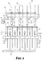
- the weld overlaying apparatus of the present invention comprises upstream drive means 1 and downstream drive means 2 driven from a common drive shaft 3 by means of chains 4 and 5.
- Upstream drive means 1 comprises lower drive wheel 6 and upper drive wheel 7 driven by a drive chain 8 with the metal plate 10 positioned between the upper and lower drive wheels 7 and 6.
- Idler wheel 11 and tensioning idler wheel 12 are provided to ensure that the chain 8 drives both wheels in their required direction.
- the downstream drive assembly 2 comprises two lower drive wheels 15 and 16 and a single upper drive wheel 17.
- Drive chain 20 passes over the drive wheel 15, 16 and 17 and over idler wheels 21 and 22 and tensioning idler wheel 23 again to keep the chain in tension and ensure that all the drive wheels are driven in the same direction.
- metal plate 10 passes over the lower drive wheels 15 and 16 and under the drive wheel 17.
- the metal plate passes under a weld head assembly 30 and over a wheel assembly 31 between the upstream drive assembly 1 and the downstream drive assembly 2.
- the metal plate With drive means both upstream and downstream from the welding station the metal plate can be kept in tension which will hold to reduce distortion during welding.
- the wheel assembly 31 which can be seen more easily in FIG. 3 comprises a central axis 35 supported on bearings 36 and a number of annular discs 37 supported on the shaft 35.
- the discs 37 bear on the underside of the metal plate 10 and induce a slight convexity into the metal plate.
- a water spray assembly 38 supplied from a water manifold 39 sprays water between adjacent discs 37 to cool the underside of the metal plate 10.
- wheel assembly may be used to provide the slight convexity.
- One embodiment may be a plurality of small wheels arranged in an arc to bear up under the steel plate.
- the weld head assembly 30 comprises a reciprocating carrier 40 supported by means (not shown) which are caused to reciprocate transversely to the direction of travel of the metal plate by means of a motor 41 and crank assembly 42.
- a motor 41 and crank assembly 42 In this embodiment four weld heads 43 are supported by bracket means 44 from the carrier 40.
- weld heads depending upon the width of the plate to be overlayed and drive means such as a linear motor may be used.
- the welding heads in this embodiment are of the continuously wire fed type and wire feed motor 46 drives wire feed drives 47 which feed wire 48 through the weld heads so that respective welding tips 49 are a desired distance from the surface of the metal plate 10. Electricity is supplied to the weld head by means of cables 50.
- the negative or ground electrode for the welding arrangement 75 may be positioned on the apparatus to bear underneath the metal plate 10 to be in contact with the metal plate to ensure good electrical conductivity and the earth by means of cable 76.
- the flux and metal alloy powder applying means Just upstream from the welding heads is the flux and metal alloy powder applying means.
- This includes a hopper 60 which has a discharge end 62 which is spaced apart from a flux and metal alloy powder applying roller 61 so that a small amount of flux and metal powder exits through the hopper end 62 and is positioned on the roller 61 and as the roller 61 is driven (by means not shown) the powder is deposited onto the metal plate 10.
- the welding slag removing station 70 Immediately downstream from the weld heads 70 is the welding slag removing station 70.
- the welding slag removal station 70 includes a slag cracking wheel 71 which comprises a plurality of annular discs fitted onto a central boss and which are run onto the weld surface of the metal arc of welding which cause any slag on to the surface to crack.
- the cracks slag is drawn by means of vacuum suction arrangement 72 before the slag cracking wheel and 73 after the slag cracking wheel.
- the path of travel of the weld heads over the surface of the metal plate 10 is a series of oscillatory or side to side movements.
- Adjacent weld heads 80 and 81 are spaced apart in the direction of travel of the metal plate by distance 82 which is approximately half the spacing between adjacent oscillations of the weld heads. It will be seen that by this offset spacing the paths of adjacent welding heads do not cross and hence localised points of over-heating will not occur.
- the method of operation of the weld metal overlaying apparatus is as follows.
- a metal plate 10 is fed into the apparatus and the drive means 1 and 2 are driven in such a manner so as to keep the metal plate in tension where it passes over the wheel assembly 31.
- the metal plate also has a slightly induced convexity between the flux and metal powder adding roller 61 and the slag braking roller 71.
- the convexity is carried by the wheel assembly 30 which bears on the under side of the metal plate between the rollers 61 and 71. This slight convexity ensures that a fixed distance is maintained between the upper surface of the metal plate 10 and the tip of the welding electrode 49 whereby ensuring a constant arc size and hence constant depth of weld and consumption of the wire electrode 48.
Landscapes
- Engineering & Computer Science (AREA)
- Physics & Mathematics (AREA)
- Mechanical Engineering (AREA)
- Optics & Photonics (AREA)
- Plasma & Fusion (AREA)
- Arc Welding In General (AREA)
- Butt Welding And Welding Of Specific Article (AREA)
- Laminated Bodies (AREA)
- Polishing Bodies And Polishing Tools (AREA)
- Glass Compositions (AREA)
- Table Devices Or Equipment (AREA)
- Manufacturing Of Electric Cables (AREA)
- Resistance Welding (AREA)
Claims (14)
- Apparat für Auftragsschweißen mit einer Antriebsvorrichtung (1, 2), um eine Metallplatte (10) im wesentlichen horizontal durch das Gerät zu ziehen und einer Vielzahl von Schweißköpfen (43), welche auf einem gemeinsamen, oszillierenden Träger (40) angeordnet sind, um quer zur Bewegungsrichtung der Metallplatte (10) zu schwingen, gekennzeichnet durch eine Räderanordnung (31), die derart angeordnet ist, daß sie sich unterhalb der benutzten Metallplatte befindet, wobei die Räderanordnung (31) eine leichte nach oben gerichtete konvexe Biegung in der Metallplatte erzeugt, so daß die Metallplatte akkurat bezüglich der Schweißköpfe (43) positioniert wird.
- Apparat für Auftragsschweißen gemäß Anspruch 1, wobei die Räderanordnung (31) mit einer Wasserkühlungsvorrichtung (38) versehen ist, welche zur Kühlung der Unterseite der Metallplatte am Schweißpunkt dient.
- Apparat für Auftragsschweißen gemäß Anspruch 2, wobei die Räderanordnung (31) aus einer Vielzahl von Scheiben (37) besteht, welche in Abständen auf einer zentralen Achse (35) angeordnet sind und deren Laufflächen die benutzte Metallplatte (10) tragen, und wobei die Wasserkühlungsvorrichtung Wassersprühköpfe (38) zwischen den Scheiben aufweist, die derart ausgelegt sind, um Wasser in Richtung der Schweißköpfe (43) zu sprühen.
- Apparat für Auftragsschweißen gemäß Anspruch 1, zusätzlich ausgestattet mit einer Vorrichtung zur Zugabe von Schweiß- und Metallegierungspulver (60) zum Aufbringen einer Schicht von Schweiß- und Metallpulver auf die Oberfläche der Metallplatte (10), auf der das Auftragsschweißen erfolgen soll.
- Apparat für Auftragsschweißen gemäß Anspruch 1, zusätzlich ausgestattet mit einem Schlackenbrechrat 71) hinter den Schweißköpfen, wobei das Schlackenbrechrat eine Vielzahl von Scheiben auf einer transversalen Achse und außerdem eine Saugvorrichtung (72, 73) zum Entfernen der abgebrochenen Schlacke aufweist.
- Apparat für Auftragsschweißen gemäß Anspruch 1, wobei die Antriebsvorrichtung Antriebsrollen (6, 7, 15, 16, 17) umfaßt, die oberhalb und unterhalb der Verfahrebene der Metallplatte so angeordnet und eingestellt sind, daß die Rollen auf der Metallplatte aufliegen.
- Apparat für Auftragsschweißen gemäß Anspruch 6, welcher mit jeweils einer Antriebsvorrichtung vor (1) und hinter (2) den Schweißköpfen (43) ausgestattet ist, wodurch die Metallplatte zwischen den Antriebsvorrichtungen vor (1) und hinter (2) den Schweißköpfen (43) unter Spannung gehalten wird.
- Apparat für Auftragsschweißen gemäß Anspruch 1, wobei die Antriebsvorrichtungen (1, 2) so ausgelegt sind, daß sie die Metallplatte (10) intermittierend gleichzeitig mit der Umkehrbewegung der oszillierenden Schweißköpfe (43) bewegen.
- Apparat für Auftragsschweißen gemäß Anspruch 1, wobei jeder der Schweißköpfe (43) eine kontinuierlich zugeführte Drahtelektrode (48) aufweist und die Schweißköpfe mit Antriebsvorrichtungen (46, 47) für die Drahtelektroden versehen sind.
- Apparat für Auftragsschweißen gemäß Anspruch 1, wobei nebeneinander liegende Schweißköpfe (43) quer zur Laufrichtung des oszillierenden Trägers (40) versetzt angeordnet sind.
- Methode zum Auftragen von Schweißmetall auf die Oberfläche einer sich in Längsrichtung bewegenden Metallplatte (10), zum Zwecke des Aufschweißens von Hartmetall oder zum Auftragsschweißen von Legierungen auf die Metallplatte mit dem Schritt des Auftragens einer Schicht von Schweißmetall auf die Metallplatte, und zwar durch transversale Hin- und Herbewegungen eines Satzes von Schweißköpfen (43) über der sich in Längsrichtung bewegenden Oberfläche der Metallplatte, dadurch gekennzeichnet, daß der Metallplatte eine leichte konvexe Biegung verliehen wird, während es mit Hilfe der unter der Metallplatte angeordneten Räderanordnung (31) unter den Schweißköpfen hindurchgezogen wird, so daß die Metallplatte in die akkurate Position im Verhältnis zu den Schweißköpfen gebracht wird.
- Methode gemäß Anspruch 11, welche außerdem den Schritt der Kühlung der Metallplatte von der Unterseite her im Bereich der Schweißköpfe mit Hilfe von Sprühköpfen (38) aufweist, die der Räderanordnung zugeordnet sind.
- Methode gemäß Anspruch 11, welche außerdem den Schritt des Aufbringens einer Schicht von Schweiß- und Metallegierungspulver auf die Oberfläche der Metallplatte aufweist, bevor die Platte unter den Schweißköpfen (43) hindurchgezogen wird.
- Methode gemäß Anspruch 11, die weiterhin den Schritt des intermittierenden Vorwärtsbewegens der Metallplatte in Längsrichtung gleichzeitig mit dem Umkehren der Richtung der oszillierenden Bewegung der Schweißköpfe aufweist.
Applications Claiming Priority (3)
| Application Number | Priority Date | Filing Date | Title |
|---|---|---|---|
| AUPK570091 | 1991-04-18 | ||
| AU5700/91 | 1991-04-18 | ||
| PCT/AU1992/000167 WO1992018283A1 (en) | 1991-04-18 | 1992-04-15 | Overlaying of plates |
Publications (3)
| Publication Number | Publication Date |
|---|---|
| EP0580703A1 EP0580703A1 (de) | 1994-02-02 |
| EP0580703A4 EP0580703A4 (de) | 1994-02-09 |
| EP0580703B1 true EP0580703B1 (de) | 1997-11-05 |
Family
ID=3775348
Family Applications (1)
| Application Number | Title | Priority Date | Filing Date |
|---|---|---|---|
| EP92909147A Expired - Lifetime EP0580703B1 (de) | 1991-04-18 | 1992-04-15 | Überlappende bleche |
Country Status (11)
| Country | Link |
|---|---|
| US (1) | US5362937A (de) |
| EP (1) | EP0580703B1 (de) |
| JP (1) | JP3025975B2 (de) |
| KR (1) | KR100254181B1 (de) |
| AT (1) | ATE159879T1 (de) |
| BR (1) | BR9205898A (de) |
| CA (1) | CA2108274C (de) |
| DE (1) | DE69223047T2 (de) |
| GR (1) | GR3026083T3 (de) |
| RU (1) | RU2094195C1 (de) |
| WO (1) | WO1992018283A1 (de) |
Families Citing this family (24)
| Publication number | Priority date | Publication date | Assignee | Title |
|---|---|---|---|---|
| DE29612421U1 (de) * | 1996-07-17 | 1996-10-17 | Fritz Freier Bergbaumaschinen GmbH, 98617 Obermaßfeld-Grimmenthal | Auflagetisch für die Hartlegierungsauftragsschweißung von Stahlplatten |
| JP3481797B2 (ja) * | 1996-10-03 | 2003-12-22 | 片山特殊工業株式会社 | 電池電極用基板の製造方法および電池電極用基板 |
| IT1295384B1 (it) | 1997-10-23 | 1999-05-12 | Snam Progetti | Rivestimento protettivo di apparecchiature a pressione utilizzabili in processi per la sintesi dell'urea |
| AUPR153100A0 (en) * | 2000-11-20 | 2000-12-14 | Kostecki, Gene | Improvements in bulk materials transport containers |
| US20050126056A1 (en) * | 2000-11-20 | 2005-06-16 | Gene Kostecki | Bulk materials transport containers |
| EP1677939B1 (de) * | 2003-10-21 | 2010-12-08 | Welding Alloys Limited | Herstellung dünner oberflächengehärteter platten |
| US8637127B2 (en) | 2005-06-27 | 2014-01-28 | Kennametal Inc. | Composite article with coolant channels and tool fabrication method |
| RU2432445C2 (ru) | 2006-04-27 | 2011-10-27 | Ти Ди Уай Индастриз, Инк. | Модульное буровое долото с неподвижными режущими элементами, корпус данного модульного бурового долота и способы их изготовления |
| EP2078101A2 (de) | 2006-10-25 | 2009-07-15 | TDY Industries, Inc. | Artikel mit erhöhter widerstandsfähigkeit gegenüber thermischem cracken |
| GB0803421D0 (en) * | 2008-02-26 | 2008-04-02 | Pipeline Tech Ltd | Method of forming a surface profile on a tubular component |
| US8790439B2 (en) | 2008-06-02 | 2014-07-29 | Kennametal Inc. | Composite sintered powder metal articles |
| US8025112B2 (en) | 2008-08-22 | 2011-09-27 | Tdy Industries, Inc. | Earth-boring bits and other parts including cemented carbide |
| US9512938B2 (en) | 2008-12-23 | 2016-12-06 | Pipeline Technique Limited | Method of forming a collar on a tubular component through depositing of weld metal and machining this deposit into a collar |
| US9050673B2 (en) | 2009-06-19 | 2015-06-09 | Extreme Surface Protection Ltd. | Multilayer overlays and methods for applying multilayer overlays |
| RU2420610C1 (ru) * | 2009-09-23 | 2011-06-10 | Общество с ограниченной ответственностью "Производственное предприятие Турбинаспецсервис" | Способ формирования дискретного наплавочного покрытия на пере лопатки турбомашины |
| US9643236B2 (en) | 2009-11-11 | 2017-05-09 | Landis Solutions Llc | Thread rolling die and method of making same |
| GB201106238D0 (en) * | 2011-04-13 | 2011-05-25 | Linde Ag | Weld cladding |
| US20120325779A1 (en) * | 2011-06-22 | 2012-12-27 | Caterpillar, Inc. | Alloy Depositing Machine And Method Of Depositing An Alloy Onto A Workpiece |
| US8800848B2 (en) | 2011-08-31 | 2014-08-12 | Kennametal Inc. | Methods of forming wear resistant layers on metallic surfaces |
| US9016406B2 (en) | 2011-09-22 | 2015-04-28 | Kennametal Inc. | Cutting inserts for earth-boring bits |
| JP2017205803A (ja) * | 2016-05-20 | 2017-11-24 | 株式会社フジコー | 溶接ライナーの製造方法および製造装置、ならびに溶接ライナー |
| US10493571B1 (en) * | 2018-09-17 | 2019-12-03 | Andrew Kostecki | Fused overlay plate and method |
| WO2020060969A1 (en) * | 2018-09-17 | 2020-03-26 | Andrew Kostecki | Fused overlay plate and method |
| US11712746B1 (en) | 2019-07-16 | 2023-08-01 | Andrew Kostecki | Wire feeder assembly |
Family Cites Families (17)
| Publication number | Priority date | Publication date | Assignee | Title |
|---|---|---|---|---|
| DE273020C (de) * | 1913-04-20 | |||
| US2726617A (en) * | 1952-05-09 | 1955-12-13 | American Viscose Corp | Mobile bonding machine |
| US2813190A (en) * | 1954-11-01 | 1957-11-12 | Air Reduction | Multiple arc welding |
| US3185814A (en) * | 1961-12-30 | 1965-05-25 | Siemens Ag | Method and apparatus for overlay welding |
| US3573420A (en) * | 1968-12-23 | 1971-04-06 | Arcos Corp | Process and apparatus for nonconsumable electrode overlay welding |
| US3611541A (en) * | 1970-01-30 | 1971-10-12 | Smith International | Tool joint rebuilding |
| DE2131142A1 (de) * | 1970-07-27 | 1972-02-03 | Stoody Comp | System zur Auflage von Schweissschichten auf Metalloberflaechen |
| DE2135149A1 (de) * | 1971-07-14 | 1973-02-01 | Demag Ag | Auftragsschweissvorrichtung |
| US4237362A (en) * | 1978-09-28 | 1980-12-02 | Tapco International, Inc. | Method of producing hardfaced plate |
| EP0107343B1 (de) * | 1982-09-21 | 1987-05-06 | Inoue-Japax Research Incorporated | Entladungsbeschichtungsverfahren und Vorrichtung dafür |
| US4521664A (en) * | 1982-10-26 | 1985-06-04 | Teledyne, Inc. | Process and apparatus for surfacing with high deposition and low dilution |
| FR2548569B1 (fr) * | 1983-07-08 | 1986-12-26 | Prunier Robert | Procede pour revetir une surface metallique par un metal d'apport par arc electrique et appareil pour la mise en oeuvre de ce procede |
| CA1215129A (en) * | 1983-11-16 | 1986-12-09 | Donald J. Reilly | Ingot mould repair method |
| GB8611918D0 (en) * | 1986-05-16 | 1986-06-25 | Redman D H G | Slide mechanism |
| JPS63183774A (ja) * | 1986-09-30 | 1988-07-29 | Maruma Jusharyo Kk | 肉盛溶接機のスラグ除去装置 |
| DD273020A1 (de) * | 1988-06-20 | 1989-11-01 | Zentralinstitut Schweiss | Vorrichtung zum flaechenhaften auftragsschweissen an randzonen von bauteilen |
| JP5931430B2 (ja) | 2011-12-21 | 2016-06-08 | 三菱重工業株式会社 | 空気調和機 |
-
1992
- 1992-04-15 AT AT92909147T patent/ATE159879T1/de active
- 1992-04-15 RU RU9293058293A patent/RU2094195C1/ru active
- 1992-04-15 KR KR1019930703160A patent/KR100254181B1/ko not_active Expired - Fee Related
- 1992-04-15 WO PCT/AU1992/000167 patent/WO1992018283A1/en not_active Ceased
- 1992-04-15 US US08/137,115 patent/US5362937A/en not_active Expired - Lifetime
- 1992-04-15 JP JP4508370A patent/JP3025975B2/ja not_active Expired - Fee Related
- 1992-04-15 DE DE69223047T patent/DE69223047T2/de not_active Expired - Lifetime
- 1992-04-15 BR BR9205898A patent/BR9205898A/pt not_active IP Right Cessation
- 1992-04-15 CA CA002108274A patent/CA2108274C/en not_active Expired - Lifetime
- 1992-04-15 EP EP92909147A patent/EP0580703B1/de not_active Expired - Lifetime
-
1998
- 1998-02-05 GR GR980400250T patent/GR3026083T3/el unknown
Also Published As
| Publication number | Publication date |
|---|---|
| EP0580703A4 (de) | 1994-02-09 |
| US5362937A (en) | 1994-11-08 |
| DE69223047D1 (de) | 1997-12-11 |
| WO1992018283A1 (en) | 1992-10-29 |
| CA2108274A1 (en) | 1992-10-19 |
| ATE159879T1 (de) | 1997-11-15 |
| BR9205898A (pt) | 1994-07-26 |
| CA2108274C (en) | 2000-07-04 |
| JP3025975B2 (ja) | 2000-03-27 |
| GR3026083T3 (en) | 1998-05-29 |
| DE69223047T2 (de) | 1998-03-19 |
| JPH06509511A (ja) | 1994-10-27 |
| KR100254181B1 (ko) | 2000-04-15 |
| RU2094195C1 (ru) | 1997-10-27 |
| EP0580703A1 (de) | 1994-02-02 |
Similar Documents
| Publication | Publication Date | Title |
|---|---|---|
| EP0580703B1 (de) | Überlappende bleche | |
| EP0224113B1 (de) | Verfahren und Vorrichtung zum Laserstrahl-Schneiden von Verbundwerkstoffen | |
| DE2052092A1 (de) | Thermodruckkopf | |
| JP2005522342A5 (de) | ||
| AU650974B2 (en) | Overlaying of plates | |
| JPH0313293B2 (de) | ||
| GB2114083A (en) | Guiding articles between a single common path and a plurality of other paths | |
| US4266110A (en) | Clad welding on an inclined surface | |
| EP1677939B1 (de) | Herstellung dünner oberflächengehärteter platten | |
| US20110252616A1 (en) | Descaling device | |
| US2324737A (en) | Method of cutting pipe | |
| JPH08215735A (ja) | 連続鋳造圧延ラインにおけるスケール除去装置 | |
| KR100971976B1 (ko) | 아연도금 강판 스트립의 표면조도 균일화 장치 | |
| CN106164324A (zh) | 用于为在带材运行方向上运动的金属带材涂层的方法和装置以及用于制造长形的金属轧制材料的设备 | |
| RU2468901C2 (ru) | Способ изготовления износостойкого биметаллического листа | |
| Lavrova et al. | Improving a Resourcesaving Surfacing Technology Using Two Ribbon Electrodes with a Controlled Transfer of Electrode's Metal | |
| RU2779890C1 (ru) | Способ упрочнения поверхностей деталей с локальным чередованием свойств | |
| EP0591589A1 (de) | Verfahren und Vorrichtung zum Richten von Metallbändern | |
| SU850683A1 (ru) | Способ термической обработки движу-щЕгОС пРОКАТА | |
| US2158664A (en) | Welding process and apparatus | |
| CN112770868B (zh) | 熔覆板及方法 | |
| SU433004A1 (ru) | Способ изготовления изделия | |
| JP4423823B2 (ja) | 鋼片のスカーフィング方法 | |
| US3688382A (en) | Method of pressure welding of metals and device for its realization | |
| SU831366A1 (ru) | Способ получени покрытий изМЕТАлличЕСКиХ пОРОшКОВ |
Legal Events
| Date | Code | Title | Description |
|---|---|---|---|
| PUAI | Public reference made under article 153(3) epc to a published international application that has entered the european phase |
Free format text: ORIGINAL CODE: 0009012 |
|
| 17P | Request for examination filed |
Effective date: 19931014 |
|
| AK | Designated contracting states |
Kind code of ref document: A1 Designated state(s): AT BE CH DE DK ES FR GB GR IT LI LU MC NL SE |
|
| A4 | Supplementary search report drawn up and despatched |
Effective date: 19931221 |
|
| AK | Designated contracting states |
Kind code of ref document: A4 Designated state(s): AT BE CH DE DK ES FR GB GR IT LI LU MC NL SE |
|
| 17Q | First examination report despatched |
Effective date: 19951011 |
|
| GRAG | Despatch of communication of intention to grant |
Free format text: ORIGINAL CODE: EPIDOS AGRA |
|
| GRAH | Despatch of communication of intention to grant a patent |
Free format text: ORIGINAL CODE: EPIDOS IGRA |
|
| GRAH | Despatch of communication of intention to grant a patent |
Free format text: ORIGINAL CODE: EPIDOS IGRA |
|
| GRAA | (expected) grant |
Free format text: ORIGINAL CODE: 0009210 |
|
| RAP1 | Party data changed (applicant data changed or rights of an application transferred) |
Owner name: KOSTECKI, GENE |
|
| AK | Designated contracting states |
Kind code of ref document: B1 Designated state(s): AT BE CH DE DK ES FR GB GR IT LI LU MC NL SE |
|
| PG25 | Lapsed in a contracting state [announced via postgrant information from national office to epo] |
Ref country code: LI Free format text: LAPSE BECAUSE OF FAILURE TO SUBMIT A TRANSLATION OF THE DESCRIPTION OR TO PAY THE FEE WITHIN THE PRESCRIBED TIME-LIMIT Effective date: 19971105 Ref country code: ES Free format text: THE PATENT HAS BEEN ANNULLED BY A DECISION OF A NATIONAL AUTHORITY Effective date: 19971105 Ref country code: DK Free format text: LAPSE BECAUSE OF NON-PAYMENT OF DUE FEES Effective date: 19971105 Ref country code: CH Free format text: LAPSE BECAUSE OF FAILURE TO SUBMIT A TRANSLATION OF THE DESCRIPTION OR TO PAY THE FEE WITHIN THE PRESCRIBED TIME-LIMIT Effective date: 19971105 Ref country code: AT Free format text: LAPSE BECAUSE OF FAILURE TO SUBMIT A TRANSLATION OF THE DESCRIPTION OR TO PAY THE FEE WITHIN THE PRESCRIBED TIME-LIMIT Effective date: 19971105 |
|
| REF | Corresponds to: |
Ref document number: 159879 Country of ref document: AT Date of ref document: 19971115 Kind code of ref document: T |
|
| REG | Reference to a national code |
Ref country code: CH Ref legal event code: EP |
|
| REF | Corresponds to: |
Ref document number: 69223047 Country of ref document: DE Date of ref document: 19971211 |
|
| ITF | It: translation for a ep patent filed | ||
| ET | Fr: translation filed | ||
| PG25 | Lapsed in a contracting state [announced via postgrant information from national office to epo] |
Ref country code: LU Free format text: LAPSE BECAUSE OF NON-PAYMENT OF DUE FEES Effective date: 19980415 |
|
| RIN2 | Information on inventor provided after grant (corrected) |
Free format text: BROWNE, GEORGE WILLIAM * KOSTECKI, GENE |
|
| REG | Reference to a national code |
Ref country code: CH Ref legal event code: PL |
|
| PLBE | No opposition filed within time limit |
Free format text: ORIGINAL CODE: 0009261 |
|
| 26N | No opposition filed | ||
| PG25 | Lapsed in a contracting state [announced via postgrant information from national office to epo] |
Ref country code: MC Free format text: LAPSE BECAUSE OF NON-PAYMENT OF DUE FEES Effective date: 19981031 |
|
| REG | Reference to a national code |
Ref country code: GB Ref legal event code: IF02 |
|
| PG25 | Lapsed in a contracting state [announced via postgrant information from national office to epo] |
Ref country code: IT Free format text: LAPSE BECAUSE OF NON-PAYMENT OF DUE FEES Effective date: 20100415 |
|
| PGFP | Annual fee paid to national office [announced via postgrant information from national office to epo] |
Ref country code: FR Payment date: 20110511 Year of fee payment: 20 Ref country code: GR Payment date: 20110412 Year of fee payment: 20 Ref country code: SE Payment date: 20110420 Year of fee payment: 20 Ref country code: DE Payment date: 20110428 Year of fee payment: 20 |
|
| PGRI | Patent reinstated in contracting state [announced from national office to epo] |
Ref country code: IT Effective date: 20110616 |
|
| PGFP | Annual fee paid to national office [announced via postgrant information from national office to epo] |
Ref country code: NL Payment date: 20110429 Year of fee payment: 20 Ref country code: BE Payment date: 20110427 Year of fee payment: 20 Ref country code: GB Payment date: 20110408 Year of fee payment: 20 |
|
| PGFP | Annual fee paid to national office [announced via postgrant information from national office to epo] |
Ref country code: IT Payment date: 20110414 Year of fee payment: 20 |
|
| REG | Reference to a national code |
Ref country code: DE Ref legal event code: R071 Ref document number: 69223047 Country of ref document: DE |
|
| REG | Reference to a national code |
Ref country code: DE Ref legal event code: R071 Ref document number: 69223047 Country of ref document: DE |
|
| REG | Reference to a national code |
Ref country code: NL Ref legal event code: V4 Effective date: 20120415 |
|
| BE20 | Be: patent expired |
Owner name: *KOSTECKI GENE Effective date: 20120415 |
|
| REG | Reference to a national code |
Ref country code: GB Ref legal event code: PE20 Expiry date: 20120414 |
|
| REG | Reference to a national code |
Ref country code: GR Ref legal event code: MA Ref document number: 980400250 Country of ref document: GR Effective date: 20120416 |
|
| REG | Reference to a national code |
Ref country code: SE Ref legal event code: EUG |
|
| PG25 | Lapsed in a contracting state [announced via postgrant information from national office to epo] |
Ref country code: DE Free format text: LAPSE BECAUSE OF EXPIRATION OF PROTECTION Effective date: 20120416 |
|
| PG25 | Lapsed in a contracting state [announced via postgrant information from national office to epo] |
Ref country code: GB Free format text: LAPSE BECAUSE OF EXPIRATION OF PROTECTION Effective date: 20120414 |