EP0580922A1 - RC-Filter für niedrige und sehr niedrige Frequenzanwendungen - Google Patents
RC-Filter für niedrige und sehr niedrige Frequenzanwendungen Download PDFInfo
- Publication number
- EP0580922A1 EP0580922A1 EP92830422A EP92830422A EP0580922A1 EP 0580922 A1 EP0580922 A1 EP 0580922A1 EP 92830422 A EP92830422 A EP 92830422A EP 92830422 A EP92830422 A EP 92830422A EP 0580922 A1 EP0580922 A1 EP 0580922A1
- Authority
- EP
- European Patent Office
- Prior art keywords
- filter
- input
- amplifier
- resistor
- capacitor
- Prior art date
- Legal status (The legal status is an assumption and is not a legal conclusion. Google has not performed a legal analysis and makes no representation as to the accuracy of the status listed.)
- Granted
Links
Images

Classifications
-
- H—ELECTRICITY
- H03—ELECTRONIC CIRCUITRY
- H03H—IMPEDANCE NETWORKS, e.g. RESONANT CIRCUITS; RESONATORS
- H03H11/00—Networks using active elements
- H03H11/02—Multiple-port networks
- H03H11/04—Frequency selective two-port networks
- H03H11/12—Frequency selective two-port networks using amplifiers with feedback
Definitions
- This invention relates to an RC filter for low or very low frequency applications.
- the field of application of the invention relates in particular, but not exclusively, to telephone speech circuits incorporated to telephone subscriber sets. Reference will be made in this description to that field of application for simplicity of illustration.
- the underlying technical problem of this invention is to provide an RC filter which has such structural and operational features as to suit integrated circuits requiring very high time constants and overcome the limitations which beset prior art embodiments.
- an RC filter embodying this invention is adapted for low or very low frequency applications.
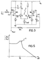
- the filter 1 comprises a resistor R between an input terminal Vin and an output terminal Vout. Also provided therein is an amplifier 5 connected after the resistor R and having an output B fed back to the input A through a capacitor C.
- This amplifier 5 is implemented by a transistor T1 of the n-channel MOS type which has a gate terminal G1 constituting the input A.
- This transistor T1 has its source S1 connected to ground via a resistor R1, and its drain D1 also connected to ground via a second transistor R2.
- the drain D1 is the output node B, and is also connected to a voltage supply Vo through a bias current generator Ip.
- the amplification gain k of the filter 1 is made intentionally small and lower than 10.
- This gain is nearly equal to the ratio of resistors R2 and R1, if the transconductance value gm of the MOS transistor T1 is taken high relatively to such resistors. That is, the product gm*R1 should be much larger than unity.
- the above-described circuit is characterized by low noise in the telephone band in which integrated speech circuits are usually required to operate.
- the filter pole that separates the DC reference signal from the AC signal is on the order of a few Hertz, not to affect the synthesis by the impedance associated with the integrated telephone circuit and the telephone band transmission gain.
- the circuit of this invention is operated within that band in a fully equivalent manner to a low-pass filter comprising a resistor R and a capacitor having a value of ( ⁇ k ⁇ +1)*C. It appears then as if the capacitance had been multiplied and the noise proportionally reduced.
- the input signal Vin is applied to the inverting (-) input of an operational amplifier A1 through a resistor R.
- the inverting input is also connected to a pole from which the supply voltage Vo is tapped.
- This amplifier A1 is selected to have a high DC gain, preferably of 100.
- the amplifier A1 has an output U fed back to the inverting (-) input through a capacitor C.
- the other, non-inverting (+) input of the amplifier A1 is connected, on the one side, to the inverting (-) input via a resistor R1, and on the other side, to ground via a capacitor C1.
- the amplifier A1 is implemented in the bipolar/MOS mixed technique with a differential cell 2 which includes common emitter transistors T3 and T4.
- the reference current Iref may be selected to provide a desired DC value at the output U.
- the inverting (-) and non-inverting (+) inputs of this differential cell are formed each of a corresponding one of n-channel MOS transistors M3 and M4, having respective sources S3 and S4 connected to the base terminals B3, B4 of their corresponding bipolar transistors in said cell 2.
- MOS transistors avoid the appearance of base current because they can be seen as infinite impedance inputs.
- the resistor R1 locates between the gate terminals G3, G4 of this MOS transistor pair, M3 and M4.
- circuit 3 comprising a switched capacitor type of filter. This circuit 3 would be effective to change a capacitance Cj into an equivalent resistance.
- Said circuit 3 comprises a pair of MOS transistors Mc1 nad Mc2 connected together and across the inputs of amplifier A1. Between these transistors and ground, a capacitor Cj is also connected.
- the equivalent resistance of Cj is given as 1/(cj*fc), and can be made quite large. This allows a much higher resistance for R1 than R, and as a result, a time constant R1*C1 which is much higher than the time constant R*C, even for the same capacitor values.
- the dominant pole of the circuit in Figure 2 locates approximately at 1/[R*C*(G+1)], and lies below the frequency range of said input signal.
- the low-pass filter formed of the resistor R1 and the capacitor C1 causes the DC signal between the two inputs of amplifier A1 to be null and, accordingly, not amplified.
- This variation of the filter 1 according to the invention is specially useful with telephone speech circuits because, despite the presence of a pole at frequencies on the order of some Hertz, it allows steady-state conditions to be attained in about a hundred milliseconds time after turning on the circuit.
- the filter of this invention unexpectedly shows to produce a speeding-up condition automatically in that, during the transition, the telephone circuit operates at a time constant which is set by the poles of the filter 1, which poles are not multiplied, however, by Miller Effect.
- the frequency response of the filter 1 is that shown in Figure 5, wherein a peak 4 of about 10 dB is outstanding proximate the value of 1/(20*R*C).
- the input signal Vin would not be sampled, thereby making the provision of an antialias and/or smoothing filter unnecessary.
- the filter of this invention solves, in its various embodiments, the technical problem and affords a number of advantages, outstanding among which is the fact that, for the same area of the integrated circuit, a much higher time constant ⁇ G ⁇ +1 can be achieved.
Landscapes
- Networks Using Active Elements (AREA)
- Amplifiers (AREA)
- Filters And Equalizers (AREA)
Priority Applications (4)
| Application Number | Priority Date | Filing Date | Title |
|---|---|---|---|
| EP92830422A EP0580922B1 (de) | 1992-07-29 | 1992-07-29 | RC-Filter für niedrige und sehr niedrige Frequenzanwendungen |
| DE69223318T DE69223318T2 (de) | 1992-07-29 | 1992-07-29 | RC-Filter für niedrige und sehr niedrige Frequenzanwendungen |
| US08/097,067 US5434535A (en) | 1992-07-29 | 1993-07-23 | RC filter for low and very low frequency applications |
| JP5188232A JPH06224689A (ja) | 1992-07-29 | 1993-07-29 | 低周波及び超低周波応用装置のためのrcフィルタ |
Applications Claiming Priority (1)
| Application Number | Priority Date | Filing Date | Title |
|---|---|---|---|
| EP92830422A EP0580922B1 (de) | 1992-07-29 | 1992-07-29 | RC-Filter für niedrige und sehr niedrige Frequenzanwendungen |
Publications (2)
| Publication Number | Publication Date |
|---|---|
| EP0580922A1 true EP0580922A1 (de) | 1994-02-02 |
| EP0580922B1 EP0580922B1 (de) | 1997-11-26 |
Family
ID=8212149
Family Applications (1)
| Application Number | Title | Priority Date | Filing Date |
|---|---|---|---|
| EP92830422A Expired - Lifetime EP0580922B1 (de) | 1992-07-29 | 1992-07-29 | RC-Filter für niedrige und sehr niedrige Frequenzanwendungen |
Country Status (4)
| Country | Link |
|---|---|
| US (1) | US5434535A (de) |
| EP (1) | EP0580922B1 (de) |
| JP (1) | JPH06224689A (de) |
| DE (1) | DE69223318T2 (de) |
Cited By (2)
| Publication number | Priority date | Publication date | Assignee | Title |
|---|---|---|---|---|
| EP0907250A3 (de) * | 1997-09-25 | 1999-10-27 | Motorola Ltd | Integriertes analoges Tiefpassfilter |
| EP0818885A3 (de) * | 1996-07-12 | 2000-01-05 | Siemens Aktiengesellschaft | Filterschaltung |
Families Citing this family (11)
| Publication number | Priority date | Publication date | Assignee | Title |
|---|---|---|---|---|
| JP3638075B2 (ja) * | 1997-07-29 | 2005-04-13 | 富士通株式会社 | 回路 |
| US5952877A (en) * | 1997-11-21 | 1999-09-14 | International Business Machines Corporation | Integrated resistor for continuous time signal processing applications |
| JP2005535954A (ja) * | 2002-08-08 | 2005-11-24 | コーニンクレッカ フィリップス エレクトロニクス エヌ ヴィ | 電圧調整器 |
| JP4730153B2 (ja) * | 2006-03-15 | 2011-07-20 | 株式会社デンソー | フィルタ回路 |
| US7567133B2 (en) * | 2006-04-06 | 2009-07-28 | Mosaid Technologies Corporation | Phase-locked loop filter capacitance with a drag current |
| US7692460B2 (en) * | 2007-10-24 | 2010-04-06 | International Business Machines Corporation | Structure for precision integrated phase lock loop circuit loop filter |
| US7701269B2 (en) * | 2007-10-24 | 2010-04-20 | International Business Machines Corporation | Method and system for managing voltage swings across field effect transistors |
| US8201112B2 (en) * | 2007-10-24 | 2012-06-12 | International Business Machines Corporation | Structure for managing voltage swings across field effect transistors |
| US20140035666A1 (en) * | 2009-08-13 | 2014-02-06 | Rafaela Volpe | Op-R, A Solid State Filter |
| CN110311650B (zh) * | 2019-06-26 | 2023-05-02 | 湖南国科微电子股份有限公司 | 低通滤波电路、低通滤波器以及cmos芯片 |
| CN111654263B (zh) * | 2020-05-12 | 2023-05-16 | 成都华微电子科技股份有限公司 | 带有低通滤波器的集成电路 |
Citations (2)
| Publication number | Priority date | Publication date | Assignee | Title |
|---|---|---|---|---|
| FR2253313A1 (de) * | 1973-11-30 | 1975-06-27 | Ird Mechanalysis | |
| EP0274784A1 (de) * | 1986-12-11 | 1988-07-20 | Koninklijke Philips Electronics N.V. | Filteranordnung |
Family Cites Families (12)
| Publication number | Priority date | Publication date | Assignee | Title |
|---|---|---|---|---|
| US3805178A (en) * | 1972-08-25 | 1974-04-16 | Post Office | Rc active filter circuit |
| US3786363A (en) * | 1973-01-05 | 1974-01-15 | Us Navy | Voltage-controlled low-pass filter |
| US4112382A (en) * | 1973-11-30 | 1978-09-05 | Ird Mechanalysis, Inc. | Digital sweep circuit for generating sawtooth wave form |
| US4035733A (en) * | 1973-11-30 | 1977-07-12 | Ird Mechanalysis, Inc. | Pulse signal conditioning circuit |
| US4044310A (en) * | 1973-11-30 | 1977-08-23 | Ird Mechanalysis, Inc. | Circuitry for generating a sine wave and/or cosine wave from a pulse signal |
| JPS6133709Y2 (de) * | 1977-11-24 | 1986-10-02 | ||
| US4783635A (en) * | 1986-09-22 | 1988-11-08 | Linear Technology Corporation | Low pass filter circuit |
| US4767998A (en) * | 1987-02-19 | 1988-08-30 | The United States Of America As Represented By The Secretary Of The Navy | Active filter using low gain amplification stages |
| JP2598412B2 (ja) * | 1987-07-10 | 1997-04-09 | 株式会社日立製作所 | 半導体記憶装置 |
| US5089789A (en) * | 1990-05-16 | 1992-02-18 | Texas Instruments Incorporated | Differential amplifier |
| IT1241345B (it) * | 1990-12-11 | 1994-01-10 | Sgs Thomson Microelectronics | Circuito per la soppressione del rumore di commutazione fra due sorgenti di tensione, in paticolare per stadi audio di preamplificazione |
| US5168180A (en) * | 1992-04-20 | 1992-12-01 | Motorola, Inc. | Low frequency filter in a monolithic integrated circuit |
-
1992
- 1992-07-29 EP EP92830422A patent/EP0580922B1/de not_active Expired - Lifetime
- 1992-07-29 DE DE69223318T patent/DE69223318T2/de not_active Expired - Fee Related
-
1993
- 1993-07-23 US US08/097,067 patent/US5434535A/en not_active Expired - Fee Related
- 1993-07-29 JP JP5188232A patent/JPH06224689A/ja active Pending
Patent Citations (2)
| Publication number | Priority date | Publication date | Assignee | Title |
|---|---|---|---|---|
| FR2253313A1 (de) * | 1973-11-30 | 1975-06-27 | Ird Mechanalysis | |
| EP0274784A1 (de) * | 1986-12-11 | 1988-07-20 | Koninklijke Philips Electronics N.V. | Filteranordnung |
Cited By (2)
| Publication number | Priority date | Publication date | Assignee | Title |
|---|---|---|---|---|
| EP0818885A3 (de) * | 1996-07-12 | 2000-01-05 | Siemens Aktiengesellschaft | Filterschaltung |
| EP0907250A3 (de) * | 1997-09-25 | 1999-10-27 | Motorola Ltd | Integriertes analoges Tiefpassfilter |
Also Published As
| Publication number | Publication date |
|---|---|
| US5434535A (en) | 1995-07-18 |
| EP0580922B1 (de) | 1997-11-26 |
| DE69223318D1 (de) | 1998-01-08 |
| JPH06224689A (ja) | 1994-08-12 |
| DE69223318T2 (de) | 1998-03-19 |
Similar Documents
| Publication | Publication Date | Title |
|---|---|---|
| US4723110A (en) | Transconductance amplifier | |
| US4374335A (en) | Tuneable I.C. active integrator | |
| DE69207612T2 (de) | Frequenzkompensierter Mehrstufenverstärker mit verschachtelter kapazitiver Neutralisierung und innerer Mehrweg-Vorwärtssteuerung | |
| EP0580922B1 (de) | RC-Filter für niedrige und sehr niedrige Frequenzanwendungen | |
| US8254598B2 (en) | Programmable integrated microphone interface circuit | |
| US8335328B2 (en) | Programmable integrated microphone interface circuit | |
| JP3316038B2 (ja) | 演算トランスコンダクタンス増幅器・キャパシタ対用の周波数同調システム | |
| US5049831A (en) | Single-ended input to differential output amplifier with integral two-pole filter | |
| US4586000A (en) | Transformerless current balanced amplifier | |
| EP0579875B1 (de) | System zur Abstimmung eines Qualitätsfaktors | |
| KR0151397B1 (ko) | 집적 회로화된 필터 및 필터셀 | |
| CN1049540C (zh) | 用作同步视频检波器的受控振荡器 | |
| EP0730345B1 (de) | Schaltung mit variabler Verstärkung | |
| EP0365091A2 (de) | Filterschaltungsanordnung | |
| KR0171652B1 (ko) | 자기 바이어스용 네거티브 피드백 루프를 갖는 증폭기 회로 | |
| JPH06177671A (ja) | 同相モード信号センサ | |
| EP1811662B1 (de) | Biquadratisches Tiefpassfilter mit variabler Verstärkung | |
| Satansup et al. | High-Input-Impedance Four-Input Single-Output Voltage-Mode Biquadratic Filter with Only VDTAs and Grounded Capacitors | |
| EP1629594A1 (de) | Verbesserungen an oder bezüglich transkonduktanzschaltungen | |
| JPS63244922A (ja) | キヤパシタンス回路 | |
| JPH01316014A (ja) | アクティブフィルター回路 | |
| JPH0453065Y2 (de) | ||
| KR0172421B1 (ko) | 대역통과 필터 장치 | |
| JP3041871B2 (ja) | 信号補正回路 | |
| JP3113147B2 (ja) | フィルタ装置 |
Legal Events
| Date | Code | Title | Description |
|---|---|---|---|
| PUAI | Public reference made under article 153(3) epc to a published international application that has entered the european phase |
Free format text: ORIGINAL CODE: 0009012 |
|
| AK | Designated contracting states |
Kind code of ref document: A1 Designated state(s): DE FR GB IT |
|
| 17P | Request for examination filed |
Effective date: 19940528 |
|
| 17Q | First examination report despatched |
Effective date: 19960722 |
|
| GRAG | Despatch of communication of intention to grant |
Free format text: ORIGINAL CODE: EPIDOS AGRA |
|
| GRAH | Despatch of communication of intention to grant a patent |
Free format text: ORIGINAL CODE: EPIDOS IGRA |
|
| GRAH | Despatch of communication of intention to grant a patent |
Free format text: ORIGINAL CODE: EPIDOS IGRA |
|
| GRAA | (expected) grant |
Free format text: ORIGINAL CODE: 0009210 |
|
| AK | Designated contracting states |
Kind code of ref document: B1 Designated state(s): DE FR GB IT |
|
| ET | Fr: translation filed | ||
| REF | Corresponds to: |
Ref document number: 69223318 Country of ref document: DE Date of ref document: 19980108 |
|
| RAP4 | Party data changed (patent owner data changed or rights of a patent transferred) |
Owner name: STMICROELECTRONICS S.R.L. |
|
| PLBE | No opposition filed within time limit |
Free format text: ORIGINAL CODE: 0009261 |
|
| 26N | No opposition filed | ||
| REG | Reference to a national code |
Ref country code: GB Ref legal event code: IF02 |
|
| PGFP | Annual fee paid to national office [announced via postgrant information from national office to epo] |
Ref country code: DE Payment date: 20020807 Year of fee payment: 11 |
|
| PG25 | Lapsed in a contracting state [announced via postgrant information from national office to epo] |
Ref country code: DE Free format text: LAPSE BECAUSE OF NON-PAYMENT OF DUE FEES Effective date: 20040203 |
|
| PGFP | Annual fee paid to national office [announced via postgrant information from national office to epo] |
Ref country code: FR Payment date: 20040708 Year of fee payment: 13 |
|
| PGFP | Annual fee paid to national office [announced via postgrant information from national office to epo] |
Ref country code: GB Payment date: 20040728 Year of fee payment: 13 |
|
| PG25 | Lapsed in a contracting state [announced via postgrant information from national office to epo] |
Ref country code: IT Free format text: LAPSE BECAUSE OF NON-PAYMENT OF DUE FEES;WARNING: LAPSES OF ITALIAN PATENTS WITH EFFECTIVE DATE BEFORE 2007 MAY HAVE OCCURRED AT ANY TIME BEFORE 2007. THE CORRECT EFFECTIVE DATE MAY BE DIFFERENT FROM THE ONE RECORDED. Effective date: 20050729 Ref country code: GB Free format text: LAPSE BECAUSE OF NON-PAYMENT OF DUE FEES Effective date: 20050729 |
|
| GBPC | Gb: european patent ceased through non-payment of renewal fee |
Effective date: 20050729 |
|
| PG25 | Lapsed in a contracting state [announced via postgrant information from national office to epo] |
Ref country code: FR Free format text: LAPSE BECAUSE OF NON-PAYMENT OF DUE FEES Effective date: 20060331 |
|
| REG | Reference to a national code |
Ref country code: FR Ref legal event code: ST Effective date: 20060331 |