EP0581018A1 - Blanchet avec amortissement du bruit - Google Patents
Blanchet avec amortissement du bruit Download PDFInfo
- Publication number
- EP0581018A1 EP0581018A1 EP93110104A EP93110104A EP0581018A1 EP 0581018 A1 EP0581018 A1 EP 0581018A1 EP 93110104 A EP93110104 A EP 93110104A EP 93110104 A EP93110104 A EP 93110104A EP 0581018 A1 EP0581018 A1 EP 0581018A1
- Authority
- EP
- European Patent Office
- Prior art keywords
- cylindrical body
- blanket
- blanket cylinder
- sleeve
- compressed air
- Prior art date
- Legal status (The legal status is an assumption and is not a legal conclusion. Google has not performed a legal analysis and makes no representation as to the accuracy of the status listed.)
- Granted
Links
- 238000013016 damping Methods 0.000 claims abstract description 38
- 238000007645 offset printing Methods 0.000 claims abstract description 7
- 238000007639 printing Methods 0.000 claims description 36
- 239000010410 layer Substances 0.000 description 22
- 239000000463 material Substances 0.000 description 15
- 230000003014 reinforcing effect Effects 0.000 description 6
- PXHVJJICTQNCMI-UHFFFAOYSA-N Nickel Chemical compound [Ni] PXHVJJICTQNCMI-UHFFFAOYSA-N 0.000 description 4
- 239000004005 microsphere Substances 0.000 description 3
- 239000004744 fabric Substances 0.000 description 2
- 238000000034 method Methods 0.000 description 2
- 229910052759 nickel Inorganic materials 0.000 description 2
- 239000011358 absorbing material Substances 0.000 description 1
- 239000000853 adhesive Substances 0.000 description 1
- 238000004026 adhesive bonding Methods 0.000 description 1
- 230000001070 adhesive effect Effects 0.000 description 1
- 239000012790 adhesive layer Substances 0.000 description 1
- 238000007664 blowing Methods 0.000 description 1
- 238000002386 leaching Methods 0.000 description 1
- 239000002184 metal Substances 0.000 description 1
- 229910052751 metal Inorganic materials 0.000 description 1
- 238000012986 modification Methods 0.000 description 1
- 230000004048 modification Effects 0.000 description 1
- 239000003973 paint Substances 0.000 description 1
- 229920002959 polymer blend Polymers 0.000 description 1
- 238000004804 winding Methods 0.000 description 1
Images

Classifications
-
- B—PERFORMING OPERATIONS; TRANSPORTING
- B41—PRINTING; LINING MACHINES; TYPEWRITERS; STAMPS
- B41F—PRINTING MACHINES OR PRESSES
- B41F13/00—Common details of rotary presses or machines
- B41F13/08—Cylinders
- B41F13/193—Transfer cylinders; Offset cylinders
-
- B—PERFORMING OPERATIONS; TRANSPORTING
- B41—PRINTING; LINING MACHINES; TYPEWRITERS; STAMPS
- B41N—PRINTING PLATES OR FOILS; MATERIALS FOR SURFACES USED IN PRINTING MACHINES FOR PRINTING, INKING, DAMPING, OR THE LIKE; PREPARING SUCH SURFACES FOR USE AND CONSERVING THEM
- B41N10/00—Blankets or like coverings; Coverings for wipers for intaglio printing
- B41N10/02—Blanket structure
-
- B—PERFORMING OPERATIONS; TRANSPORTING
- B41—PRINTING; LINING MACHINES; TYPEWRITERS; STAMPS
- B41N—PRINTING PLATES OR FOILS; MATERIALS FOR SURFACES USED IN PRINTING MACHINES FOR PRINTING, INKING, DAMPING, OR THE LIKE; PREPARING SUCH SURFACES FOR USE AND CONSERVING THEM
- B41N6/00—Mounting boards; Sleeves Make-ready devices, e.g. underlays, overlays; Attaching by chemical means, e.g. vulcanising
Definitions
- the present invention relates to an offset printing unit, in particular a printing blanket for a blanket cylinder in the printing unit.
- An offset printing unit has a number of rotatable cylinders, including a plate cylinder and a blanket cylinder.
- the plate cylinder carries a printing plate, on the surface of which a colored print image is fixed.
- the blanket cylinder carries a blanket. When the cylinder rotates, the plate on the plate cylinder transfers the ink image printed onto the blanket on the blanket cylinder in the gap between the plate cylinder and the blanket cylinder. The rubber blanket on the blanket cylinder then transfers the inked print image onto the material to be printed, such as a paper web.
- a conventional blanket is in the form of a sheet or sheet and is applied to a blanket cylinder by being wound around it.
- a rubber blanket can alternatively also be designed as a sleeve and attached to a blanket cylinder by telescopic sliding.
- Such a sleeve-like rubber blanket has a cylindrical body which supports the rubber blanket in its sleeve-like shape.
- the cylindrical body and the blanket cylinder are designed so that the cylindrical body can be attached with a tight fit over the blanket cylinder.
- the blanket cylinder is provided with air flow openings through which compressed air flows over the blanket cylinder. If the cylindrical body in the sleeve-shaped rubber blanket is located above the air flow openings in the rubber blanket cylinder, it becomes diametrical due to the compressed air flow stretched. In its stretched state, the cylindrical body can be pushed axially onto and from the blanket cylinder. When the compressed air is reduced, the cylindrical body contracts over the blanket cylinder and thus creates a tight fit on the blanket cylinder.
- a printing blanket for an offset printing unit has a sleeve-like shape and can be mounted telescopically over a blanket cylinder which is provided with air flow openings through which compressed air flows over the blanket cylinder.
- the sleeve-shaped rubber blanket has a cylindrical pressure part with a cylindrical outer pressure surface.
- the sleeve-shaped rubber blanket also has a cylindrical body which carries the cylindrical pressure part.
- the cylindrical body can be in an original state and in a stretched state. In its original state, the cylindrical body has an inside diameter that is smaller than the diameter of the blanket cylinder. In its stretched state, it has an inside diameter that is larger than the diameter of the blanket cylinder.
- the cylindrical body in the sleeve-shaped rubber blanket can be brought into its stretched state under the influence of a compressed air flow over the rubber blanket cylinder when it is placed telescopically over the air flow openings in the rubber blanket cylinder.
- the sleeve-shaped rubber blanket further comprises a device for damping noise which is caused by the compressed air flow acting on the sleeve-shaped rubber blanket.
- the noise damping device dampens the vibration of the cylindrical body of the sleeve-shaped rubber blanket caused by the acting compressed air flow.
- the cylindrical body has an end piece which extends axially beyond the end of the blanket cylinder, and the noise damping device consists of a damping ring which extends circumferentially around the inside of the end piece of the body.
- the damping ring is a thin strip of noise-absorbing material that permanently adheres to the inner surface of the cylindrical body.
- a printing unit 10 constructed according to the present invention is shown schematically in FIG. 1.
- the printing unit 10 as an example, is an offset printing unit for lithographic printing with a plate cylinder 12, a blanket cylinder 14 and a printing cylinder 15.
- the plate cylinder 12, the Blanket cylinders 14 and impression cylinders 15 are rotatably supported with their respective ends in a pair of side frames 16, one of which is shown in FIG. 1.
- the plate cylinder 12 carries a printing plate 18 on which an image to be printed is fixed.
- the pressure plate 18 is made of thin metal and is attached to the plate cylinder 12 by winding it around the plate cylinder 12.
- a clamping mechanism 19 in the plate cylinder 12 holds the printing plate 18 thereon.
- the blanket cylinder 14 carries a blanket 20.
- the blanket is designed as a sleeve which is attached to the blanket cylinder 14 by telescopic sliding.
- the printing unit 10 also includes inking rollers 22, an ink fountain 24 and a motor 26.
- the motor 26 drives a gear train (not shown) which is connected to the cylinders and rollers in the printing unit 10 and which are shown by the arrow in Fig. 1 indicated direction rotates.
- the engine 26 and the gear train can be constructed in the manner known in the art.
- the inking rollers 22 transfer ink from the ink fountain 24 to the printing plate 18 on the plate cylinder 12.
- the printing plate 18 transfers the colored printing image the blanket 20 on the blanket cylinder 14.
- the blanket then transfers the inked print image to the material to be printed, which is preferably a web moving through the gap 32 between the blanket cylinder 14 and the impression cylinder 15.
- the impression cylinder 15 is a second blanket cylinder with a second sleeve-shaped blanket 34 for simultaneous printing on the opposite side of the web 30.
- the blanket 20 has a pressure member 40 and a supporting cylindrical body 42.
- the pressure member 40 is elastic and has a cylindrical shape with a gapless cylindrical outer pressure surface 44.
- the cylindrical body 42 is relatively rigid and has a gapless cylindrical inner surface 46 which extends circumferentially completely around the outer surface 48 of the blanket cylinder 14.
- cylindrical body 42 is made of nickel.
- the pressure member 40 of the blanket 20 is made of layers.
- the pressure member 40 is composed of layers similar to those shown in U.S. Pat. Patent No. 3,700,541 -shrimpton et al - disclosed layers of a rubber blanket. Accordingly, the pressure member 40 has a compressible layer 50, a reinforcing layer 52 and a pressure layer 54.
- the compressible layer 50 in the pressure part 40 of the rubber blanket 20 is fastened by gluing to the cylindrical rubber blanket body 42 and represents a body 62 made of rubber-like material.
- the body 62 made of rubber-like material has evenly distributed microcells 64 which give the body 62 the compressibility.
- the microcells are created by incorporating compressible, hollow microspheres 66 into the rubber-like material of the body 62.
- the body 62 of the rubber-like material could also be produced by adding a material other than microspheres 66, e.g. B. can be made compressible by known from the US Patent No. 3,887,750 - Duckett et al - compressible pieces of thread.
- the body 62 could be made compressible by known methods of creating voids, such as blowing and leaching, known from US Patent No. 4,025,685 to Haran et al.
- the reinforcing layer 52 in the pressure part 40 of the rubber blanket 20 consists of a fabric 70 connected with a polymer mixture.
- the pressure layer 54 consists of a body 72 made of rubber-like material and forms the outer pressure surface 44 of the rubber blanket 20. Unlike that in the Shrimpton et al
- the printing layer shown in the patent is cylindrical, the printing layer 54 of this invention, and the outer printing surface 44 is a continuous, gapless cylindrical surface extending all the way around the blanket 20.
- the printing plate 18 on the plate cylinder 12 moves against the blanket 20 on the blanket cylinder 14.
- the rubber blanket is pressed in, where the pressure plate 18 presses against it in the cylinder gap 28.
- the compressible layer 50 in the rubber blanket 20 is compressed below the pressed-in part of the printing layer 54 and the reinforcing layer 52.
- the compressible layer 50 thus allows the pressure layer 54 and the reinforcing layer 52 to be displaced radially inwards, so that the pressure surface 44 on the pressure layer 54 on both sides of the cylinder gap 28 does not bulge radially outwards.
- the rubber blanket 20 has a central axis 90.
- the blanket cylinder 14 has a central axis 100 and a pair of journal shafts 102 on which it is supported and rotates about its central axis 100 in the printing unit 10.
- the blanket cylinder 14 also has a beveled edge surface 106 at an axial end of its jacket surface 48.
- the jacket surface of the blanket cylinder 14 has a diameter which is slightly larger than the inside diameter of the cylindrical body 42 of the blanket 20.
- the beveled edge surface 106 of the blanket cylinder 14 is inclined radially inward from the lateral surface 48 and has a diameter at its radial inner end which is slightly smaller than the inner diameter of the cylindrical body 42.
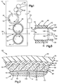
- the blanket cylinder 14 has a number of air flow openings 108 on its outer surface 48.
- the air flow openings 108 are arranged circumferentially in a row at a small distance from the chamfered edge surface 106 and are through a number of air openings 112 (FIGS. 2, 3) within the rubber blanket cylinder 14 connected to an air inlet 110.
- the air inlet 110 is optionally connected to a compressed air source 114 by a compressed air line 116.
- the rubber blanket can be telescopically pushed over the rubber blanket cylinder. Since the outer surface 48 of the blanket cylinder 14 has a diameter that is slightly larger than the inner diameter of the cylindrical body 42 in the blanket 20, the cylindrical body 42 is forced to expand diametrically when it is against the beveled edge surface 106 and axially moved to the outer surface 48. If the cylindrical body 42 is moved with its inner surface 46 axially via the air flow openings 108 on the outer surface 48 of the blanket cylinder 14, one of them Source 114 compressed air directed at the air flow openings 108. The compressed air flows radially out of the openings 108 and strikes the inner surface 46 of the cylindrical body 42 so that it expands diametrically.
- the compressed air directed against the inner surface 46 of the cylindrical body 42 continuously expands the cylindrical body 42 while it is being moved axially over the outer surface 48 of the blanket cylinder 14.
- the air pressure is switched off.
- the cylindrical body 42 then contracts diametrically around the outer surface of the blanket cylinder 14 in an elastic manner.
- the blanket 20 which has an original inner diameter that is smaller than the diameter of the outer surface 48 of the blanket cylinder 14, is installed with a tight fit on the blanket cylinder 14.
- the blanket 20 is then removed from the blanket cylinder 14 by stretching the cylindrical body 42 again under the influence of compressed air and in this state the blanket 20 is axially pushed down from the blanket cylinder 14.
- the nickel material of the cylindrical body 42 has the optimal elasticity for installing and removing the blanket in the manner described above when subjected to pressure from a conventional pneumatic source of 6.2 bar.
- the blanket 20 in the preferred embodiment has a noise damping member in the form of a vibration damping ring 120.
- the damping ring 120 is mounted on the inner surface 46 of the cylindrical body 42 and dampens the vibration thereof , which is caused by the flow of compressed air between the outer surface 48 and the inner surface 46.
- the damping ring 120 significantly reduces the level of noise that must be tolerated by personnel working with the printing unit 10.
- the cylindrical body 42 has an end portion 122 that is outside the end of the blanket cylinder 14 when the blanket 20 is installed on the blanket cylinder 14, as shown in FIG. 5.
- the damping ring 120 is fixed on the inner surface 46 on the outer edge 124 of the end part 122.
- the damping ring 120 then makes it easier to handle the cylindrical body 42 at the edge 124.
- the damping ring 120 is held in its position on the inner surface 46 of the cylindrical body 42 by the centrifugal force acting thereon, which arises when the rubber blanket 20 rotates with the rubber blanket cylinder 14.
- the damping ring 120 could also be attached to the outer surface of the cylindrical body 42, as shown in broken lines in FIG.
- damping ring 120 would then have to be attached more firmly to the cylindrical body 42.
- damping rings or other noise damping elements can also be used as required, for which the material, the dimension and the location of the attachment must be selected accordingly. It could e.g. B. the other end of the blanket 20 may be formed as shown in Fig. 5, and one or a plurality of damping rings are attached to the outer surface of the respective end part of the cylindrical body 42.
- the damping ring 120 preferably consists of a resilient strip of a resin-like and / or other damping material with a length that corresponds to the circumference of the inner surface 46 of the cylindrical body 42 and is permanently glued to the inner surface 46 with an adhesive.
- damping stanchion 120 is such a strip of noise damping material with an adhesive layer; this material is distributed by Sound Seal, a subsidiary of United Process, Inc., under the trademark "ANTIPHON LD-13".
Landscapes
- Engineering & Computer Science (AREA)
- Mechanical Engineering (AREA)
- Printing Plates And Materials Therefor (AREA)
- Supply, Installation And Extraction Of Printed Sheets Or Plates (AREA)
Applications Claiming Priority (2)
| Application Number | Priority Date | Filing Date | Title |
|---|---|---|---|
| US07/909,730 US5215013A (en) | 1992-07-07 | 1992-07-07 | Printing blanket with noise attenuation |
| US909730 | 1992-07-07 |
Publications (2)
| Publication Number | Publication Date |
|---|---|
| EP0581018A1 true EP0581018A1 (fr) | 1994-02-02 |
| EP0581018B1 EP0581018B1 (fr) | 1997-01-08 |
Family
ID=25427734
Family Applications (1)
| Application Number | Title | Priority Date | Filing Date |
|---|---|---|---|
| EP93110104A Expired - Lifetime EP0581018B1 (fr) | 1992-07-07 | 1993-06-24 | Blanchet avec amortissement du bruit |
Country Status (4)
| Country | Link |
|---|---|
| US (1) | US5215013A (fr) |
| EP (1) | EP0581018B1 (fr) |
| JP (1) | JP3329890B2 (fr) |
| DE (2) | DE4320924C2 (fr) |
Families Citing this family (35)
| Publication number | Priority date | Publication date | Assignee | Title |
|---|---|---|---|---|
| DE4340915A1 (de) * | 1993-02-23 | 1994-08-25 | Heidelberger Druckmasch Ag | Auswechselbare Andrückhülse |
| US5347927A (en) * | 1993-05-04 | 1994-09-20 | W. R. Grace & Co.-Conn. | Anisotropic endless printing element and method for making the same |
| EP0652104B1 (fr) * | 1993-11-05 | 2002-04-10 | MAN Roland Druckmaschinen AG | Unité d'impression pour impression offset sans eau de mouillage |
| US6105498A (en) * | 1993-12-21 | 2000-08-22 | Heidelberger Druckmaschinen Ag | Varying profile cylinder blanket |
| DE4432816A1 (de) * | 1994-09-15 | 1996-03-21 | Roland Man Druckmasch | Druckwalze für den kanallosen Druck |
| US5813336A (en) * | 1995-12-22 | 1998-09-29 | Heidelberger Druckmaschinen Ag | Printing unit with axially removable printing sleeves |
| DE59706477D1 (de) * | 1996-07-16 | 2002-04-04 | Roland Man Druckmasch | Gummizylinderhülse, insbesondere für Offset-Rollenrotationsdruckmaschinen |
| JP3510452B2 (ja) * | 1997-05-13 | 2004-03-29 | 三菱重工業株式会社 | 印刷機,印刷ユニットおよび筒状ブランケットセット |
| CA2224762A1 (fr) * | 1998-01-23 | 1999-07-23 | Bob Erbstein | Unite a decoupage variable pour une presse |
| US5987748A (en) * | 1998-07-31 | 1999-11-23 | Monarch Marking Systems, Inc. | Method of making ink roller assembly |
| US5953992A (en) * | 1998-07-31 | 1999-09-21 | Monarch Marking Systems, Inc. | Method of making ink roller assembly |
| US6062138A (en) * | 1999-03-30 | 2000-05-16 | Howard A. Fromson | Offset printing having blanket cylinder with blanket having different thicknesses |
| FR2793725B1 (fr) | 1999-05-20 | 2001-07-27 | Polyfibron Technologies Sa | Cylindre d'impression comprenant des moyens d'indexage pour le montage d'un manchon d'impression sur le cylindre support |
| US6347586B1 (en) * | 2000-04-19 | 2002-02-19 | Heidelberger Druckmaschinen Ag | Method and device for reducing printing sleeve noise |
| DE10117409B4 (de) * | 2001-04-06 | 2011-06-01 | Contitech Elastomer-Beschichtungen Gmbh | Drucktuch zur Verwendung auf Druckzylindern für insbesondere Offset-Druckmaschinen |
| JP2001310571A (ja) * | 2000-04-20 | 2001-11-06 | Contitech Elastomer-Beschichtungen Gmbh | 特にオフセット印刷機用の圧胴に使用するブランケットとその製造方法 |
| DE50111987D1 (de) | 2000-05-17 | 2007-03-22 | Eastman Kodak Co | Austauschbare Zylinderelemente an elektrographischen Druckeinheiten |
| IT1318961B1 (it) | 2000-10-03 | 2003-09-19 | Erminio Rossini S P A Ora Ross | Manica perfezionata per cilindro sussidiario di una macchina da stampaindiretta o "offset". |
| US7107907B2 (en) | 2001-01-22 | 2006-09-19 | Goss International Americas, Inc. | Flow-restricted printing cylinder for a removable printing sleeve |
| DE10212943B4 (de) * | 2002-03-22 | 2010-05-27 | Eastman Kodak Co. | Zylinder für eine elektrofotografische Druckmaschine |
| US7010246B2 (en) * | 2002-06-10 | 2006-03-07 | Ricoh Company, Ltd. | Image forming apparatus, drum unit, image forming module, and method of insertion and removal of a damper into and from an image carrier drum |
| DE10228686A1 (de) * | 2002-06-27 | 2004-02-12 | Man Roland Druckmaschinen Ag | Gummizylinderhülse für Offset-Druckmaschinen |
| US20040238143A1 (en) * | 2002-12-12 | 2004-12-02 | Atsushi Kitamura | Sleeve for press roll and sleeve mounted press roll |
| GB2400860A (en) * | 2003-04-24 | 2004-10-27 | Gcc Man Ltd | Developer sleeve |
| US6732648B1 (en) | 2003-05-05 | 2004-05-11 | Day International Inc. | Printing blanket sleeve having sound dampening feature |
| DE602004020612D1 (de) * | 2003-06-09 | 2009-05-28 | Goss Internat Inc | Offsetdruckmaschine mit freitragenden druck- und einfärbemodulen |
| US6938548B1 (en) | 2004-04-30 | 2005-09-06 | Eastman Kodak Company | Printing sleeve noise reducer |
| DE102004048634A1 (de) * | 2004-10-06 | 2006-04-20 | Man Roland Druckmaschinen Ag | Hülse, insbesondere Distanzhülse |
| US20070203433A1 (en) * | 2006-02-27 | 2007-08-30 | Murphy Martin P | Relaxation inducing apparatus |
| US20090193991A1 (en) * | 2008-02-04 | 2009-08-06 | Felice Rossini | Blanket sleeve and cylinder and method of making same |
| US20100307356A1 (en) * | 2008-02-04 | 2010-12-09 | Felice Rossini | Bridged sleeve/cylinder and method of making same for web offset printing machines |
| DE102009001822A1 (de) * | 2008-12-18 | 2010-07-01 | Manroland Ag | Radial dehnbares, hülsenförmiges Drucktuch und Verfahren zur Herstellung eines solchen Drucktuches |
| JP2011136580A (ja) * | 2011-03-07 | 2011-07-14 | Universal Seikan Kk | 缶の印刷装置及びスリーブ |
| JP5485206B2 (ja) * | 2011-03-07 | 2014-05-07 | ユニバーサル製缶株式会社 | 缶の印刷装置及びスリーブ |
| DE102011106886A1 (de) * | 2011-07-07 | 2013-01-10 | Manroland Web Systems Gmbh | Druckwerkszylinder und hülsenförmiger Zylinderaufzug für einen Druckwerkszylinder |
Citations (2)
| Publication number | Priority date | Publication date | Assignee | Title |
|---|---|---|---|---|
| EP0225509A2 (fr) * | 1985-12-11 | 1987-06-16 | Tittgemeyer Engineering Gmbh | Dispositif pour imprimer une bande |
| EP0421145A2 (fr) * | 1989-10-05 | 1991-04-10 | Heidelberger Druckmaschinen Aktiengesellschaft | Machine d'impression lithographique |
Family Cites Families (7)
| Publication number | Priority date | Publication date | Assignee | Title |
|---|---|---|---|---|
| US650290A (en) * | 1900-02-17 | 1900-05-22 | Matthias J Wirt | Device for deadening noise. |
| US3700541A (en) * | 1970-04-11 | 1972-10-24 | Dunlop Holdings Ltd | Printers' blankets |
| US3887750A (en) * | 1973-01-08 | 1975-06-03 | Dayco Corp | Compressible printing blanket |
| US4025685A (en) * | 1974-09-06 | 1977-05-24 | Dayco Corporation | Compressible printing blanket and method of manufacture |
| JPS5163708A (fr) * | 1974-09-26 | 1976-06-02 | Emu Ei Batsukuree Engureibingu | |
| DE3624430A1 (de) * | 1986-07-18 | 1988-02-04 | Westerwaelder Eisen Gerhard | Tankanordnung |
| DE4217793C1 (de) * | 1992-05-29 | 1993-12-09 | Roland Man Druckmasch | Offset-Gummituch und Verfahren zu dessen Herstellung |
-
1992
- 1992-07-07 US US07/909,730 patent/US5215013A/en not_active Expired - Lifetime
-
1993
- 1993-06-24 DE DE4320924A patent/DE4320924C2/de not_active Expired - Fee Related
- 1993-06-24 DE DE59305032T patent/DE59305032D1/de not_active Expired - Lifetime
- 1993-06-24 EP EP93110104A patent/EP0581018B1/fr not_active Expired - Lifetime
- 1993-07-06 JP JP16675293A patent/JP3329890B2/ja not_active Expired - Fee Related
Patent Citations (2)
| Publication number | Priority date | Publication date | Assignee | Title |
|---|---|---|---|---|
| EP0225509A2 (fr) * | 1985-12-11 | 1987-06-16 | Tittgemeyer Engineering Gmbh | Dispositif pour imprimer une bande |
| EP0421145A2 (fr) * | 1989-10-05 | 1991-04-10 | Heidelberger Druckmaschinen Aktiengesellschaft | Machine d'impression lithographique |
Also Published As
| Publication number | Publication date |
|---|---|
| JP3329890B2 (ja) | 2002-09-30 |
| EP0581018B1 (fr) | 1997-01-08 |
| DE59305032D1 (de) | 1997-02-20 |
| DE4320924A1 (de) | 1994-01-13 |
| JPH06198837A (ja) | 1994-07-19 |
| DE4320924C2 (de) | 2002-12-19 |
| US5215013A (en) | 1993-06-01 |
Similar Documents
| Publication | Publication Date | Title |
|---|---|---|
| DE4320924C2 (de) | Hülsenförmiges Druckgummituch mit Lärmdämpfung und seine Verwendung | |
| EP0581019B1 (fr) | Blanchet pour machine à imprimer en offset | |
| EP0421145B2 (fr) | Machine offset | |
| EP0549936B1 (fr) | Cylindre de transfert avec manchon échangeable, supporté entre deux parois latérales d'un élément d'impression | |
| EP0819550B1 (fr) | Manchon à base de caoutchouc pour machines rotatives offset | |
| EP0894623B1 (fr) | Groupe imprimant pour une machine rotative | |
| EP0514344A1 (fr) | Blanchet d'impression tubulaire sans fente | |
| EP1157855B1 (fr) | Manchon à base de caoutchouc, notamment pour machines rotatives offset | |
| DE4332364A1 (de) | Druckwerk mit lösbarer Lagerbefestigung | |
| EP0594986A2 (fr) | Blanchet d'impression tubulaire en caoutchouc | |
| EP1155829B1 (fr) | Elément de cylindre interchangeable dans une unité d'impression électrographique | |
| EP0445645A1 (fr) | Cylindre d'impression pour machines d'impression rotatives | |
| DE60031639T2 (de) | Offsetdruckwerk | |
| EP1476305A1 (fr) | Manchon a ensemble multicouches pour une machine a imprimer et procede de production associe | |
| CH647980A5 (en) | Forme cylinder for offset rotary printing machines | |
| DE69409276T2 (de) | Reinigungsvorrichtung für eine Druckpresse | |
| EP1316423A1 (fr) | Rouleau tramé et méthode pour sa production et retraitement | |
| DE19950643B4 (de) | Gummizylinderhülse, insbesondere für Offset-Rollenrotationsdruckmaschinen | |
| EP1422061B1 (fr) | Cylindre porte-plaque avec un corps cylindrique et au moins une chemise tubulaire | |
| EP0353652B1 (fr) | Dispositif supplémentaire pour montage sur une machine d'impression offset | |
| DE29905660U1 (de) | Druckmaschine mit einer Reinigungseinrichtung zur Reinigung zweier Druckmaschinenzylinder | |
| EP0687562B1 (fr) | Méthode et appareil pour le montage de plaques d'impression flexibles | |
| DE19536764C2 (de) | Tamponwalze | |
| DE4442300A1 (de) | Betätigungseinrichtung für eine Spannvorrichtung für Druckplatten in Rotationsdruckmaschinen | |
| DE102007054941A1 (de) | Reinigungsvorrichtung für Druckmaschinenzylinder |
Legal Events
| Date | Code | Title | Description |
|---|---|---|---|
| PUAI | Public reference made under article 153(3) epc to a published international application that has entered the european phase |
Free format text: ORIGINAL CODE: 0009012 |
|
| 17P | Request for examination filed |
Effective date: 19930624 |
|
| AK | Designated contracting states |
Kind code of ref document: A1 Designated state(s): CH DE FR GB LI SE |
|
| GBC | Gb: translation of claims filed (gb section 78(7)/1977) | ||
| 17Q | First examination report despatched |
Effective date: 19950904 |
|
| GRAG | Despatch of communication of intention to grant |
Free format text: ORIGINAL CODE: EPIDOS AGRA |
|
| GRAH | Despatch of communication of intention to grant a patent |
Free format text: ORIGINAL CODE: EPIDOS IGRA |
|
| GRAH | Despatch of communication of intention to grant a patent |
Free format text: ORIGINAL CODE: EPIDOS IGRA |
|
| GRAA | (expected) grant |
Free format text: ORIGINAL CODE: 0009210 |
|
| AK | Designated contracting states |
Kind code of ref document: B1 Designated state(s): CH DE FR GB LI SE |
|
| REG | Reference to a national code |
Ref country code: CH Ref legal event code: EP |
|
| REF | Corresponds to: |
Ref document number: 59305032 Country of ref document: DE Date of ref document: 19970220 |
|
| REG | Reference to a national code |
Ref country code: CH Ref legal event code: NV Representative=s name: KIRKER & CIE SA |
|
| ET | Fr: translation filed | ||
| GBT | Gb: translation of ep patent filed (gb section 77(6)(a)/1977) |
Effective date: 19970408 |
|
| PGFP | Annual fee paid to national office [announced via postgrant information from national office to epo] |
Ref country code: SE Payment date: 19970624 Year of fee payment: 5 |
|
| PGFP | Annual fee paid to national office [announced via postgrant information from national office to epo] |
Ref country code: CH Payment date: 19970718 Year of fee payment: 5 |
|
| PLBE | No opposition filed within time limit |
Free format text: ORIGINAL CODE: 0009261 |
|
| STAA | Information on the status of an ep patent application or granted ep patent |
Free format text: STATUS: NO OPPOSITION FILED WITHIN TIME LIMIT |
|
| 26N | No opposition filed | ||
| PG25 | Lapsed in a contracting state [announced via postgrant information from national office to epo] |
Ref country code: SE Free format text: LAPSE BECAUSE OF NON-PAYMENT OF DUE FEES Effective date: 19980625 |
|
| PG25 | Lapsed in a contracting state [announced via postgrant information from national office to epo] |
Ref country code: LI Free format text: LAPSE BECAUSE OF NON-PAYMENT OF DUE FEES Effective date: 19980630 Ref country code: CH Free format text: LAPSE BECAUSE OF NON-PAYMENT OF DUE FEES Effective date: 19980630 |
|
| REG | Reference to a national code |
Ref country code: CH Ref legal event code: PL |
|
| EUG | Se: european patent has lapsed |
Ref document number: 93110104.2 |
|
| REG | Reference to a national code |
Ref country code: GB Ref legal event code: IF02 |
|
| REG | Reference to a national code |
Ref country code: GB Ref legal event code: 732E |
|
| REG | Reference to a national code |
Ref country code: FR Ref legal event code: TP |
|
| PGFP | Annual fee paid to national office [announced via postgrant information from national office to epo] |
Ref country code: FR Payment date: 20110629 Year of fee payment: 19 |
|
| PGFP | Annual fee paid to national office [announced via postgrant information from national office to epo] |
Ref country code: GB Payment date: 20110628 Year of fee payment: 19 |
|
| PGFP | Annual fee paid to national office [announced via postgrant information from national office to epo] |
Ref country code: DE Payment date: 20110629 Year of fee payment: 19 |
|
| GBPC | Gb: european patent ceased through non-payment of renewal fee |
Effective date: 20120624 |
|
| REG | Reference to a national code |
Ref country code: FR Ref legal event code: ST Effective date: 20130228 |
|
| REG | Reference to a national code |
Ref country code: DE Ref legal event code: R119 Ref document number: 59305032 Country of ref document: DE Effective date: 20130101 |
|
| PG25 | Lapsed in a contracting state [announced via postgrant information from national office to epo] |
Ref country code: DE Free format text: LAPSE BECAUSE OF NON-PAYMENT OF DUE FEES Effective date: 20130101 Ref country code: GB Free format text: LAPSE BECAUSE OF NON-PAYMENT OF DUE FEES Effective date: 20120624 Ref country code: FR Free format text: LAPSE BECAUSE OF NON-PAYMENT OF DUE FEES Effective date: 20120702 |