EP0581385A1 - Expansion à froid pour douille fendue - Google Patents
Expansion à froid pour douille fendue Download PDFInfo
- Publication number
- EP0581385A1 EP0581385A1 EP93202220A EP93202220A EP0581385A1 EP 0581385 A1 EP0581385 A1 EP 0581385A1 EP 93202220 A EP93202220 A EP 93202220A EP 93202220 A EP93202220 A EP 93202220A EP 0581385 A1 EP0581385 A1 EP 0581385A1
- Authority
- EP
- European Patent Office
- Prior art keywords
- sleeve
- mandrel
- piston
- holder
- jaws
- Prior art date
- Legal status (The legal status is an assumption and is not a legal conclusion. Google has not performed a legal analysis and makes no representation as to the accuracy of the status listed.)
- Granted
Links
Images


Classifications
-
- B—PERFORMING OPERATIONS; TRANSPORTING
- B23—MACHINE TOOLS; METAL-WORKING NOT OTHERWISE PROVIDED FOR
- B23P—METAL-WORKING NOT OTHERWISE PROVIDED FOR; COMBINED OPERATIONS; UNIVERSAL MACHINE TOOLS
- B23P9/00—Treating or finishing surfaces mechanically, with or without calibrating, primarily to resist wear or impact, e.g. smoothing or roughening turbine blades or bearings; Features of such surfaces not otherwise provided for, their treatment being unspecified
- B23P9/02—Treating or finishing by applying pressure, e.g. knurling
- B23P9/025—Treating or finishing by applying pressure, e.g. knurling to inner walls of holes by using axially moving tools
-
- C—CHEMISTRY; METALLURGY
- C21—METALLURGY OF IRON
- C21D—MODIFYING THE PHYSICAL STRUCTURE OF FERROUS METALS; GENERAL DEVICES FOR HEAT TREATMENT OF FERROUS OR NON-FERROUS METALS OR ALLOYS; MAKING METAL MALLEABLE, e.g. BY DECARBURISATION OR TEMPERING
- C21D7/00—Modifying the physical properties of iron or steel by deformation
- C21D7/02—Modifying the physical properties of iron or steel by deformation by cold working
- C21D7/10—Modifying the physical properties of iron or steel by deformation by cold working of the whole cross-section, e.g. of concrete reinforcing bars
- C21D7/12—Modifying the physical properties of iron or steel by deformation by cold working of the whole cross-section, e.g. of concrete reinforcing bars by expanding tubular bodies
Definitions
- This invention relates to split sleeve cold expansion, including but not limited to cold expansion of fastener holes and the like, for fatigue life enhancement. More particularly, it relates to the provision of a method and apparatus for quickly and easily installing a split sleeve on a mandrel, prior to cold expansion, and quickly and easily removing the sleeve from a hole in a member, following cold expansion.
- Split sleeve cold expansion of fastener holes and other openings in structural members is a process in which a tapered mandrel is used in conjunction with a disposable, internally lubricated split sleeve, to compressively prestress a significant zone in the material surrounding the opening. This compressive prestressing offsets the stress concentration of the hole itself to produce substantial improvement in structural fatigue performance of the material on which the opening is formed.
- the mandrel has a rear end portion which is connected to a piston within a puller tool. Starting from the rear end, and moving forwardly, the mandrel includes in order, a small diameter portion, an increasing diameter portion and a maximum diameter portion.
- the piston is retractable to retract the mandrel and is extendible to extend the mandrel.
- a split sleeve is moved endwise over the maximum and increasing diameter portions of the mandrel and onto the small diameter portion of the mandrel. The split in the sleeve allows the sleeve to expand as it is moved relatively over the maximum increasing diameter portions of the mandrel.
- the sleeve When the sleeve is on the small diameter portion of the mandrel it is contracted and has an outside diameter equal to or slightly smaller than the maximum diameter portion of the mandrel.
- the maximum diameter portion of the mandrel is sized to fit through a workpiece opening that is to be expanded.
- the split sleeve, while in a contracted position on the small diameter portion of the mandrel, is also fittable through the workpiece opening.
- a mandrel is extended out from the puller tool. Then, a split sleeve is hand installed onto the mandrel and is moved onto the exposed portion of the small diameter portion of the mandrel. Then the puller tool is hand moved to align the maximum diameter portion of the mandrel with the hole in the workpiece. Next, the puller tool is hand moved endwise to move the mandrel and sleeve into the hole. This endwise movement of the puller tool is continued until the split sleeve is within the hole and a nose piece on the puller tool is against the workpiece. The puller tool is then operated to retract the piston and the mandrel.
- the split sleeve thickness is significantly greater than the clearance between the maximum diameter portion of the mandrel and the wall of the workpiece opening.
- the puller tool is hand pulled by the operator away from the workpiece while the split sleeve remains in the workpiece.
- the used sleeve is removed from the opening as an additional step.
- a principal object of the present invention is to provide a method and apparatus for facilitating the placement of a split sleeve on a mandrel, prior to cold working, and for easily and automatically removing the used sleeve from the hole following cold expansion, in response to movement of the puller tool and mandrel away from the workpiece.
- One aspect of the invention is to provide a puller tool which includes an elongated tubular nose portion having a front end.
- An elongated tubular sleeve holder is positioned within the nose portion of the puller tool.
- An elongated tubular sleeve stop is positioned within the sleeve holder.
- An elongated mandrel is provided to extend through the sleeve stop.
- the mandrel includes in order, from rear to front, a rear end portion, a small diameter portion, an increasing diameter portion, and a maximum diameter portion.
- the sleeve holder includes a circumferentially continuous rear portion and an elongated, axially slotted front portion extending axially forwardly from said rear end portion.
- the front portion includes a plurality of axial fingers separated by slots.
- the fingers have front end portions which define a front end opening and sleeve receiving jaws radially outwardly bounding the end opening.
- the jaws are positioned axially forwardly of the front end of the sleeve stop.
- the sleeve holder is movable axially between a retracted position, wherein said jaws are located at least partially within the nose portion of the tool, and are radially contracted, and an extended position wherein the jaws are positioned axially forwardly of the nose portion, and are radially expanded.
- the rear end portion of the mandrel is connected to a piston within the puller tool.
- the piston is extendible and retractable for extending and retracting the mandrel.
- the mandrel has an extended position in which its maximum and increasing diameter portions, and a part of its small diameter portion, are positioned endwise forwardly of the sleeve stop. This enables placement of a split sleeve onto the exposed small diameter portion of the mandrel.
- a split sleeve is supported in a fixed position and the puller tool and mandrel are moved to it.
- the puller tool and its support are moved together to place the mandrel in axial alignment with the sleeve.
- the puller tool is moved axially along its support to insert the mandrel into and through the sleeve.
- the sleeve holder is retracted to grip the sleeve.
- the puller tool and its support are moved over to a workpiece. The support is moved to position the mandrel in axial alignment with a hole in the workpiece.
- the puller tool is extended to place the mandrel and sleeve into the hole in the workpiece.
- the puller tool is moved forwardly until the front end surfaces of the jaws of the sleeve holder are in contact with the workpiece.
- the puller tool is operated to retract the mandrel through the sleeve and into the tubular nose portion of the mandrel. Movement of the mandrel through the sleeve radially expands the sleeve and cold expands the material surrounding the hole. Following cold expansion, the puller tool is moved away from the workpiece.
- the present invention allows the puller tool to be mounted on a track and the track and tool to be moved relative to a workpiece by a computer controlled robot.
- a computer can be used to move the track and the tool to a station where a split sleeve is supported for loading onto the mandrel.
- the track can be positioned to align the mandrel with the sleeve.
- the puller tool can be extended to move along the track, to insert the mandrel through the split sleeve.
- the puller tool can then be retracted along the track and the robot can be operated to move the track and puller tool over to a position with the sleeve carrying mandrel in alignment with a hole in a workpiece.
- the puller tool can be moved forwardly along the track to place the mandrel and sleeve within the hole and place the forward end surfaces of the jaws of the sleeve holder into contact with the workpiece.
- a command signal from the computer can operate the puller tool to retract the mandrel through the sleeve, to in that manner radially expand the sleeve.
- a computer signal can be used to move the puller tool away from the workpiece, and at the same time withdraw the used sleeve from the opening in the workpiece.
- a computer command can move the track and the puller tool over to a sleeve disposal station.
- the sleeve holder can be extended to release its grip on the sleeve and the mandrel can be again extended, this time to push the sleeve out from the end opening in the sleeve holder, free of the sleeve. Then, the robot can be operated by a computer command to move over to pick up another sleeve, to start the process again for the next hole in the workpiece.
- a sleeve holder which includes cam elements for radially expanding and contracting the jaws of the sleeve holder in response to an axial extension and retraction of the sleeve holder.
- An important aspect of the invention is to provide a sleeve holder which securely grips the rear end portion of an axially split sleeve without interfering with mandrel movement through the sleeve and into the puller tool free of the sleeve.
- the present invention provides an easy and quick release of the sleeve, by a simple extension of the sleeve holder, and provides an easy and quick removal of the used sleeve from the sleeve holder, by a simple extension of the mandrel.
- the puller tool of the present invention includes a main piston to which the mandrel is secured. Hydraulic pressure is delivered into a working chamber forwardly of the main piston, to force the main piston rearwardly and pull the mandrel through the sleeve. In accordance with an aspect of the invention, air pressure is used behind the main piston, to move the piston and the mandrel forwardly. Also, an auxiliary air piston-cylinder unit is provided rearwardly of the mandrel piston, and is operable to extend the mandrel piston and the mandrel a predetermined amount, determined by the length of a piston rod which is a part of the auxiliary piston-cylinder unit.
- This piston rod extends forwardly from the piston of the auxiliary piston-cylinder unit and through a common wall that separates the main and auxiliary piston-cylinder units.
- the forward end of this piston rod confronts the rear side of the mandrel piston.
- the auxiliary piston can be extended to move its piston rod against the mandrel piston, and move the mandrel piston and the mandrel carried thereby forwardly a distance equal to the stroke length of the auxiliary piston.
- the auxiliary piston-cylinder unit is used to extend the mandrel an exact distance, prior to movement of the puller tool to insert the mandrel into its sleeve.
- the present invention also involves the construction of a preferred embodiment of the puller tool, permitting easy assembly and disassembly of the puller tool.
- Another aspect of the invention is to provide an internally lubricated, axially split sleeve having a slight flare at its rear end, with the flared end and an adjacent portion of the sleeve being sized and adapted to be received within the sleeve holder, and retained between the jaws of the sleeve holder and a front end of a sleeve stop.
- Yet another aspect of the invention is to provide apparatus for delivering cold expansion sleeves to a holding station, into a position to be picked up by a puller gun.
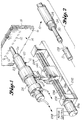
- a puller tool 10 is shown in the process of cold expanding a hole 12 in a workpiece 14.
- the workpiece 14 may constitute a pair of members 16, 18 which are to be secured together by fasteners (bolts, rivets, etc.) which extend through the openings 12.
- each opening 12 is actually two openings in axial alignment with each other.
- One opening is in member 16 and the other is in member 18.
- Tool 10 includes an elongated housing 20.
- Housing 20 includes an elongated tubular front portion 22 and an elongated tubular rear portion 24.
- Front portion 22 includes a nose portion 26.
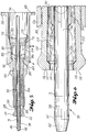
- An elongated tubular sleeve holder 28 (Fig. 3) is positioned within the front portion 22.
- An elongated tubular sleeve stop 30 (Fig. 3) is positioned within the sleeve holder 28.
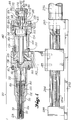
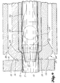
- An elongated mandrel 32 is positioned within sleeve stop 30.
- Mandrel 32 includes a rear end portion 34, a small diameter portion 36, an increasing diameter portion 38, a maximum diameter portion 40 and a tapered nose portion 42.
- Mandrel 32 has an extended position in which portions 38, 40 and 42, and a forward end part of portion 36 are positioned forwardly of nose portion 26 and sleeve holder 28.
- the inner end portion 34 is threaded at 44.
- a radial flange 46 separates threaded portion 44 and small diameter portion 36.
- Flange 46 has wrench flats 48 at its outer periphery.
- the front portion 22 of the tool housing 20 is a single member including a rear end mounting flange 50.
- Flange 50 is a radial flange and it includes a circular array of machine bolt receiving openings 52.
- Housing member 22 is a tubular member which varies in diameter along its length, inside as well as outside. Immediately forwardly of flange 50, housing member 22 extends as a constant diameter (outside) section 54. It then steps down to a relatively short smaller diameter (outside) section 56. Then, it steps down to the nose portion 26. Nose portion 26 is a smaller diameter (outside) section of substantial length. Internally, housing member 22 includes a first small diameter 58 within nose portion 26.
- section 56 Within section 56 it includes a slightly larger second diameter 60. Within the front part of section 54 it includes a yet larger third diameter 62. Near the longitudinal center of section 54 there is a larger fourth diameter 64. Immediately rearwardly of diameter 64 there is a larger fifth diameter 66. Rearwardly of diameter 66 there is a still larger sixth diameter 68. In the region of diameter 66 the inner sidewall of member 22 is threaded at 70. These threads mate with external threads 72 on a removable separator wall 74 (Fig. 3). As will hereinafter be described in greater detail, a shoulder 79 (Fig. 19) is formed where diameter 64 meets diameter 62. This shoulder 79 defines the forward boundary of an annular cavity in which the base 80 of sleeve stop 30 is received.
- shoulder 82 is formed where diameter 62 meets diameter 60. As will also be hereinafter described in more detail, shoulder 82 defines the forward end wall of a piston chamber or cylinder. The forward end of nose portion 26 includes a forwardly diverging internal surface 84. This surface 84 is a cam surface. Its function will be hereinafter described in some detail.
- Separator wall 74 is inserted into housing part 22 through a rear opening 76. It is moved forwardly and rotated to screw the threads 72 into the threads 70. Rotation continues until member 74 contacts base 80 of sleeve stop 30.
- the sleeve holder 28 is shown to be tubular and to vary in diameter both inside and outside. Its largest outside diameter is at the rear of the tool holder 28 where it includes a piston 86. Piston 86 includes a rear radial wall or surface 88 and a front radial wall or surface 90. It also includes a peripheral groove 93 in which a seal ring (not shown) is received. The outside diameter of piston 86 substantially equals diameter 62. Forwardly of piston 86, sleeve holder 28 includes a section 92 which is substantially equal to diameter 60. Piston 86 and most of section 92 are circumferentially continuous.
- the sleeve holder 28 is divided by a plurality of longitudinal slots into a plurality of longitudinal fingers.
- the fingers 100, 102 are on a diametrically opposite sides of section 94.
- the slots 96, 98 are also on diametrically opposite sides of the section 94.
- the fingers 100, 102 are in the nature of leaf springs.
- the slots 96, 98 divide the section 94 into two parts, to form such fingers 100, 102. In the preferred embodiment, the slots 96, 98 perform an additional function.
- slots 96, 98 include forward portions 104 (also termed “cam cavities") which are wider than the diameters of the cams C.
- the slots 96, 98 include an elongated main portion, also designated 96, 98. The width of the main portions 96, 98 is smaller than the diameter of the cams C.
- Cam surfaces 106, 108 extend between the cam cavities 104 and the main portions 96, 98 of the slots 96, 98.
- Jaws 110, 112 radially outwardly bound a central sleeve receiving end opening 114.
- Jaws 110, 112 include end surfaces 116, 118 which in use of the puller tool are in abutting engagement with a workpiece 14 immediately surrounding a hole in the workpiece 14.
- Jaws 110, 112 also include cam surfaces 120, 122 positioned to contact and be contacted by the cam surface 84 of nose portion 26, Jaws 116, 118 also include inside surfaces 124, 126 which contact outer surface portions of a flare 128 on a sleeve S.
- the sleeve stop 30 includes a circular base 80 at its rear end and a cylindrical tubular body extending forwardly from the base 80.
- the body is also designated 30 and it has a substantially constant outside diameter and a substantially constant inside diameter.
- the forward end ,of sleeve stop 30 includes a first portion which lies in an axial plane and a surrounding second portion 130 which is in the nature of a bevel.
- the bevel is a frustum of a 45° cone.
- Surface 130 confronts surfaces 124, 126 of sleeve holder 28 and either contacts or nearly contacts such surfaces when the sleeve holder 28 is retracted.
- the sleeve holder 28 is inserted into housing member 22 through end opening 76.
- the sleeve stop 30 is inserted through opening 76 and into and through the sleeve holder 28.
- Sleeve stop 30 is moved forwardly until its base 80 is against shoulder 79.
- Base 80 includes a peripheral groove 81 (Fig. 25) and a seal ring is positioned within said groove before sleeve stop 30 is inserted into the housing part 22.
- barrier wall 74 is inserted through opening 76 and is moved to the threads 70. Barrier wall 74 is rotated to cause its thread 72 to screw into the threads 70. Barrier wall 74 is rotated until it is against base 80.
- the mandrel 32 is inserted through opening 76, through the central opening in wall 74, and through the interior of sleeve stop 30. This assembles together the components which are housed within housing part 22. More of the assembly will be described following a description of the rear portion of the puller tool 10.
- the piston 86 divides the cylinder or piston chamber into two working chambers.
- a first working chamber 132 (Fig. 4) is located forwardly of piston 86.
- a second working chamber 134 (Fig. 5) is located rearwardly of piston 86.
- fluid pressure is introduced into the rear working chamber 134 while the front working chamber 132 is vented, to cause a forward extension of the sleeve holder 28.
- Fluid pressure is introduced into the forward working chamber 132 while the rearward working chamber 134 is vented, to cause a rearward movement of the piston 86 and a rearward retraction of the sleeve holder 28.
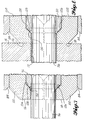
- the cams C are located within the cam cavities 104 (Fig. 10).
- the jaws 110, 112 are located within the interior of nose portion 26 (Fig. 10).
- the jaws 110, 112 are contracted and give the end portion of the sleeve holder 28 an outside diameter which is substantially equal to the inside diameter of nose portion 26.
- fluid pressure is introduced into the rear chamber 134 of the piston-cylinder unit while the front chamber 132 is vented, to cause a forward movement of the sleeve holder 28.
- the cam surfaces 106, 108 are moved towards and then into contact with the cams C.
- the cams C push against the cam surfaces 106, 108 and move the fingers 100, 102 radially apart.
- the cams C are moved into the main portions of the slots 96, 98 (Fig. 11). In the vicinity of the cams C, the slot width is increased by the cams C so as to be equal to the diameter of the cams C.
- the jaws 110, 112 are moved radially apart a considerable amount.
- puller tool 10 comprises a rear portion 140 that is connected to front portion 20.
- Rear portion 140 includes a tool mount 142 having a forward face to which the flange 50 is bolted.
- a linear piston-cylinder unit 144 is defined within rear portion 140. It may include a cylinder barrel 146 which is connected to the mount 142.
- a cylinder head 148 is shown to be housed within mount 142. Cylinder head 148 includes an end wall 150 and an annular seal groove in which an O-ring seal 151 is located.
- a piston head 152 is housed within cylinder barrel 146. Piston head 152 includes an annular seal groove in which a seal ring 154 is situated.
- Piston 152 divides the piston chamber into a first working chamber 156, positioned forwardly of piston 152, and a rear working chamber 158, positioned rearwardly of piston 152.
- a passageway 160 leads through the mount 152 and communicates with working chamber 156.
- a second passageway 162 extends through a sidewall of the housing and communicates with the second working chamber 158.
- Piston 152 may be termed the first piston or the mandrel pulling piston.
- a second piston-cylinder unit 164 is positioned rearwardly of the first piston-cylinder unit 144.
- the housing includes a radial wall 166 which is a rear wall for the front piston-cylinder unit 144 and a front wall for the rear piston-cylinder unit 164.
- Radial wall 166 includes a central opening 168.
- a tubular wall 170 extends rearwardly from radial wall 168. The rear end portion of tubular wall 170 is threaded at 172.
- a closure cap 174 is provided for the second piston-cylinder unit.
- Cap 174 includes a radial end wall 176 and a forwardly extending cylindrical wall 178. Cylindrical wall 178 includes threads 180 which engage threads 172.
- End closure 174 is mated with threads 172 and then is rotated until the end wall 176 is substantially against the end of tubular portion 170.
- a fluid delivery/return opening 182 is provided in wall 176. It is through this opening that fluid pressure is selectively introduced and then vented.
- Piston-cylinder unit 164 includes a piston 184 having a peripheral groove in which a seal ring 186 is located. Seal ring 186 seals against leakage between the piston and the cylinder wall.
- Piston 184 divides the cylinder or piston chamber into a front working chamber 188 and a rear working chamber 190 (Fig. 18).
- a piston rod 192 extends axially forward from a central part of piston 184. Piston rod 192 extends through opening 168 in end wall 166.
- a passageway 194 is provided in end wall 166. Passageway 194 connects working chamber 158 with working chamber 188. The front end of piston rod 192 is not connected to piston 152. Thus, piston 152 can be extended away from piston 192.
- the purpose of the second piston-cylinder unit 164 will hereinafter be described as a part of the operation description.
- Cylinder head 148 includes a central opening 196 and piston 152 includes a mandrel mount 198 which extends forwardly from piston 152 through the opening 196.
- the forward end of mandrel mount 198 includes a threaded axial opening into which the threaded rear end portion of the mandrel is received.
- a mandrel 32 can be connected to the mandrel mount 198 when front end portion 20 is removed. Then, front end portion 20 can be moved rearwardly over the mandrel 32 until flange 50 is against the front face of the mount 142. Then, the bolts 53 can be installed for the purpose of connecting housing part 22 to the mount 142.
- This mechanism includes a housing 200 which may comprise a first housing member 210 and a second housing member 212.
- housing member 210 is formed to include a channel which has a forward wall 214 and a pair of sidewalls 216, 218.
- Housing member 212 forms a rear wall for the channel.
- the channel and member 212 together define a longitudinal passageway 220 in the housing 200.
- the housing 200 is elongated in the vertical direction and the passageway 220 is also elongated in the vertical direction.
- Passageway 220 functions to guide the sleeves S through the passageway 220 to a holding station 224 at the lower end of the housing 200.
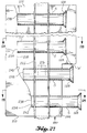
- the sleeves S are mounted on a carrier 226.
- Carrier 226 may be made of plastic and includes an elongated web 228 and a plurality of pairs of tabs 230, 232. As best shown by Figs. 28, 36 and 37, the tabs 230, 232 are connected to opposite edge portions of the web 228.
- the web 228 and tabs 230, 232 are constructed from sheet material which is initially flat.
- the tabs 230, 232 are initially in the same plane with the web 228.
- the sheet material is cut to form the web 228, the tabs 230, 232 and openings 234, 236 in the tabs 230, 232.
- the openings are slotted at their free ends.
- the diameter of the openings 234, 236 is slightly smaller than the outside diameter of the sleeves S. As shown by Figs. 27-29 and 34-37, each sleeve S is inserted endwise through the openings 234, 236 in its tabs 230, 232.
- the sleeves S are spaced apart an even amount when they are mounted on the carrier 226. Initially, the sleeves S are substantially centered on the carrier 226. This is shown at the top of Fig. 27 and in Figs. 28, 36, and 37. As previously described, a flare 128 is provided at the rear end of each sleeve S. The opposite or front end 238 is confronted by the inner surface 240 of housing wall 218. Surface 240 is a cam surface. As shown by Fig. 27, as the carrier 226 and the sleeves S move longitudinally of passageway 220, there is contact between the end surfaces 238 of sleeves S and cam 240 which cams or moves the sleeves S rearwardly as they approach the holding station 224. As illustrated in Fig.
- the cam surface 240 is curved to progressively move laterally inwardly of the passageway 220.
- the cam surface 240 commences to curve below the second sleeve from the holding station 224.
- the first sleeve from the holding station 224 is shown partially moved rearwardly from a center position.
- the grip on the sleeves S provided by the tabs 230, 232 is a releasable grip. It allows the endwise movement of the sleeves S.
- housing 200 includes a window W out through which the rear end portions of the sleeves S move as the sleeves S are cammed rearwardly.
- a sleeve S When a sleeve S is at the holding station 224, it is held against further downward movement by contact with cradle surfaces 242, 244. When a sleeve S is at the holding station 224, it has lower side portions which are against the cradle surfaces 242, 244 and its rear surface 238 is against the lower portion of the cam surface 240.
- the passageway 220 includes a shallow channel 246 in which the carrier web 228 is received.
- Channel 246 serves to guide the carrier web 228 along a straight path through the passageway 220.
- This channel 246, and a narrow portion of the passageway 220 continue downwardly through the lower end of the housing 200, between the two portions of the cradle.
- housing 200 is moved up and down, such as by a linear air actuator 246 (Fig. 31).
- a piston 248 in air actuator 246 is extended to lower the housing 200 into a position which aligns a sleeve S at the holding station 224 with the mandrel 32 and sleeve holder 28 of the puller tool 10 (Figs. 34 and 35).
- the piston 248 is retracted to move the housing 200 up out of the way of the puller tool 10, to permit a forward movement of the puller tool towards an opening in a workpiece 14 (Figs. 1 and 9).
- a piston rod 250 may extend from piston 248 to a connection with housing part 210 (Figs. 30 and 31).
- Housing part 210 may include vertical guide grooves 251, 252 which receive suitable guide rails (not shown) which serve to mount and guide housing 200 for up and down movement between upper and lower positions.
- the sleeves S are advanced through the passageway 220 by means of an advance mechanism which is mounted on housing part 212.
- the advance mechanism includes a support 254 which is mounted for up and down travel along housing part 212.
- the up and down movement may be performed by an air actuator 256.
- Support 254 may be guided for up and down movement along housing member 212 by any suitable guide means.
- piston rod 258, which extends from piston 260 to a connection with support 254 may extend through a bushing which is supported in a fixed position by a bracket which extends rearwardly from housing part 212.
- housing part 212 and support 254 may include mating tracks and grooves serving to guide support 254 for straight line movement up and down relative to housing part 212.
- support 254 includes a cavity 262 in which an advance finger 264 is in at least in part housed.
- Advance finger 264 is mounted for pivotal movement about a pivot axis, such as by a pivot pin 266 which extends through an opening in a central portion of advance finger 264 and also extends through openings 268, 270 in side portions 272, 274 of the support 254 (Fig. 29).
- Advance finger 264 includes a first or forward end portion 276 and a second or rearward end portion 278.
- Support 254 includes a stop 280.
- a spring 282 is interconnected between rear end location 284 of advance finger 264 and a connector 286 carried by support 254.
- Spring 282 is a tension spring which normally pulls on the rear end portion 278 of advance finger 264, and pulls it against the stop 280. In this position, the forward end portion 276 extends into and spans across the passageway 220 (Figs. 28 and 29). A slot-like window 288 is provided in housing member 212 and the forward end portion 276 of advance finger 264 extends through this window.
- Fig. 31 shows the position of advance finger 276 when the piston 260 is extended and the support 254 is in a down position. The forward portion 276 of advance finger 264 is down on a sleeve S but does not prohibit removal of the sleeve by the puller tool 10 from the holding station 224.
- the piston 260 is retracted. This moves support 254 upwardly. Eventually the top surface of the front portion 276 of advance finger 264 will contact the sleeve S that is in the approach position one step removed from the holding station 224. As shown by Fig. 32, this contact will not prevent further upward movement of support 254.
- the advance finger 264 will pivot until its front portion 276 clears the sleeve S which is at the approach position. After advance finger 264 clears the sleeve S, the spring 282 will swing the advance finger 264 back into a position with its rear end portion 278 against the stop 280.
- the front end portion 276 will now be positioned between the sleeve S at the approach position and the sleeve S that is two steps removed from the holding station 224.
- support 254 will be moved downwardly and the forward portion 276 of advance finger 264 will be moved against the sleeve S that is at the approach position.
- the contact between the rear end portion 278 of advance finger 264 and the stop 280 will prevent rotation of advance finger 264 beyond the position shown in Fig. 33.
- the contact of finger portion 276 with the sleeve S will move such sleeve S down to the holding station 224.
- a sleeve S is shown to be positioned at the holding station 224, with its rear end portion projecting rearwardly out through the window W.
- Fuller tool 10 with mandrel 32 retracted and sleeve holder 28 extended and radially expanded, is shown positioned in axial alignment with the sleeve S.
- the tool 10 is moved axially towards housing 200, so as to move the rear end portion of sleeve S through the end opening 114 and into the interior of the sleeve holder 28. Then, fluid pressure is introduced through passage 182 into the working chamber behind piston 184 while working chamber 188 is vented.
- Sleeve S is internally lubricated by a solid film lubricant.
- This type of lubricant is sprayed on in liquid form and hardens.
- Many solid film lubricants are commercially available and each contain in general a composition of lead oxide, graphite and molybdenum disulfide. This lubricant film is capable of withstanding better than one hundred thousand psi.
- the use of the solid lubricant in combination with the sleeve makes it possible to work with much greater interference or with, in other words, less difference between mandrel and hole diameter, increasing the efficient degree of cold working and also the fatigue life of the fastener joint.
- the tool mount 142 is shown to be mounted for travel along a pair of guide rods 284, 286 which are at their ends secured to posts 288, 290.
- Posts 288, 290 project upwardly from a longitudinal base member 292.
- the mount 142 is moved back and forth along the guide rod: 284, 286 by any suitable drive mechanism.
- this drive mechanism is in the form of an elongated lead screw 294 which extends from a reversible electric motor 296, first through post 290, then through the space between posts 290 and 288, and then into post 288.
- the lead screw 294 is supported at its ends by suitable bearings, in conventional fashion.
- the base of mount 142 includes a nut internal meter (not shown) of conventional construction through which the lead screw passes. Rotation of lead screw 294 causes the nut member, and hence mount 142 and puller tool 10, to be moved lengthwise of the lead screw 294 and the guide rods 284, 286.
- the motor 296 is controlled by a suitable motor control circuit which is not a part of the present invention.
- Base 292 for the puller tool 10 and housing 210 for the sleeve loader 200 are mounted on robot arms, or the like.
- the robots or other mechanisms are moved to position the sleeve bolder 200 forwardly of the puller tool, and to position the puller tool in a position to pick up a sleeve, and to move the puller tool for the purpose of picking up the sleeve, and then moving the puller tool assembly away from the sleeve loader, and the sleeve loader out from in front of the openings 12, and then moving the puller tool 10 to insert the mandrel and the sleeve carried by the mandrel into an opening 12, followed by the tool 10 being held in position and the mandrel being retracted to expand the sleeve S and cold expand the hole 12 in which the sleeve S is located.
- proximity sensors will be used to provide input commands for the computer which controls the robots and the operation of the puller tool 10.
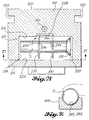
- Figs. 38 and 39 illustrate a modified construction of the puller unit 300.
- Fuller unit 300 is mounted on a support 302 which in turn is mounted on an elongated lead screw 304 which is selectively rotated in either direction by a motor 306.
- the construction of the lead screw assembly 304, 306 is not a part of the invention and so the details of this mechanism will not be described. However, as explained in connection with Figs. 1 and 4, rotation of the lead screw 304 in one direction causes the puller unit 300 to advance along the lead screw and guide structure for the puller unit 300. Rotation of the lead screw 304 in the opposite direction causes the puller unit to move rearwardly along the lead screw.
- Lead screw assembly 304, 306 is mounted on a base 292 which may be mounted on a robot arm or other mechanism designed to position the puller tool, in the manner described above.
- the puller unit 300 includes a forward housing member 308 which has a small diameter forward portion 310, a larger diameter rear portion 312, a generally conical transition portion 314 and a rear end flange 316. Flange 316 mates with the forward end of a central housing part 318. A retainer ring 320 is used to secure housing part 308 to housing part 318.
- the puller unit 300 includes a rear housing part 322 having a small diameter, tubular forward portion 324 and a tubular rear portion 326.
- An elongated tubular sleeve holder 328 is provided at the forward end of a member 330.
- the rear portion 332 of member 330 is connected to the forward end of a tubular member 334.
- Member 334 includes a radial flange 336 at its rear end.
- Flange 336 includes a circumferential groove in which is situated an annular seal ring 338.
- Flange 336 serves as a piston and divides an annular chamber space formed radially between members 318 and 334, into two working chambers 340, 342.
Landscapes
- Engineering & Computer Science (AREA)
- Chemical & Material Sciences (AREA)
- Mechanical Engineering (AREA)
- Crystallography & Structural Chemistry (AREA)
- Materials Engineering (AREA)
- Metallurgy (AREA)
- Organic Chemistry (AREA)
- Hand Tools For Fitting Together And Separating, Or Other Hand Tools (AREA)
- Non-Reversible Transmitting Devices (AREA)
- Gripping On Spindles (AREA)
Applications Claiming Priority (3)
| Application Number | Priority Date | Filing Date | Title |
|---|---|---|---|
| PCT/EP1992/000912 WO1992020148A1 (fr) | 1991-04-25 | 1992-04-25 | Circuit pour amplificateur a regulation |
| US07/920,602 US5305627A (en) | 1992-07-27 | 1992-07-27 | Split sleeve cold expansion |
| US920602 | 1992-07-27 |
Publications (2)
| Publication Number | Publication Date |
|---|---|
| EP0581385A1 true EP0581385A1 (fr) | 1994-02-02 |
| EP0581385B1 EP0581385B1 (fr) | 1997-05-21 |
Family
ID=25444039
Family Applications (1)
| Application Number | Title | Priority Date | Filing Date |
|---|---|---|---|
| EP93202220A Expired - Lifetime EP0581385B1 (fr) | 1992-04-25 | 1993-07-26 | Expansion à froid pour douille fendue |
Country Status (4)
| Country | Link |
|---|---|
| US (1) | US5305627A (fr) |
| EP (1) | EP0581385B1 (fr) |
| AT (1) | ATE153267T1 (fr) |
| DE (1) | DE69310828T2 (fr) |
Cited By (9)
| Publication number | Priority date | Publication date | Assignee | Title |
|---|---|---|---|---|
| US6531227B1 (en) | 1999-07-09 | 2003-03-11 | Oce-Technologies B.V. | Intermediate medium for transferring a toner image from an imaging medium to a final receiving material |
| US8302448B2 (en) | 2006-04-24 | 2012-11-06 | Airbus Operations Sas | Expansion tool and method for cold expansion of holes |
| WO2013116111A1 (fr) * | 2012-01-30 | 2013-08-08 | Fatigue Technology, Inc. | Systèmes d'installation/de traitement à puce, composants, et leurs procédés de fonctionnement |
| WO2014012153A1 (fr) * | 2012-07-20 | 2014-01-23 | Maksimov Yordan | Outil et dispositif pour la dilatation à froid de trous |
| EP2671672A3 (fr) * | 2012-06-04 | 2015-04-08 | Airbus Defence and Space GmbH | Dispositif de préhension pour la préhension d'un mandrin et d'une douille d'un outil de formage pour l'élargissement d'un trou |
| WO2015153195A1 (fr) * | 2014-04-04 | 2015-10-08 | Brady Worldwide, Inc. | Machine d'application de manchon et procédé de fonctionnement associé |
| CN105234301A (zh) * | 2015-10-21 | 2016-01-13 | 洛阳隆华传热节能股份有限公司 | 一种用于冷凝器管束椭圆管的胀管装置的操作方法 |
| CN108754121A (zh) * | 2018-06-13 | 2018-11-06 | 江苏大学 | 一种孔壁激光喷丸复合挤压强化的装置及其方法 |
| US10569399B1 (en) | 2017-11-03 | 2020-02-25 | Brady Worldwide, Inc. | Wire sleeve hand application tool |
Families Citing this family (34)
| Publication number | Priority date | Publication date | Assignee | Title |
|---|---|---|---|---|
| US5479829A (en) * | 1994-12-16 | 1996-01-02 | Northrop Grumman Corporation | Method for quantitative inspection of cold-expanded fastener holes |
| US5613395A (en) * | 1995-02-09 | 1997-03-25 | Gemcor Engineering Corp. | Coldworking tool automation |
| CA2301119A1 (fr) * | 1997-08-19 | 1999-02-25 | Atoma International Inc. | Outil d'extraction des manchons de retenue d'appui-tete |
| US7375277B1 (en) * | 2000-06-26 | 2008-05-20 | Fatigue Technology, Inc. | Double flanged bushings and installation methods |
| US7059816B2 (en) | 2001-11-09 | 2006-06-13 | Textron Inc. | Nut plate |
| US7114900B2 (en) * | 2001-11-09 | 2006-10-03 | Textron Inc. | Push-type rivetless nut plate and method and apparatus for installing same |
| US7024908B2 (en) * | 2003-07-10 | 2006-04-11 | Fatigue Technology, Inc. | Fatigue enhancement of material surrounding openings in workpieces |
| US7448652B2 (en) * | 2003-07-31 | 2008-11-11 | Fatigue Technology Inc. | Tubular metal fitting expandable in a wall opening and method of installation |
| US20070053761A1 (en) * | 2004-08-03 | 2007-03-08 | Scott Cohen | Sealed rivetless nut plate |
| US20070110541A1 (en) * | 2005-10-28 | 2007-05-17 | Fatigue Technology, Inc. | Radially displaceable bushing for retaining a member relative to a structural workpiece |
| EP3199292B1 (fr) | 2005-12-28 | 2020-03-11 | Fatigue Technology, Inc. | Ensemble mandrin et procédé de son utilisation |
| AU2007204888B2 (en) * | 2006-01-11 | 2012-08-16 | Fatigue Technology, Inc. | Bushing kits, bearings, and methods of installation |
| CA2535577C (fr) * | 2006-02-08 | 2013-08-13 | Nav-Aids Ltee | Adaptateur d'essai pour prise statique d'aeronef |
| US20070227215A1 (en) * | 2006-02-27 | 2007-10-04 | Surface Technology Holdings, Ltd. | Method and apparatus for preventing or arresting crack development and propagation |
| WO2007127399A2 (fr) | 2006-04-27 | 2007-11-08 | Fatigue Technology, Inc. | Caractéristiques géométriques de décharge pour vague dans des éléments structuraux dilatables radialement à l'intérieur de pièces |
| JP5258751B2 (ja) * | 2006-04-27 | 2013-08-07 | ファティーグ テクノロジー インコーポレイテッド | アラインメント装置およびその使用方法 |
| DE102006022702B3 (de) * | 2006-05-12 | 2007-09-27 | Eads Deutschland Gmbh | Verfahren und Vorrichtung zur Kaltbearbeitung von Löchern |
| US20080005887A1 (en) * | 2006-05-26 | 2008-01-10 | Fatigue Technology, Inc. | Elongated member/radially expandable member assembly and methods of assembling the same |
| US7958766B2 (en) * | 2006-06-29 | 2011-06-14 | Fatigue Technology, Inc. | Self-aligning tools and a mandrel with retention sleeve |
| KR101468399B1 (ko) | 2006-08-28 | 2014-12-03 | 퍼티구 테크놀로지 인코포레이티드 | 설치/처리 시스템 및 이를 사용하는 방법 |
| US7575404B2 (en) * | 2006-11-01 | 2009-08-18 | Sps Technologies, Llc | Nut plate fastener assembly for composite materials |
| EP2158409A2 (fr) * | 2007-05-15 | 2010-03-03 | Fatigue Technology, Inc. | Collier extensible installé en aveugle et élément interne fileté |
| EP2210001B1 (fr) | 2007-10-16 | 2017-08-02 | Fatigue Technology, Inc. | Ensemble attache expansible à collier déformé |
| US10010983B2 (en) * | 2008-03-07 | 2018-07-03 | Fatigue Technology, Inc. | Expandable member with wave inhibitor and methods of using the same |
| BG66052B1 (bg) * | 2008-03-25 | 2010-12-30 | Йордан МАКСИМОВ | Инструмент за обработване на скрепителни отвори |
| EP2318726B1 (fr) * | 2008-07-18 | 2015-09-02 | Fatigue Technology, Inc. | Ensemble plaque à écrou et procédés d'utilisation de celui-ci |
| EP2417369B1 (fr) | 2009-04-10 | 2014-04-02 | Fatigue Technology, Inc. | Ensemble installable avec manchon extensible et un élément de fixation avec mandrin de traction |
| EP2513499B1 (fr) | 2009-12-16 | 2015-04-08 | Fatigue Technology, Inc. | Ensemble plaque à écrou modulaires et procédés d'utilisation de celui-ci |
| CN102061362B (zh) * | 2010-12-24 | 2013-06-12 | 江苏大学 | 一种环形激光冲击强化紧固孔的方法和装置 |
| WO2012167136A2 (fr) | 2011-06-03 | 2012-12-06 | Fatigue Technology, Inc. | Inhibiteurs de fissuration expansibles et leurs procédés d'utilisation |
| US9114449B2 (en) | 2011-06-15 | 2015-08-25 | Fatigue Technology, Inc. | Modular nut plates with closed nut assemblies |
| WO2013040661A1 (fr) * | 2011-09-19 | 2013-03-28 | Махимов Консулт Ад | Dispositif et outillage d'élargissement à froid des trous de fixation |
| DE102012010793A1 (de) | 2012-06-01 | 2013-12-05 | Eads Deutschland Gmbh | Umformwerkzeug zum Aufweiten einer Öffnung mit einer Aufweitvorrrichtung |
| CN113477797A (zh) * | 2021-05-25 | 2021-10-08 | 成都飞机工业(集团)有限责任公司 | 一种基于数控机床的自动冷扩孔设备及其使用方法 |
Citations (4)
| Publication number | Priority date | Publication date | Assignee | Title |
|---|---|---|---|---|
| US3892121A (en) * | 1973-09-12 | 1975-07-01 | Boeing Co | Apparatus for cold-working holes |
| US4423619A (en) * | 1981-06-15 | 1984-01-03 | Fatigue Technology, Inc. | Apparatus and method for prestressing a countersunk fastener hole |
| US4557033A (en) * | 1983-07-11 | 1985-12-10 | Fatigue Technology, Inc. | Method of cold expanding and sizing fastener holes |
| US5127254A (en) * | 1991-07-10 | 1992-07-07 | Fatigue Technology, Inc. | Method and apparatus for split sleeve cold expansion of openings in structural members |
Family Cites Families (10)
| Publication number | Priority date | Publication date | Assignee | Title |
|---|---|---|---|---|
| US3566662A (en) * | 1969-04-28 | 1971-03-02 | Boeing Co | Coldworking method and apparatus |
| US4187708A (en) * | 1977-04-11 | 1980-02-12 | Industrial Wire & Metal Forming, Inc. | Pulling apparatus and method |
| US4524600A (en) * | 1982-02-10 | 1985-06-25 | Champoux Robert L | Apparatus for prestressing fastener holes |
| US4425780A (en) * | 1982-02-10 | 1984-01-17 | Fatigue Technology, Inc. | Apparatus having extended prestressing and sleeve retaining devices for prestressing countersunk fastener holes and method |
| US4471643A (en) * | 1982-02-10 | 1984-09-18 | Fatigue Technology, Inc. | Method and apparatus for prestressing fastener holes |
| US4583388A (en) * | 1983-09-30 | 1986-04-22 | West Coast Industries, Inc. | Method and apparatus for hole coldworking |
| US4606455A (en) * | 1984-08-17 | 1986-08-19 | Duo-Fast Corporation | Collated fastener strip |
| US4640114A (en) * | 1985-01-29 | 1987-02-03 | Grumman Aerospace Corporation | Automated process for cold working holes |
| GB8906231D0 (en) * | 1989-03-17 | 1989-05-04 | Avdel Systems Ltd | Pull-through blind fastener installation apparatus and method |
| JPH0741543Y2 (ja) * | 1989-07-28 | 1995-09-27 | オプトエンジニアリング株式会社 | リベット保持体 |
-
1992
- 1992-07-27 US US07/920,602 patent/US5305627A/en not_active Expired - Lifetime
-
1993
- 1993-07-26 EP EP93202220A patent/EP0581385B1/fr not_active Expired - Lifetime
- 1993-07-26 AT AT93202220T patent/ATE153267T1/de not_active IP Right Cessation
- 1993-07-26 DE DE69310828T patent/DE69310828T2/de not_active Expired - Lifetime
Patent Citations (4)
| Publication number | Priority date | Publication date | Assignee | Title |
|---|---|---|---|---|
| US3892121A (en) * | 1973-09-12 | 1975-07-01 | Boeing Co | Apparatus for cold-working holes |
| US4423619A (en) * | 1981-06-15 | 1984-01-03 | Fatigue Technology, Inc. | Apparatus and method for prestressing a countersunk fastener hole |
| US4557033A (en) * | 1983-07-11 | 1985-12-10 | Fatigue Technology, Inc. | Method of cold expanding and sizing fastener holes |
| US5127254A (en) * | 1991-07-10 | 1992-07-07 | Fatigue Technology, Inc. | Method and apparatus for split sleeve cold expansion of openings in structural members |
Cited By (12)
| Publication number | Priority date | Publication date | Assignee | Title |
|---|---|---|---|---|
| US6531227B1 (en) | 1999-07-09 | 2003-03-11 | Oce-Technologies B.V. | Intermediate medium for transferring a toner image from an imaging medium to a final receiving material |
| US8302448B2 (en) | 2006-04-24 | 2012-11-06 | Airbus Operations Sas | Expansion tool and method for cold expansion of holes |
| CN101437649B (zh) * | 2006-04-24 | 2013-06-12 | 空中客车法国公司 | 用于孔的冷扩张的扩张工具 |
| WO2013116111A1 (fr) * | 2012-01-30 | 2013-08-08 | Fatigue Technology, Inc. | Systèmes d'installation/de traitement à puce, composants, et leurs procédés de fonctionnement |
| EP2671672A3 (fr) * | 2012-06-04 | 2015-04-08 | Airbus Defence and Space GmbH | Dispositif de préhension pour la préhension d'un mandrin et d'une douille d'un outil de formage pour l'élargissement d'un trou |
| WO2014012153A1 (fr) * | 2012-07-20 | 2014-01-23 | Maksimov Yordan | Outil et dispositif pour la dilatation à froid de trous |
| WO2015153195A1 (fr) * | 2014-04-04 | 2015-10-08 | Brady Worldwide, Inc. | Machine d'application de manchon et procédé de fonctionnement associé |
| US9944422B2 (en) | 2014-04-04 | 2018-04-17 | Brady Worldwide, Inc. | Sleeve applicator machine and related method of operation |
| CN105234301A (zh) * | 2015-10-21 | 2016-01-13 | 洛阳隆华传热节能股份有限公司 | 一种用于冷凝器管束椭圆管的胀管装置的操作方法 |
| US10569399B1 (en) | 2017-11-03 | 2020-02-25 | Brady Worldwide, Inc. | Wire sleeve hand application tool |
| CN108754121A (zh) * | 2018-06-13 | 2018-11-06 | 江苏大学 | 一种孔壁激光喷丸复合挤压强化的装置及其方法 |
| CN108754121B (zh) * | 2018-06-13 | 2019-08-27 | 江苏大学 | 一种孔壁激光喷丸复合挤压强化的装置及其方法 |
Also Published As
| Publication number | Publication date |
|---|---|
| US5305627A (en) | 1994-04-26 |
| EP0581385B1 (fr) | 1997-05-21 |
| ATE153267T1 (de) | 1997-06-15 |
| DE69310828D1 (de) | 1997-06-26 |
| DE69310828T2 (de) | 1997-09-18 |
Similar Documents
| Publication | Publication Date | Title |
|---|---|---|
| EP0581385B1 (fr) | Expansion à froid pour douille fendue | |
| EP0086344B1 (fr) | Méthode et appareil pour précontraindre un trou de fixation chanfreiné | |
| US5127254A (en) | Method and apparatus for split sleeve cold expansion of openings in structural members | |
| US5341559A (en) | Method and apparatus for securing a tubular bushing in a circular opening | |
| EP0513898A1 (fr) | Procédé et dispositif pour joindre un manchon tubulaire dans une ouverture circulaire | |
| US4423619A (en) | Apparatus and method for prestressing a countersunk fastener hole | |
| US5433100A (en) | Apparatus for split sleeve and tubular bushing cold expansion | |
| US8726486B2 (en) | System for loading collars onto bolts in large-scale manufacturing operations | |
| EP1644142B1 (fr) | Renforcement de la resistance du materiau entourant des ouvertures dans des pieces | |
| JPH0327838A (ja) | 締付具取付装置 | |
| US4524600A (en) | Apparatus for prestressing fastener holes | |
| WO2020244753A1 (fr) | Outil de pose d'écrous de rivet aveugle | |
| US7047618B2 (en) | Single stroke O-ring insertion device | |
| EP0388117B1 (fr) | Méthode et appareillage pour faire passer l'installation aveugle d'un élément tubulaire | |
| US11027377B2 (en) | Ring installation device | |
| US5400942A (en) | Automatic fastener feed apparatus and method | |
| US20070157453A1 (en) | Self-aligning collar swaging system for airplane panel bolts | |
| US5155892A (en) | Hydraulic cylinder assembly process and machine | |
| KR100463856B1 (ko) | 리벳팅장치 | |
| WO2004024365A1 (fr) | Outil pour le tulipage de tuyaux | |
| US5788140A (en) | Device for driving inserts into pieces of sheet metal | |
| JP7211124B2 (ja) | 缶体加工方法及び缶体加工装置 | |
| CN121267086B (zh) | 应用于大底脚螺纹抽芯铆钉的铆接设备 | |
| US4339866A (en) | Method of connecting a tube to a flange | |
| JPH10138055A (ja) | C形止め輪挿入機 |
Legal Events
| Date | Code | Title | Description |
|---|---|---|---|
| PUAI | Public reference made under article 153(3) epc to a published international application that has entered the european phase |
Free format text: ORIGINAL CODE: 0009012 |
|
| AK | Designated contracting states |
Kind code of ref document: A1 Designated state(s): AT BE CH DE DK ES FR GB GR IE IT LI LU MC NL PT SE |
|
| 17P | Request for examination filed |
Effective date: 19940727 |
|
| 17Q | First examination report despatched |
Effective date: 19951222 |
|
| GRAG | Despatch of communication of intention to grant |
Free format text: ORIGINAL CODE: EPIDOS AGRA |
|
| GRAH | Despatch of communication of intention to grant a patent |
Free format text: ORIGINAL CODE: EPIDOS IGRA |
|
| GRAH | Despatch of communication of intention to grant a patent |
Free format text: ORIGINAL CODE: EPIDOS IGRA |
|
| GRAA | (expected) grant |
Free format text: ORIGINAL CODE: 0009210 |
|
| AK | Designated contracting states |
Kind code of ref document: B1 Designated state(s): AT BE CH DE DK ES FR GB GR IE IT LI LU MC NL PT SE |
|
| PG25 | Lapsed in a contracting state [announced via postgrant information from national office to epo] |
Ref country code: NL Free format text: LAPSE BECAUSE OF FAILURE TO SUBMIT A TRANSLATION OF THE DESCRIPTION OR TO PAY THE FEE WITHIN THE PRESCRIBED TIME-LIMIT Effective date: 19970521 Ref country code: LI Effective date: 19970521 Ref country code: IT Free format text: LAPSE BECAUSE OF FAILURE TO SUBMIT A TRANSLATION OF THE DESCRIPTION OR TO PAY THE FEE WITHIN THE PRE;WARNING: LAPSES OF ITALIAN PATENTS WITH EFFECTIVE DATE BEFORE 2007 MAY HAVE OCCURRED AT ANY TIME BEFORE 2007. THE CORRECT EFFECTIVE DATE MAY BE DIFFERENT FROM THE ONE RECORDED.SCRIBED TIME-LIMIT Effective date: 19970521 Ref country code: GR Free format text: LAPSE BECAUSE OF FAILURE TO SUBMIT A TRANSLATION OF THE DESCRIPTION OR TO PAY THE FEE WITHIN THE PRESCRIBED TIME-LIMIT Effective date: 19970521 Ref country code: ES Free format text: THE PATENT HAS BEEN ANNULLED BY A DECISION OF A NATIONAL AUTHORITY Effective date: 19970521 Ref country code: DK Effective date: 19970521 Ref country code: CH Effective date: 19970521 Ref country code: BE Effective date: 19970521 Ref country code: AT Effective date: 19970521 |
|
| REF | Corresponds to: |
Ref document number: 153267 Country of ref document: AT Date of ref document: 19970615 Kind code of ref document: T |
|
| REG | Reference to a national code |
Ref country code: CH Ref legal event code: EP |
|
| REF | Corresponds to: |
Ref document number: 69310828 Country of ref document: DE Date of ref document: 19970626 |
|
| ET | Fr: translation filed | ||
| PG25 | Lapsed in a contracting state [announced via postgrant information from national office to epo] |
Ref country code: LU Free format text: LAPSE BECAUSE OF NON-PAYMENT OF DUE FEES Effective date: 19970726 Ref country code: IE Free format text: LAPSE BECAUSE OF NON-PAYMENT OF DUE FEES Effective date: 19970726 |
|
| PG25 | Lapsed in a contracting state [announced via postgrant information from national office to epo] |
Ref country code: SE Effective date: 19970821 Ref country code: PT Effective date: 19970821 |
|
| NLV1 | Nl: lapsed or annulled due to failure to fulfill the requirements of art. 29p and 29m of the patents act | ||
| REG | Reference to a national code |
Ref country code: CH Ref legal event code: PL |
|
| PG25 | Lapsed in a contracting state [announced via postgrant information from national office to epo] |
Ref country code: MC Free format text: LAPSE BECAUSE OF NON-PAYMENT OF DUE FEES Effective date: 19980131 |
|
| PLBE | No opposition filed within time limit |
Free format text: ORIGINAL CODE: 0009261 |
|
| 26N | No opposition filed | ||
| REG | Reference to a national code |
Ref country code: GB Ref legal event code: IF02 |
|
| PGFP | Annual fee paid to national office [announced via postgrant information from national office to epo] |
Ref country code: GB Payment date: 20120725 Year of fee payment: 20 |
|
| PGFP | Annual fee paid to national office [announced via postgrant information from national office to epo] |
Ref country code: FR Payment date: 20120731 Year of fee payment: 20 Ref country code: DE Payment date: 20120727 Year of fee payment: 20 |
|
| REG | Reference to a national code |
Ref country code: DE Ref legal event code: R071 Ref document number: 69310828 Country of ref document: DE |
|
| REG | Reference to a national code |
Ref country code: GB Ref legal event code: PE20 Expiry date: 20130725 |
|
| PG25 | Lapsed in a contracting state [announced via postgrant information from national office to epo] |
Ref country code: DE Free format text: LAPSE BECAUSE OF EXPIRATION OF PROTECTION Effective date: 20130727 |
|
| PG25 | Lapsed in a contracting state [announced via postgrant information from national office to epo] |
Ref country code: GB Free format text: LAPSE BECAUSE OF EXPIRATION OF PROTECTION Effective date: 20130725 |