EP0581514A2 - Méthode pour cartographie d'images dans un espace linéaire - Google Patents
Méthode pour cartographie d'images dans un espace linéaire Download PDFInfo
- Publication number
- EP0581514A2 EP0581514A2 EP93305724A EP93305724A EP0581514A2 EP 0581514 A2 EP0581514 A2 EP 0581514A2 EP 93305724 A EP93305724 A EP 93305724A EP 93305724 A EP93305724 A EP 93305724A EP 0581514 A2 EP0581514 A2 EP 0581514A2
- Authority
- EP
- European Patent Office
- Prior art keywords
- image
- values
- palette
- colours
- colour
- Prior art date
- Legal status (The legal status is an assumption and is not a legal conclusion. Google has not performed a legal analysis and makes no representation as to the accuracy of the status listed.)
- Withdrawn
Links
Images



Classifications
-
- G—PHYSICS
- G09—EDUCATION; CRYPTOGRAPHY; DISPLAY; ADVERTISING; SEALS
- G09G—ARRANGEMENTS OR CIRCUITS FOR CONTROL OF INDICATING DEVICES USING STATIC MEANS TO PRESENT VARIABLE INFORMATION
- G09G5/00—Control arrangements or circuits for visual indicators common to cathode-ray tube indicators and other visual indicators
- G09G5/02—Control arrangements or circuits for visual indicators common to cathode-ray tube indicators and other visual indicators characterised by the way in which colour is displayed
- G09G5/06—Control arrangements or circuits for visual indicators common to cathode-ray tube indicators and other visual indicators characterised by the way in which colour is displayed using colour palettes, e.g. look-up tables
-
- H—ELECTRICITY
- H04—ELECTRIC COMMUNICATION TECHNIQUE
- H04N—PICTORIAL COMMUNICATION, e.g. TELEVISION
- H04N1/00—Scanning, transmission or reproduction of documents or the like, e.g. facsimile transmission; Details thereof
- H04N1/46—Colour picture communication systems
- H04N1/64—Systems for the transmission or the storage of the colour picture signal; Details therefor, e.g. coding or decoding means therefor
- H04N1/644—Systems for the transmission or the storage of the colour picture signal; Details therefor, e.g. coding or decoding means therefor using a reduced set of representative colours, e.g. each representing a particular range in a colour space
Definitions
- the present invention relates generally to image processing and, more particularly, is directed to methods for eliminating artifacts associated with image display nonlinearities.
- Image display nonlinearities cause colour shifts and mottle in images mapped to a palette with conventional mapping algorithms well known in the art.
- a method for mapping pixels of stored image colours of a digitised image to palette colours in a image processing system comprising the steps of: retrieving representations of the image colours stored in the system; and translating the stored image colours into values linearly proportional to lumens emitted when the image is displayed.
- the palette colours can be monochromatic or multichromatic.
- the method preferably includes the step of determining an error for each of the pixels associated with the translating of the retrieved representations arising from a finite number of the palette colours.
- the method includes the step of diffusing the error by subtracting it from values of the pixels of stored image colours proximal each of the pixels.
- the steps of measuring and diffusing the error are executed in a domain comprising values linearly proportional to the lumens emitted when the image is displayed.
- the method includes the step of adding a dither pattern to the image.
- the step of adding a dither pattern is preferably executed in a domain comprising values linearly proportional to the lumens when the image is displayed.
- the present invention thus provides a method for eliminating colour shift and mottle in image mapped to a palette in which method mapping occurs in a space where numbers are linearly related to display lumens.
- Such linear mapping is made practical in accordance with the invention by a two-step lookup method of finding closest palette colours and by an optimisation system and method for deriving such lookup tables.
- a method for matching an image colour defined by three colour vectors to a palette colour of a finite palette in an image processing system comprising the steps of: converting each of the vectors to a corresponding converted vector with at least one non-linearfunction; establishing a lookup table of colours of the finite palette; and selecting as a function of each of the converted vectors a palette colour of the finite palette from the lookup table as a match to the image colour.
- the method includes the step of combining each converted vector into a single vector to form a pointer to the lookup table.
- the step of selecting comprises selecting the palette colour with the pointer.
- the three colour vectors preferably include a luminance vector and two colour vectors.
- the present invention thus provides an image mapping method which can eliminate artifacts arising from image display nonlinearities.
- the methods of the present invention employ linear mapping but remain practical in terms of storage and processor speed requirements, and are further optimised for determining palette colours.
- a method for eliminating artifacts arising from display nonlinearities in an image of pixels forming image colours in a computerised digital image processing system having a predetermined finite palette of colours comprising: translating each of the pixels to a luminance and two colour aim values, the aim values being in a domain linearly proportional to lumens when the image is displayed; generating three lookup tables each corresponding to respective three colour vectors; selecting three intermediate values from respective ones of the three lookup tables, each corresponding to a respective different one of the aim values; forming a pointer from the three intermediate values; defining a lookup table corresponding to a plurality of the pointers to colours of the predetermined palette; and selecting one of the colours from the predetermined palette in functional relation to the pointer as a closest colour in the predetermined palette to one of the image colours.
- the method preferably comprises the step of repeating the above steps for each of the pixels to create a plurality of processed pixels, the processed pixels being combined to thereby form a mapped image.
- the three colour vectors preferably include a luminance vector and and two colour vectors.
- the method includes the steps of: summing the three intermediate values to form the pointer to the lookup table; and mapping the pointer to a colour value in the lookup table corresponding to the closest palette colour.
- the method preferably comprises the step of forming three lookup tables to translate the mapped value back to linear space with corresponding mapped luminance and two colour values.
- the method comprises the step of detecting differences between the aim values and the corresponding mapped luminance and two colour values, wherein the differences comprise errors arising from the finite palette.
- the method preferably includes repeating the preceding steps with respect to each of the pixels to determine an error associated with each of the pixels; and correcting the error by error diffusion of error of a given one of the pixels with error associated with pixels proximal the given one of the pixels.
- the step of detecting differences preferably includes: detecting differences for one of the pixels; altering the linear luminance and two colour aim values associated with an unmapped pixel; and thereafter converting the unmapped pixel to aim values by translating with respect to the unmapped pixel linear luminance and two colour aim values associated with the unmapped pixel.
- red, green and blue values from each pixel of a digitised image are combined to point to three lookup tables translating each pixel to linear Y, I, Q values thereby forming a linear image.
- the colour value of each pixel in the linear image comprised of Y, I, Q "aim" values, is then sequentially processed to attempt a match to the closest available colours in the palette.
- these three aim values point to respective lookup tables which translate them to three corresponding intermediate numbers which, when summed, point to a larger table mapping them to a number corresponding to the closest colour in the predetermined palette.
- Three lookup tables translate the palette map number back to the linear space with corresponding mapped Y, I, Q values.
- the difference between these values and prior aim values constitutes error arising from the finite palette.
- the error is corrected with opposite error of adjoining pixels by error diffusion techniques.
- the error alters the linear Y I, Q values of yet unmapped pixels prior to their being converted to aim values.
- the linear image is precalculated so that error-correcting addition or subtraction is made prior to the pixel's conversion or, to save memory space, the value to add or subtract is stored in an array so that it may be added when the pixel is converted.
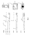
- a prior art nonlinear mapping technique is shown therein. For simplicity, only a single scan line is illustrated.
- the top illustration depicts a typical output voltage of a digital-to-analog converter (DAC) in a computerised imaging system 13.
- the middle illustration indicates the lumen values emitted by a typical CRT display driven by system 13 relative to the DAC voltage.
- the bottom figure illustrates human perception of intensity of the same video information represented in the proceeding two illustrations caused by lumen averaging in the human eye optics.
- white 10, black 14 and 50% gray 12 values in the system's palette (as shown by the ordinate).
- the system is attempting to reproduce an original input which is a constant 50% gray.
- the system would select a gray value 16 for each pel of the image.
- the numbers corresponding to image pel values utilised by a typical computer in a digital video image processing system, are operated upon by DAC converters, these values may be thought of as representing voltages directly, which explains the labelling of the ordinate as VOLTS.
- the 50% voltage, corresponding to the gray 12 values 16 are in turn operated upon by a normal nonlinear video monitor, these gray values correspond to 25% lumens.
- physiology of the eye is such that it perceives 25% lumens as being midway between 100% white and 0% black, which is precisely what a camera capturing the original image intended.
- the average voltage out of the DAC converters being acted upon by a video monitor would be the same as in the case of utilising the gray pixel values 16, although in this case alternately pixel values for white 10 and black 14 would have to be selected inasmuch as the gray value is no longer available.
- This oscillation is shown at reference numeral 22 in Fig. 1.
- Fig. 2 again for illustrative purposes, one might imagine a revised mapping program working with numbers representing not voltage but rather lumens in accordance with the invention, which more desirably would provide for image mapping in linear space.
- the original input signal must be converted from volts to lumens, and the palette colours in like manner would be translated to lumens.
- the original input 16 shown in Fig. 1 would thereby be represented in the computer system 13 as a constant 25% lumens shown at reference numeral 24 of Fig. 2, and the colours in the palette would be black, white and 25% lumens gray.
- the gray values 30 would be selected as perfect matches for each pel.
- a midway point 26 for illustrative purposes similar to the midway point 20 of Fig. 1, midway through the conversion one might again assume that the gray level was removed from the palette and if so, again something quite different occurs.
- the video processing system 13 would aim at 25% lumens and not 50% as before, therefore choosing only half as many white pels 28 as it did previously in the case of the example of Fig. 1. Accordingly, the eye would thus perceive the desired 25% lumens as shown at reference numeral 35 and not the jump to the 50% lumens as in the prior example relative to Fig. 1. In other words from the foregoing, it will be apparent that the loss of the gray pel values would not make the image appear twice as bright as it should be.
- mapping might be similar after input and palette conversion.
- a quantisation or granularity problem is associated with linear mapping.
- an original signal would have states spaced nonlinearly when plotted on a linear lumens scale, such as the 16 states shown depicted therein graphically. Although these states are nonlinear, they nevertheless represent equal steps of perception, and thus all states are equally important.
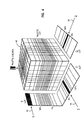
- a preferred embodiment of the present invention invention employs a two-stage lookup as illustrated in Fig. 4.
- each of three 16-bit colour vectors 42-46 are employed to point to its own lookup table to select one of approximately 50 very strategically placed states.
- the results of these three lookups may be combined to form a single pointer into a large three-dimensional lookup table that holds the closest palette colours in the manner of the invention to be here- inafterdescribed in greater detail.
- Lookup tables have been well known and employed in the video image processing field for several years.
- the theoretically minimum table size is the size of the palette which, in the present example, is just 256 entries. With linear diffusion applied in a straightforward manner, as described previously, it is readily apparent that table size becomes impractical.
- the table size may be in the range of 64K to 512K bytes. Adding only ((cube rootoftwo)-1) x 100% more states in each of three colour axes lookup tables results in volume of a three-dimensional lookup table cube, such as cube 48 of Fig. 4, doubling in size. Therefore, the required lookup table size is very sensitive to the efficient placement of colour axes lookup table states, and accordingly optimum placement states are vital to rendering the two-stage lookup method of the invention practical.
- this illustration depicts how the states in the first lookup tables can be optimally positioned in accordance with the present invention.
- the step placements of each of the three colour dimensions may be iteratively refined.
- the "I” row may be conceptually thought of as being slid out of the cube 48 and placed in front of the cube 48 at location 52. Consideration is then made as to what the closest palette colours were. As illustrated in Fig. 5, in the example there may be four closest palette colours 54-60 at the steps on this particular row 52. One of these colours 54 applied to four contiguous steps of "I" in an initial selection of step placement. For this row 52, steps in this range could be rarefied without much accuracy loss. However, one of the colours 56 applied to only a single step in the initial estimate of step placement. Accordingly, for this row 52, accuracy could be gained by concentrating steps in this range.
- the foregoing procedure may be repeated for each "I" row and the number of contiguous steps of the same closest palette across all "I" rows may be averaged, using a reciprocal mean square average.
- states in the colour volume of cube 48 are weighted according to a typical "aim" occurrence during mapping. The resulting average is an indication of how to improve upon the initial step placement estimate. In an area where the average number of contiguous steps is twice as high, only half as many steps are required as were otherwise present for equal accuracy.
- steps may thus be allocated to an area where the average number of contiguous steps is only half as high. Equally important, however, the averages for the three colour axes can be compared whereby steps may be reallocated among the three colours.
- the product of the total states allocated to each of the three colours cannot exceed the size of the large lookup table, but such three values do not need to be powers of two.
- the averages are the same for all steps of all colours.
- the volume covered by the large lookup table extends well beyond saturation in all dimensions to be compatible with high noise diffusion methods. The volume can be considered infinite, but the step allocation algorithm rarefies states beyond saturation so that the memory size of the lookup table is finite.
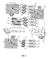
- a flow chart is depicted therein illustrating the sequence of operation of processing in accordance with the present invention.
- the original image has been digitised into a two-dimensional array 70 of picture elements or "pixels", such as pixel 72 each containing a corresponding red, green and blue value 74-78, respectively.
- the red, green, and blue values of each such pixel 72 are combined and used as a pointer into corresponding three lookup tables 78, 80 and 82 translating each pixel into a corresponding linear Y, I and Q value, respectively, 84, 86 and 88, these linearized pixels in combination thereby comprising a linear image 90.
- a process is thereafter provided whereby each pixel in the linear image 90 is in turn processed in an order preferably left-to-right on each row, top row first to bottom row last, for example.
- the colour value of each pixel in the linear image 90 is taken as an "aim" value, wherein the process will attempt to match as closely as possible with the predetermined palette of colours.
- These aim Y, I and Q values 92-96, respectively, are thence each used as a pointer into respective lookup tables 98, 100, 102 in order to translate these aim values 92-96 into a corresponding set of three intermediate numbers obtained from the tables 98-102.
- These three intermediate numbers are then added together as conceptually depicted at reference numeral 104 to yield a pointer 106 to a larger lookup table 108.
- This larger lookup table maps the pointer to a single "mapped" number 110 representing the closest colour in the given preselected palette to the aim colour.
- This mapped number 110 in the mapped image 112 is copied to the pixel of the final mapped image 112.
- this mapped number 110 will reference the predetermined palette to yield a red, green and blue value for display on the image screen.
- Three lookup tables 114-118 translate each of these mapped numbers 110 representing the closest palette colour, back into linear space with mapped Y, I and Q values 120-124.
- This error 128 is then corrected by diffusing an opposite error to adjoining pixels, such error correction being functionally represented at block 130.
- this error 128 may be diffused utilising a positive feedback diffusion kernel in the manner of copending U.S. patent application U.S. serial no. , entitled "Positive Feedback Error
- each pixel 72 is represented by a 16-bit RGB value 74-78.
- the tables 78-82 are preferably precalculated to include the linearity correction and colour vector directions.
- the present invention does not require palette RGB values.
- the linear Y, ),Q values 84-88 which are the aim values for each pel, may each even be translated through its own lookup table into a num- berwhich in the current example is 19 bits.
- the three resulting numbers 99, 101, 103, which are added, may be added in the manner of an article entitled "Pel Colour Encoding with Room for Overflow", IBM Technical Disclosure Bulletin, Vol. 35, No. 1A, June, 1992, p. 52. as shown at adding step 104 resulting in the pointer 106 which will, accordingly, be a 19-bit pointer to the large lookup table 108.
- the closest palette colour is determined and stored in the mapped image 112, as well as being translated back into Y, I, Q values.
- One such alternate mapping method is dither in which a fixed dither pattern is added to an image, then the closest palette colour is found for each of the pixels to which the dither is added. In this method error is not calculated or diffused, rather the variation of the dither pattern is used to evoke a blending of nearest colours in the palette to average to a correct image colour over an area.
- a system of present invention comprises a computer 142, such as an IBM PS/2 personal computer (IBM and PS/2 are trade marks of International Business Machines Corporation) to execute method steps according to the present invention via a program loaded therein implementing the process previously described.
- the computer first captures, by means of an appropriate source, such as a camera 146, scanner or via some other medium, an image based upon a source subject 144.
- the computer 142 then digitises the image for subsequent processing.
- the mapped image created in accordance with the present invention may be stored for display on a conventional monitor 148 for human observation or otherwise stored on media for eventual display.
- a conventional keyboard 143 and other I/O and user-interface devices will further be provided to the computer 142 for initiating the method of the present invention.
- a system bus 152 is provided which ties together the microprocessor 154, the previously described program 156, which instructs the microprocessor 154 how to execute the steps of the invention, and working memory 158, which the microprocessor 154 utilises to store intermediate calculations such as the linear image previously described, the various lookup tables generally represented at reference numeral 160, the original stored image 162 captured by the camera 146 and the mapped image 164 generated from the steps just described.
Landscapes
- Engineering & Computer Science (AREA)
- Multimedia (AREA)
- Signal Processing (AREA)
- Physics & Mathematics (AREA)
- Computer Hardware Design (AREA)
- General Physics & Mathematics (AREA)
- Theoretical Computer Science (AREA)
- Image Processing (AREA)
- Controls And Circuits For Display Device (AREA)
- Processing Or Creating Images (AREA)
- Image Generation (AREA)
Applications Claiming Priority (2)
| Application Number | Priority Date | Filing Date | Title |
|---|---|---|---|
| US92179392A | 1992-07-30 | 1992-07-30 | |
| US921793 | 1992-07-30 |
Publications (2)
| Publication Number | Publication Date |
|---|---|
| EP0581514A2 true EP0581514A2 (fr) | 1994-02-02 |
| EP0581514A3 EP0581514A3 (fr) | 1995-06-14 |
Family
ID=25445985
Family Applications (1)
| Application Number | Title | Priority Date | Filing Date |
|---|---|---|---|
| EP93305724A Withdrawn EP0581514A3 (fr) | 1992-07-30 | 1993-07-21 | Méthode pour cartographie d'images dans un espace linéaire. |
Country Status (4)
| Country | Link |
|---|---|
| US (1) | US5598186A (fr) |
| EP (1) | EP0581514A3 (fr) |
| JP (1) | JPH0696221A (fr) |
| CA (1) | CA2093842A1 (fr) |
Cited By (1)
| Publication number | Priority date | Publication date | Assignee | Title |
|---|---|---|---|---|
| US5734368A (en) * | 1993-08-18 | 1998-03-31 | U.S. Philips Corporation | System and method for rendering a color image |
Families Citing this family (6)
| Publication number | Priority date | Publication date | Assignee | Title |
|---|---|---|---|---|
| US5900861A (en) * | 1995-09-28 | 1999-05-04 | Intel Corporation | Table-driven color conversion using interleaved indices |
| JP3929570B2 (ja) * | 1997-10-27 | 2007-06-13 | 富士フイルム株式会社 | 画像処理装置、画像処理システム、画像処理方法および記憶媒体 |
| US6326977B1 (en) | 1998-11-03 | 2001-12-04 | Sharp Laboratories Of America, Inc. | Rendering of YCBCR images on an RGS display device |
| US20020126328A1 (en) * | 2001-03-09 | 2002-09-12 | Lehmeier Michelle R. | Method and apparatus for matching color image data with a corresponding color in a defined color space |
| CN114449244B (zh) * | 2020-10-31 | 2023-07-18 | 华为技术有限公司 | 一种画质调整方法及装置 |
| US11557266B2 (en) * | 2021-06-07 | 2023-01-17 | Microsoft Technology Licensing, Llc | Adaptive recoloring |
Family Cites Families (31)
| Publication number | Priority date | Publication date | Assignee | Title |
|---|---|---|---|---|
| US4513278A (en) * | 1977-09-26 | 1985-04-23 | Burroughs Corporation | Video Synthesizer for a digital video display system employing a plurality of grayscale levels displayed in discrete steps of luminance |
| US4257071A (en) * | 1979-07-09 | 1981-03-17 | Lamb Reginald T | Apparatus for digitizing optical images |
| JPS57185084A (en) * | 1981-05-08 | 1982-11-15 | Nippon Electric Co | False color image display system |
| US4835532A (en) * | 1982-07-30 | 1989-05-30 | Honeywell Inc. | Nonaliasing real-time spatial transform image processing system |
| US4645459A (en) * | 1982-07-30 | 1987-02-24 | Honeywell Inc. | Computer generated synthesized imagery |
| US4667190A (en) * | 1982-07-30 | 1987-05-19 | Honeywell Inc. | Two axis fast access memory |
| US4777651A (en) * | 1984-06-25 | 1988-10-11 | Tektronix, Inc. | Method of pixel to vector conversion in an automatic picture coding system |
| US4879595A (en) * | 1985-10-22 | 1989-11-07 | Konishiroku Photo Industry Co., Ltd. | Technique for reproducing an image read from a color original |
| US4918633A (en) * | 1985-11-25 | 1990-04-17 | Eastman Kodak Company | Digital image noise reduction method and transmission system |
| US4825388A (en) * | 1986-04-01 | 1989-04-25 | Princeton Gamma Tech., Inc. | Apparatus and method for processing digital images |
| US4899394A (en) * | 1986-05-09 | 1990-02-06 | Prodigy Systems Corporation | Apparatus and method for image compression |
| WO1988005622A1 (fr) * | 1987-01-27 | 1988-07-28 | Konica Corporation | Processeur d'images en couleurs |
| JPS63309077A (ja) * | 1987-06-11 | 1988-12-16 | Seikosha Co Ltd | ビデオプリンタ |
| JP2692081B2 (ja) * | 1987-06-12 | 1997-12-17 | ミノルタ株式会社 | 画像メモリのアドレス制御方式 |
| US5040059A (en) * | 1987-08-03 | 1991-08-13 | Vexcel Corporation | Method and apparatus of image mensuration with selectively visible and invisible reseau grid marks |
| JPH07101915B2 (ja) * | 1987-09-21 | 1995-11-01 | コニカ株式会社 | 画像処理装置 |
| US4941193A (en) * | 1987-10-02 | 1990-07-10 | Iterated Systems, Inc. | Methods and apparatus for image compression by iterated function system |
| US5334992A (en) * | 1987-10-26 | 1994-08-02 | Tektronix, Inc. | Computer display color control and selection system |
| US4896029A (en) * | 1988-04-08 | 1990-01-23 | United Parcel Service Of America, Inc. | Polygonal information encoding article, process and system |
| US4874936A (en) * | 1988-04-08 | 1989-10-17 | United Parcel Service Of America, Inc. | Hexagonal, information encoding article, process and system |
| US4998010A (en) * | 1988-04-08 | 1991-03-05 | United Parcel Service Of America, Inc. | Polygonal information encoding article, process and system |
| US4899293A (en) * | 1988-10-24 | 1990-02-06 | Honeywell Inc. | Method of storage and retrieval of digital map data based upon a tessellated geoid system |
| US5046027A (en) * | 1988-11-08 | 1991-09-03 | Massachusetts General Hospital | Apparatus and method for processing and displaying images in a digital procesor based system |
| US5162925A (en) * | 1988-11-17 | 1992-11-10 | Canon Kabushiki Kaisha | Color image processor capable of performing masking using a reduced number of bits |
| JPH0348575A (ja) * | 1989-07-17 | 1991-03-01 | Matsushita Electric Ind Co Ltd | カラー画像形成装置 |
| US5070413A (en) * | 1989-10-10 | 1991-12-03 | Eastman Kodak Company | Color digital halftoning with vector error diffusion |
| US5047842A (en) * | 1989-11-03 | 1991-09-10 | The Trustees Of Princeton University | Color image display with a limited palette size |
| US5054100A (en) * | 1989-11-16 | 1991-10-01 | Eastman Kodak Company | Pixel interpolator with edge sharpening |
| US5038390A (en) * | 1990-06-05 | 1991-08-06 | Kabushiki Kaisha Toshiba | Method of transform data compression using save-maps |
| US5140432A (en) * | 1990-09-12 | 1992-08-18 | Hewlett-Packard Company | Method and system for printing in one or more color planes with improved control of error diffusion |
| US5196924A (en) * | 1991-07-22 | 1993-03-23 | International Business Machines, Corporation | Look-up table based gamma and inverse gamma correction for high-resolution frame buffers |
-
1993
- 1993-04-13 CA CA002093842A patent/CA2093842A1/fr not_active Abandoned
- 1993-06-22 JP JP5150166A patent/JPH0696221A/ja active Pending
- 1993-07-21 EP EP93305724A patent/EP0581514A3/fr not_active Withdrawn
-
1995
- 1995-03-13 US US08/402,770 patent/US5598186A/en not_active Expired - Lifetime
Cited By (1)
| Publication number | Priority date | Publication date | Assignee | Title |
|---|---|---|---|---|
| US5734368A (en) * | 1993-08-18 | 1998-03-31 | U.S. Philips Corporation | System and method for rendering a color image |
Also Published As
| Publication number | Publication date |
|---|---|
| CA2093842A1 (fr) | 1994-01-31 |
| US5598186A (en) | 1997-01-28 |
| JPH0696221A (ja) | 1994-04-08 |
| EP0581514A3 (fr) | 1995-06-14 |
Similar Documents
| Publication | Publication Date | Title |
|---|---|---|
| US5793885A (en) | Computationally efficient low-artifact system for spatially filtering digital color images | |
| EP0218633B1 (fr) | Procede et dispositif permettant de modifier des images numeriques en couleur | |
| EP0321290B1 (fr) | Texture de cellule en couleur | |
| US5170152A (en) | Luminance balanced encoder | |
| JP4363720B2 (ja) | 色パレットを作成する装置 | |
| EP0184901B1 (fr) | Correction de non-uniformité pour un affichage couleur à tube à rayons cathodiques | |
| JPH09271036A (ja) | カラー画像表示方法及び装置 | |
| WO1997037281A1 (fr) | Systeme et procede de conversion d'un espace chromatique | |
| KR20080002994A (ko) | 3-원색 입력 컬러 신호의 n-원색 구동 신호로의 변환 | |
| KR100438648B1 (ko) | 감마 보정표를 계산하는 효율적인 방법 | |
| US6774953B2 (en) | Method and apparatus for color warping | |
| US5619230A (en) | System and method for real-time image display palette mapping | |
| US5818613A (en) | System and method for color space conversion | |
| US5598186A (en) | System and method for image mapping in linear space | |
| US5995655A (en) | System and method for coding colors and storing compensation factors used in color space conversion | |
| JPH0715692A (ja) | 投射型ディスプレイの画像補正装置 | |
| KR930005812B1 (ko) | 컬러 정보기억 및 처리시스템 | |
| US7405736B2 (en) | Efficient perceptual/physical color space conversion | |
| CA2119087C (fr) | Traitement de correction du gamma dans les signaux video | |
| KR20040107614A (ko) | Mpd에 색재현을 위한 색신호 처리장치 및 그 방법 | |
| US7126614B2 (en) | Digital, hardware based, real-time color space conversion circuitry with color saturation, brightness, contrast and hue controls | |
| US7456845B2 (en) | Efficient perceptual/physical color space conversion | |
| US7126591B2 (en) | Image display device | |
| JPH07131742A (ja) | 投射型ディスプレイの画像補正装置 | |
| JPH06269015A (ja) | 画像補正装置 |
Legal Events
| Date | Code | Title | Description |
|---|---|---|---|
| PUAI | Public reference made under article 153(3) epc to a published international application that has entered the european phase |
Free format text: ORIGINAL CODE: 0009012 |
|
| AK | Designated contracting states |
Kind code of ref document: A2 Designated state(s): DE FR GB |
|
| 17P | Request for examination filed |
Effective date: 19940519 |
|
| PUAL | Search report despatched |
Free format text: ORIGINAL CODE: 0009013 |
|
| AK | Designated contracting states |
Kind code of ref document: A3 Designated state(s): DE FR GB |
|
| STAA | Information on the status of an ep patent application or granted ep patent |
Free format text: STATUS: THE APPLICATION HAS BEEN WITHDRAWN |
|
| 18W | Application withdrawn |
Withdrawal date: 19960528 |